How do you boot a computer from punch cards when the computer has no operating system and no ROM?
To make things worse, this computer requires special metadata called "word marks" that can't be represented on a card.
In this blog post, I describe the interesting hardware and software techniques used in the vintage IBM 1401 computer to load software from a deck of punch cards.
(Among other things, half of each card contains loader code that runs as each card is read.)
I go through some IBM 1401 machine code in detail, which illustrates the strangeness of the 1401's architecture and instruction set
compared to a modern machine.
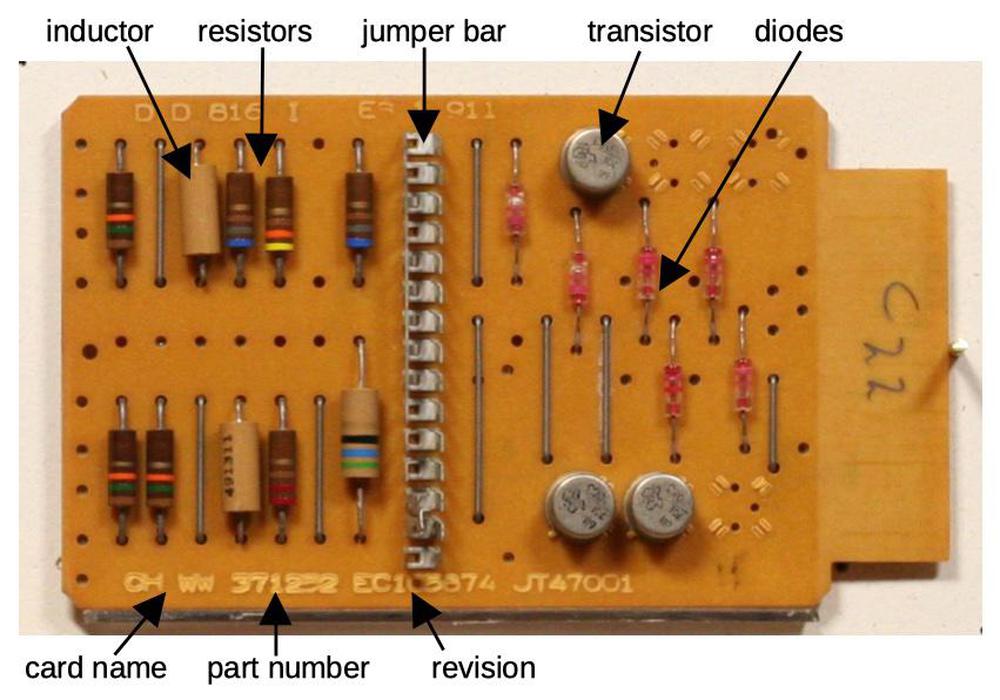
The IBM 1401 was an early all-transistorized computer, so early that it didn't use silicon transistors but germanium transistors.
It was announced in 1959, and went on to become the best-selling computer of the mid-1960s, with more than 10,000 systems in use.
The 1401 leased for $2500 a month (about $20,000 in current dollars), a low price that opened up computing to many companies.
Even a medium-sized business could use the 1401 for payroll, accounting, inventory, order processing, and invoicing.
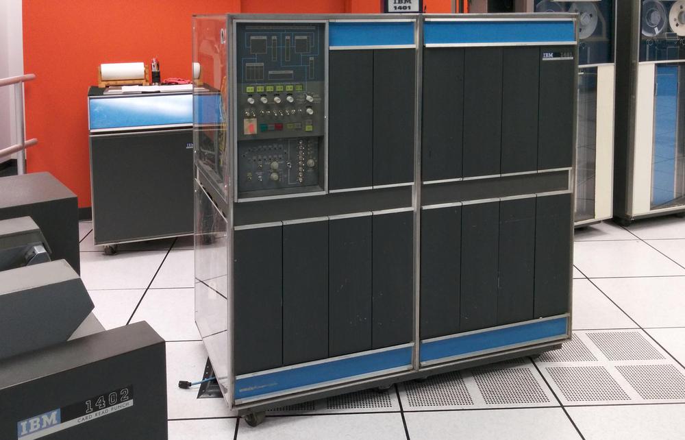
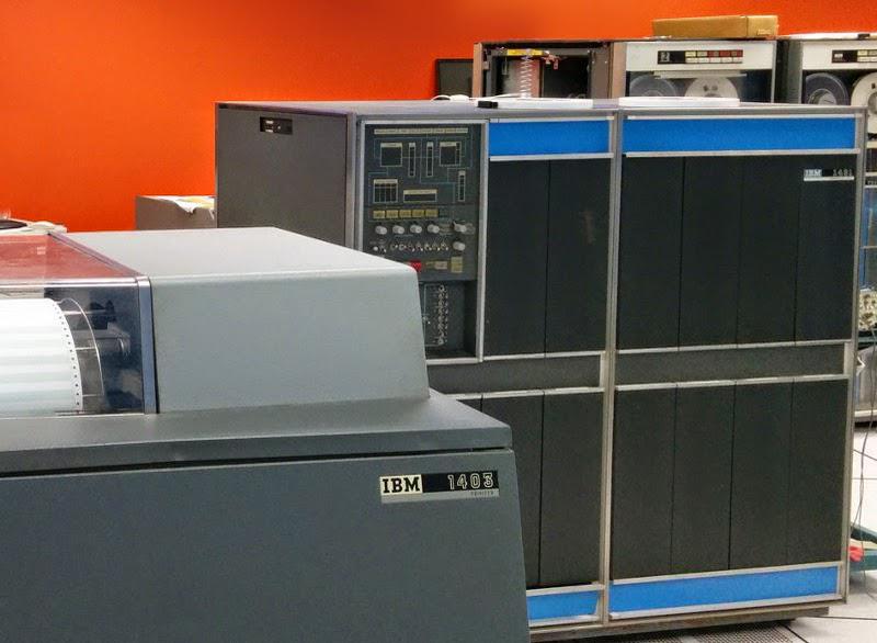
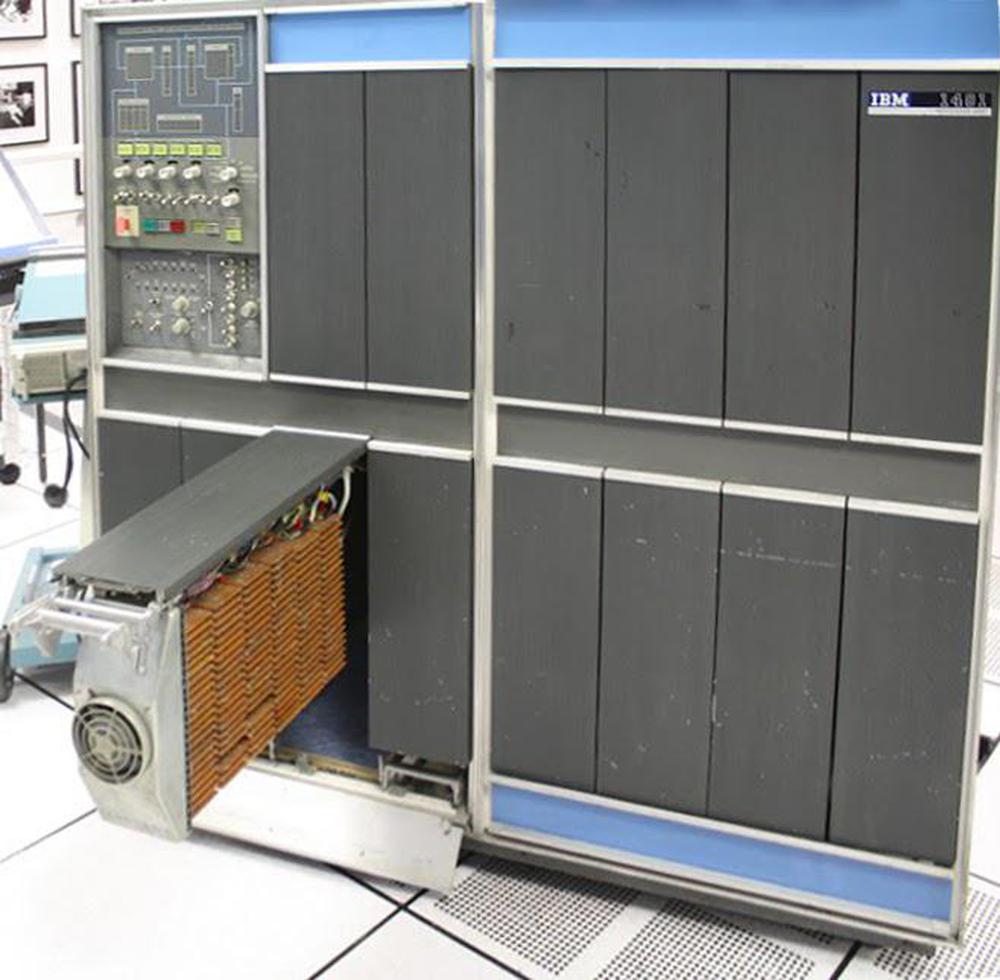
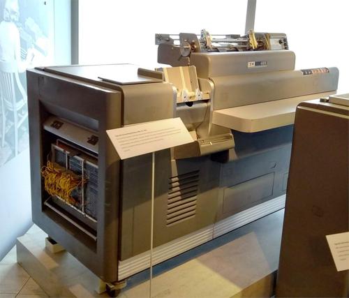
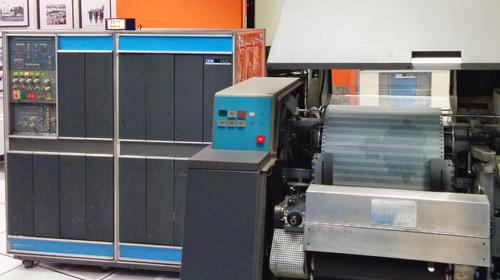
An IBM 1401 mainframe computer at the Computer History Museum. IBM 729 tape drives are at the right.
To understand the 1401's architecture, it helps to understand how punch cards were used in that era.
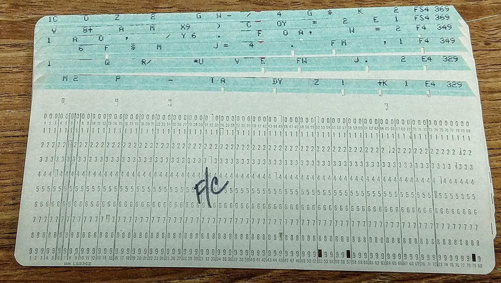
In 1928, IBM developed the 80-column punch card that became the standard for data processing for decades.
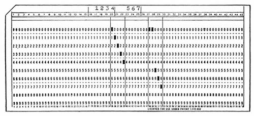
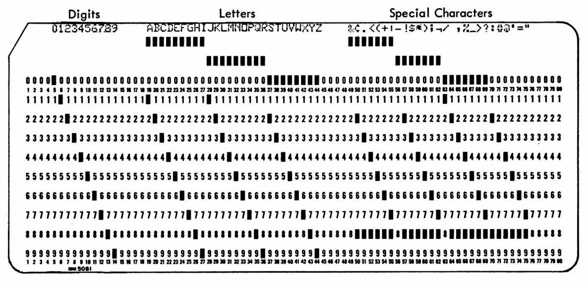
A punch card held 80 characters, one per column, with the character represented by the holes punched in that column, as shown below.
The 6-bit character set was limited to 64 different characters: upper case letters, numbers, and some special characters.
Instead of binary, cards used a BCD-based encoding (which later was extended to create EBCDIC).1
Despite their limitations, punch cards were extensively used for data processing into the 1970s and beyond.
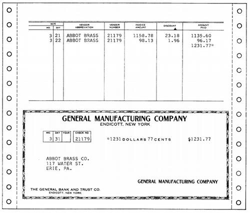
A typical application used one card for each data record, so everything needed to fit into 80 columns2
which were divided up into fixed-length fields.
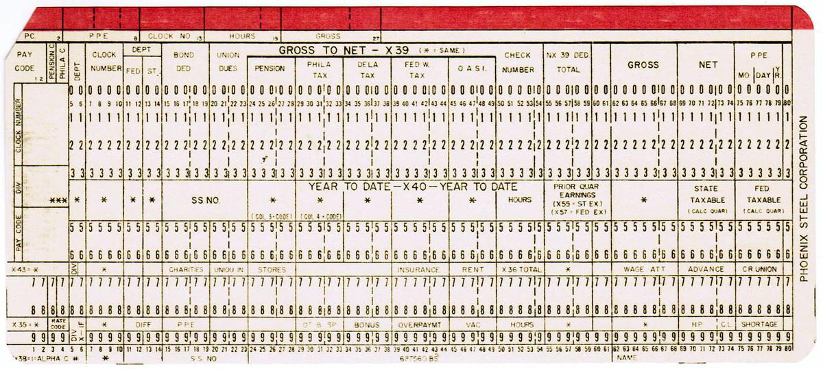
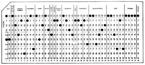
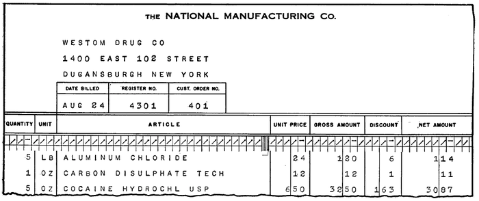
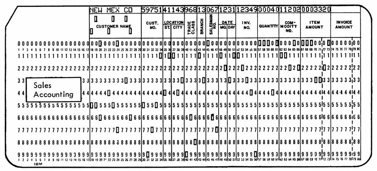
Often, custom cards would be printed that showed the fields for an application, such as the card below designed for accounting.3
Each field has a fixed location. For instance, in the card below, the customer name is from columns 18 to 29 while the invoice amount is in columns 74 through 80.
The IBM 1401 has a peculiar architecture, optimized to support these punch-card applications.
The idea is that fixed-length fields were be delimited in memory by word marks, a sort of metadata, and then instructions operated on
these arbitrary-length fields.
This let you move a 19-character name string with a single instruction. Or you could perform arithmetic on a 50-digit numeric field
with a single instruction.
Thus, word marks were convenient for fixed-field data, since you didn't need to loop over each character of the field.
To implement word marks, each memory location had 6 bits to hold a character as well as a separate bit to hold the word mark.
(These were not bytes, as the IBM 1401 predated the popularity of byte-based computers.)
It's important to note that the word marks were independent of the characters.
Word marks were set or cleared using different instructions from the ones that acted on characters.
Once word marks were configured, they remained unchanged as data records were read into memory.
Word marks were also critical for machine instructions since they indicated the length of the instruction.
A machine instruction in the 1401 consisted of one to eight characters.
The first character was the op code, potentially followed by addresses and/or a modifier.
Each instruction needed to have a word mark set on the op code and a word mark on the next character after the instruction (i.e. the op code of the next instruction).
Note that word marks create a problem. The machine instructions of a program are directly represented as characters on a punch card,
but a punch card cannot hold the necessary word marks.
Thus, loading a program into the 1401 raised two problems. First was the standard computer bootstrap problem: if there's no program in the machine, what performs the load?
But there was a second: word marks are a key component of 1401 machine code, but word marks cannot be represented on punch cards.
In the next section, I'll explain in detail how the IBM 1401 solved these problems.
Loading a program
To load a program, a card deck, such as the short one below is placed into the card reader.
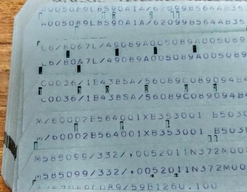
Each card has the contents of the card printed at the top, with the holes punched in the columns below.
The first two cards are bootstrap cards that initialize the computer's memory, clearing it out and setting necessary word marks.
The bulk of the cards hold the machine code of the desired program on the left, and the machine code of the loader on the right.
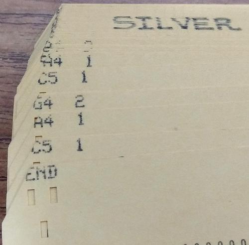
The last card runs the program.
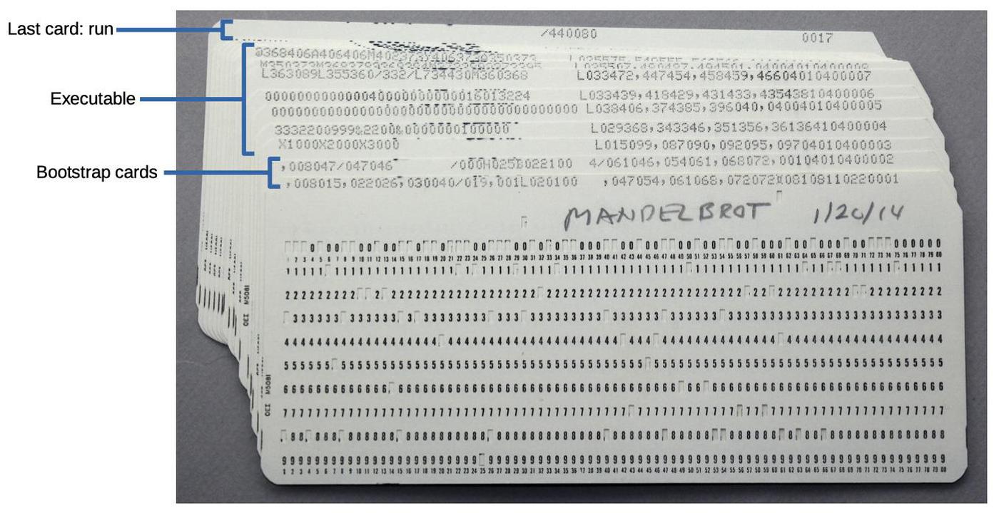
A card deck for my Mandelbrot program.
At the far right of each card, columns 72-75 hold a sequence number (0001 through 0017).
If you dropped a card deck, the cards could be put back into order by a card sorter, sorting on the sequence number.8
The load process was started by pressing the "Load" button on the card reader (the orange button near the center of the blue panel).
This button causes several actions to take place.4
The first card was read, and the contents are placed in memory addresses 1 through 80.
A word mark was set on address 1, and cleared from addresses 2 through 80.
Finally, the instruction at address 1 was executed.
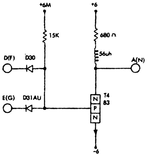
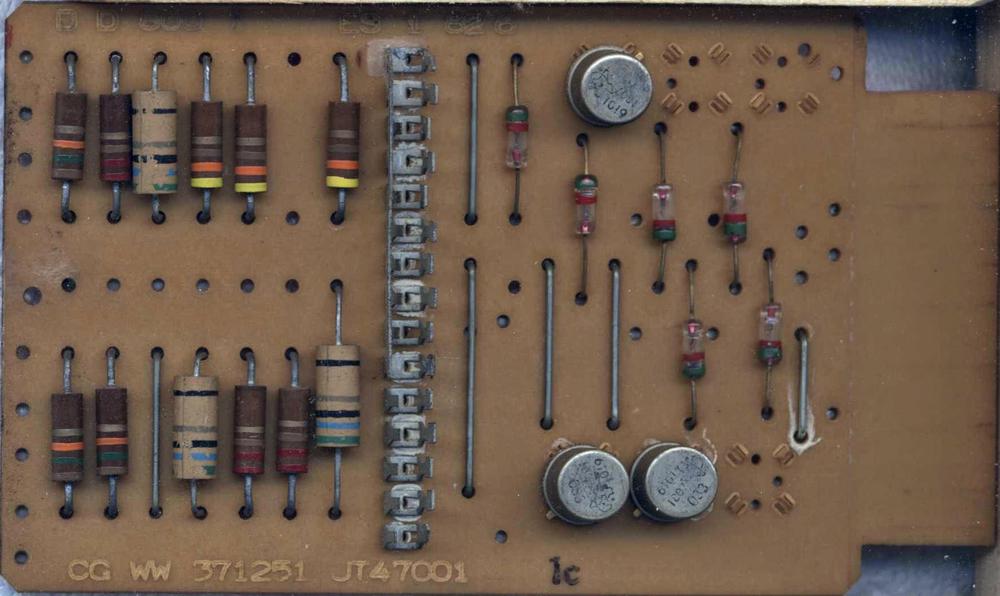
Remember that these operations were implemented in hardware by boards with discrete transistors; there's no microcode or operating system
to help out with these tasks.5
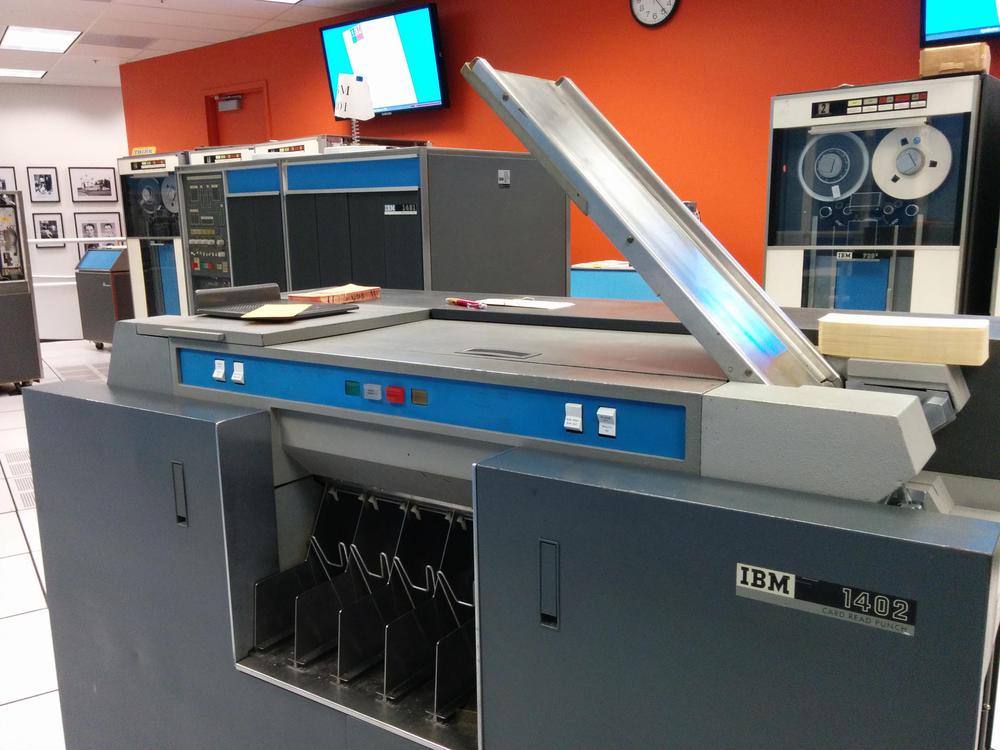
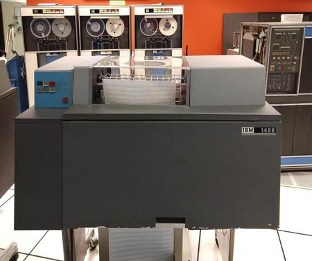
The IBM 1402 card reader/punch. The 1401 computer is in the background (left) and a tape drive is at the right.
Bootstrap card 1
The first card contains the machine code:
,008015,022026,030040/019,001L020100 ,047054,061068,072072⌑08108110220001
The first instruction ,008015 is "Set Word Mark", a critical part of the bootstrap sequence.
The comma is the op code and the address arguments are "008" and "015".
(Since the 1401 is a decimal computer, not binary, the characters "015" are the same as the address 15.)
This instruction sets word marks at the specified addresses, 8 and 15.
Remember that an instruction needs to have a word mark on the opcode and a second word mark on the character following the instruction. The "Load" button put a word
mark at address 1, but what about the second word mark?
It turns out that the hardware has an exception for the "Set Word Mark" instruction 6
allowing it to execute without the second word mark.
(This exception is crucial, since otherwise the first instruction can't execute.
Was this carefully planned or a hack to make things work? I don't know.)
The word marks that were set by the first instruction let the next two instructions run.
They are also "Set Word Mark" instruction, putting word marks at addresses 22, 26, 30, and 40.
Note that each "Set Word Mark" instruction sets two word marks but only "uses up" one, so the code is making progress, preparing word marks
for future instructions.
Now we come to /019; with the slash opcode indicating the somewhat curious "Clear Storage" instruction.
This instruction starts clearing storage at the specified address (19) and
proceeds downwards until the address is a multiple of 100.
Thus, in this case it will clear from address 19 down to address 0, erasing both characters and word marks.
(These locations contained the instructions we just executed.)
A location is erased by storing a blank; this may seem like a strange choice, but keep in mind that an empty punch card column is
read as a blank.
The next Set Word Mark instruction, ,001 puts a word mark back at location 1.
At this point, the contents of memory are as shown below. Word marks are indicated by underlined characters,
which is how the IBM documentation indicated word marks.
40/019,001L020100 ,047054,061068,072072⌑08108110220001
The next instruction is L020100 "Load Characters to a Word Mark".
This instruction copies the character at address 20 (i.e. "4") to address 100.
The instruction then continues copying downwards (copying the blanks) until it hits a word mark (which is at address 1).
To summarize, addresses 20 through 1 are copied to addresses 100 through 81. Locations 81 through 99 received blanks, while address 100 received a "4".
This may seem pointless, but the "4" will turn out to be an important indicator shortly.
This instruction also illustrates how word marks allow a long field to be copied with a single instruction.
The next three instructions set word marks at addresses 47, 54, 61, 68, and 72.
(The boot code needs to go to a lot of effort to ensure that
word marks are set up for future instructions.)
The next instruction ⌑081081 has IBM's unusual "lozenge" character as the opcode. This instruction clears the word mark at address 81 (which had been copied from address 1).
The final instruction on the card, 1022, reads the next card (opcode 1 is "Read") and then jumps to address 22.
A lot has taken place to execute one card, but the next card has some remarkably tricky code.
Bootstrap card 2
After reading the second bootstrap card, memory locations 1 through 80 hold the data:
,008047/047046 /000H025B022100 4/061046,054061,068072,00104010400002
Execution of this card starts at address 22 with the Clear Storage instruction /000.
Remember how the Clear Storage instruction proceeds downwards until the address is a multiple of 100?
In this case, it will clear address 0 and then immediately stop on address 0 (a multiple of 100).
However, a register called the B register will hold the next address (counting downwards), which will wrap from 0 to the top address in memory.
For simplicity, I'll assume the code is running on a 1401 model with 1,000 characters of memory
so the B register will hold the address 999.7
The next instruction H025 is a tricky bit of self-modifying code. It stores the contents of the B address register into locations 23-25,
changing the "Clear Storage" instruction that we just executed to /999.
Next, the B022100 4 instruction will branch to address 22 if address 100 holds a "4" (which is true because the first card put a "4" there.)
Back at address 22, the Clear Storage instruction was modified to be /999, so it will now clear addresses 999-900.
It is followed by H025, which, as before will store the B register into the Clear Storage instruction. This time it will modify the Clear Storage to start at 899.
Finally, the conditional branch loops back to address 22 as before.
The result is that this loop clears memory 100 characters at a time, using self-modifying code to update the position.
This loop continues until addresses 100-199 are cleared. At this point, the branch instruction will fail because address 100 holds
a blank and not a "4".
At this point, the loop has cleared all of storage from 100 to the end of memory, erasing characters as well as any word marks.
The next instruction is Clear Storage /061046 which clears storage from address 46 down to 0 and then branches to 61.
At address 61, ,001040 sets word marks at addresses 1 and 40.
Finally, 1040 reads the next card and starts execution at address 40.
As with the first card, columns 1 through 80 of the card are read into memory addresses 1 through 80.
The program cards
The next phase consists of reading the desired program into memory. A typical card is:
3332200999&2200&0000000100000 L029368,343346,351356,36136410400004
The left part of the card (columns 1-29) contains machine code for the program that we want to run.
The right part (columns 41-71) contains the loader code that will execute card-by-card, loading that code into the right part of memory and setting word marks.
The first loader instruction L029368 copies the program code from the card reader buffer into the desired memory locations. Specifically, it will copy starting from address 29 down to the word mark at address 1. These characters will be copied into addresses 368 down to 340.
The next instructions set the word marks in this code, at addresses 343, 346, 351, 356, 361, and 364.
This answers the question of how the program in memory gets word marks even though punch cards can't explicitly store word marks.
Finally, 1040 reads the next card and starts executing it at address 40.
The following cards have the same structure: the program on the left and the loader code on the right.
Interestingly, the number of characters of program code is variable because the loader code can set at most 6 word marks per card.
In the worst case, all the characters need word marks so only 6 characters can be provided by the card.
In the best case, 40 characters can fit on the left side of the card.
The run card
The last card has the Clear Storage instruction /333080. This clears memory from address 80 downwards to 0, wiping out the
card buffer and the loader code so the program will start with a clean slate. The Clear Storage instruction then jumps to address 333, starting the execution of the program.
After all this work, the computer finally runs the program we wanted to run.
While the loading process seems very long when written out, the card reader is fast for an electromechanical device, with over 13 cards
per second zipping through it.
The program I used in the example is
a Mandelbrot fractal generator that I wrote.
The photo below shows the results of the program, which took 12 minutes to execute.
I discuss the program in detail in this post.
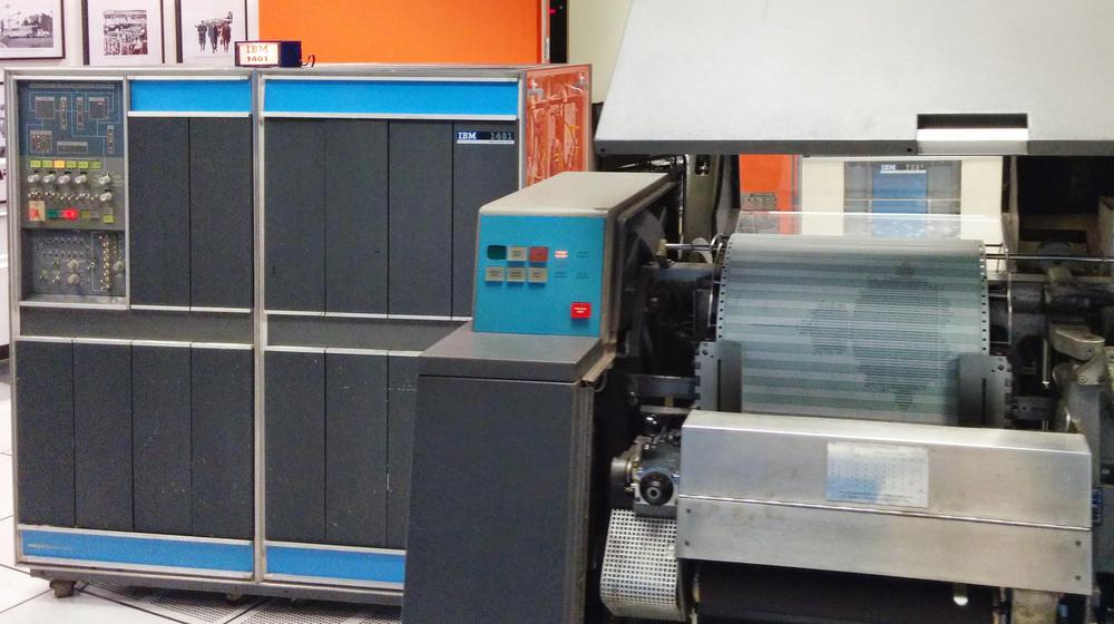
The IBM 1401 mainframe computer (left) at the Computer History Museum printing the Mandelbrot fractal on the 1403 line printer (right).
The bootstrap code I described above is just one of the possible bootstrap sequences.
Programmers could write their own bootstrap code, trying to make it as short as possible.
I described a longer three-card sequence here.
The IBM 1401 could also boot from a magnetic tape using a similar process; pressing the "Tape Load" button on the console loaded a record
from tape, just like booting from a card.
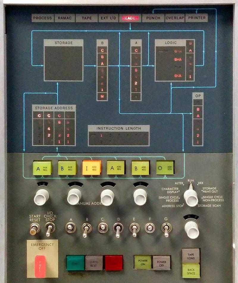
Console of the IBM 1401 computer. The "Tape Load" button is in the lower right.
The origins of "bootstrapping"
The term "bootstrap" has an interesting history.
It starts with physical boots, which often had boot straps on the top, physical straps to help pull the boots on (as shown below).
In the 1800s, the saying "No man can lift himself by his own boot straps" was used as a metaphor for the impossibility of improvement solely through one's own effort.
(Pulling on the straps on your boots superficially seems like it should lift you off the ground, but is of course physically impossible.)
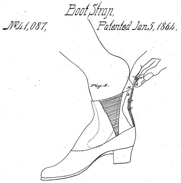
Example of a boot strap at the heel of a boot, from
patent 41087, not the first boot strap patent.
By the mid-1940s, "bootstrap" was used in electronics to describe a circuit that started itself up through positive feedback,
metaphorically pulling itself up by its boot straps.
(See usages from 1943,
1944, and
1946).
By 1952, analog computers used circuits called
"bootstrap integrators".
When a digital computer loaded its program through its own efforts, this took on the name "bootstrap", dating back to the 1950s.
(Using a program to load a program seems as paradoxical as lifting yourself up by your bootstraps, but fortunately it works.)
A 1954 glossary defined "bootstrap" as
"The coded instructions at the beginning of an input tape, together with one or two instructions inserted by switches or buttons into
the computer, used to put a routine into the computer."
A 1955 computer survey published by the Department of Commerce had a similar definition.
Conclusion
Bootstrapping the IBM 1401 was complicated, and the process has become even more complex in later computers.
In the 1960s, computers such as the IBM System/360 had bootstrap microcode stored in read-only storage.
This code could load a chain of bootstrap programs, first a 64-byte bootstrap card, which would then load a 4-kilobyte bootstrap program, which
could then load the disk operating system.
Some early minicomputers and microcomputers lacked ROM and took a step backward, requiring the user to tediously toggle in boot code
through switches on the front panel.
Modern computers go through a much more complex bootstrap process.
The initial boot code for an x86 system is stored in ROM, and booting happens through the BIOS in older computers or UEFI in more modern systems.
The system starts in a primitive state without caches or virtual memory, running a single core in "8086 real mode".
The boot code sets up the system and loads a bootloader program, which may then load another bootloader, which loads the kernel, which
starts up the computer's various processes.
Details are in
this presentation.
Studying the 1401's machine code shows many of its unusual characteristics compared to modern computers and the
strangeness of its instruction set.
Needing to deal with word marks is the most obvious difference, with special instructions to set and erase them.
From a modern perspective, it's unusual to see a computer that doesn't use bytes, although that was common back then.
The use of decimal arithmetic and decimal addressing also seems strange from the modern perspective.
Another curiosity is self-modifying code. Although self-modifying code is discouraged nowadays, it was common on the 1401 (as with other computers of that era).
I announce my latest blog posts on Twitter, so follow me @kenshirriff. I also have an RSS feed.
Notes and references
