Showing posts with label ibm1401. Show all posts

Christmas shopping the IBM way: computerized gift selection in 1962

In 1962, the Simpson's department store in Toronto used an IBM computer to help customers select Christmas gifts, based on the characteristics of the recipients.1 I came across a video that shows how it worked.

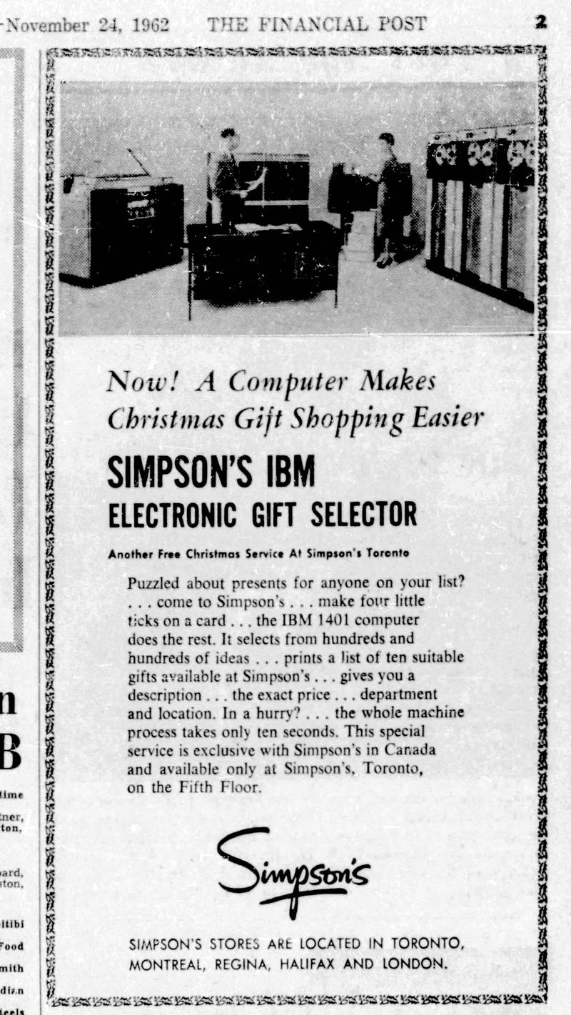
"Now! A computer makes Christmas shopping easier." The IBM 1401 computer is the cabinet at the back, with the 1403 printer to the right of it. The 1402 card reader is at the left and the 729 tape drives at the right, (Click for a larger version.) Advertisement in The Financial Post, November 24, 1962.

"Now! A computer makes Christmas shopping easier." The IBM 1401 computer is the cabinet at the back, with the 1403 printer to the right of it. The 1402 card reader is at the left and the 729 tape drives at the right, (Click for a larger version.) Advertisement in The Financial Post, November 24, 1962.

The IBM 1401 computer (below) was pre-programmed with 3000 categorized gifts.2 A customer described the gift recipient: their age range, their interests, their gender (male, female, or couple), the gift category (e.g. apparel, personal, or "the man who has everything"), and the price range (ranging from $5 to "money is no object").

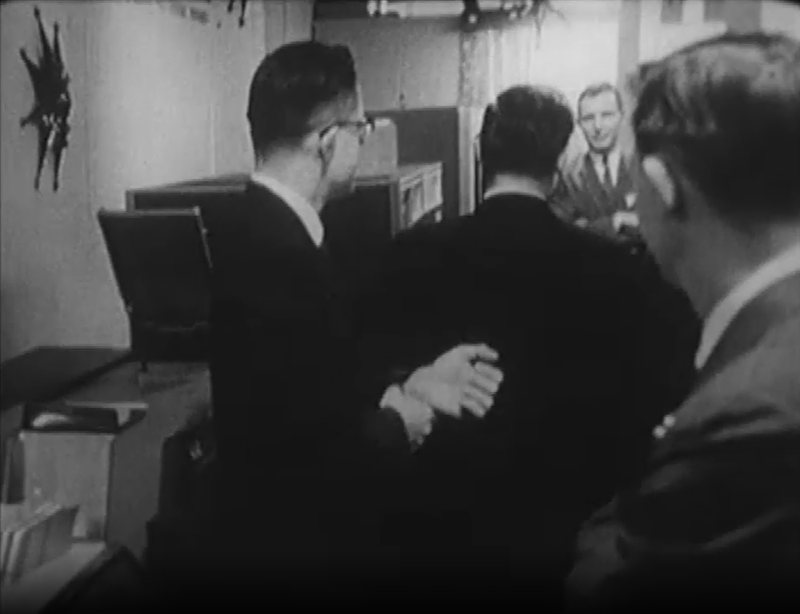
The IBM 1401 computer at Simpson's department store in 1962. The computer is barely visible behind the man's head. The 1402 card reader is at the left. Still from CBC video.

The IBM 1401 computer at Simpson's department store in 1962. The computer is barely visible behind the man's head. The 1402 card reader is at the left. Still from CBC video.

This information was punched onto a card by an operator (called a "girl" in the interview) using an IBM 26 keypunch, as shown below.

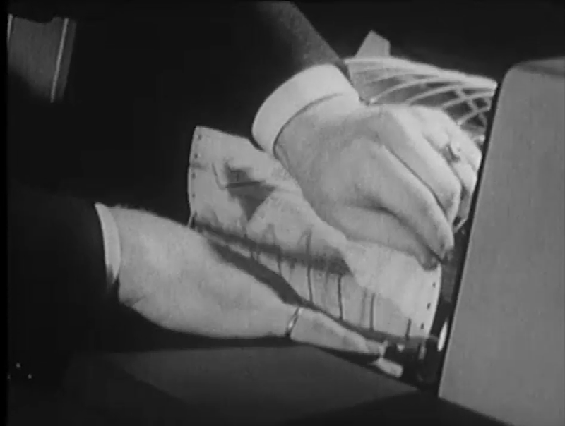
Entering the customer data into the IBM 26 keypunch. Still from CBC video.

Entering the customer data into the IBM 26 keypunch. Still from CBC video.

After running the card through the computer, a gift list with ten suggestions was printed on the IBM 1403 line printer. The list was torn off and given to the customer to help with their shopping.

Removing the Christmas shopping list from the IBM 1403 line printer. The Simpson's logo is barely visible in the upper left corner. Still from CBC video.

Removing the Christmas shopping list from the IBM 1403 line printer. The Simpson's logo is barely visible in the upper left corner. Still from CBC video.

The gift suggestions included a King James bible, Eskimo soapstone, a leather-covered cigarette case, Cossack boots, a Marabou-trim bed jacket, Roto-Shine electric shoe polisher ($26.95), a table lighter in the design of an antique pistol ($4.95), a soda siphon ($15.95) "a little more expensive, probably for your father or your husband", an electrified magnifying glass "to read the stock market report" ($7.95), or moccasins trimmed with seal fur ($6.95). (Gift ideas seem to have changed drastically since the 1960s.)

The interviewer suggested that this computer might take all the fun out of Christmas shopping and called it a "Santa monster", but the operator insisted that most people need some help with their shopping. It must have been an unusual experience for people to encounter a computer in person back then, but this gift computer was very popular, with 2000 people a day using it.

I announce my latest blog posts on Twitter, so follow me @kenshirriff. I also have an RSS feed. Thanks to Tim and Lisa Robinson for tracking down the newspaper clipping.

Notes and references

  1. The video is Christmas Shopping the IBM Way, broadcast on CBC on Dec 18, 1962. The host was Anna Cameron with guest Brian Finney. (Only the first part of the video shows the computer system; most of the video discusses the gift choices in detail.) The system was also discussed in a CBC Radio segment, Christmas Computer Selects the Perfect Gift, reported by Jim McLean and Joelle Pearson on Dec 4, 1962. The radio interview also discusses the use of the system at Gimbel's department store in New York. 

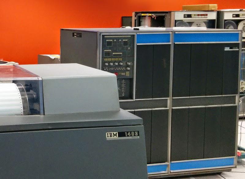
  2. The IBM 1401 computer is just barely visible in the video, so here's a photo that shows an IBM 1401 computer more clearly.

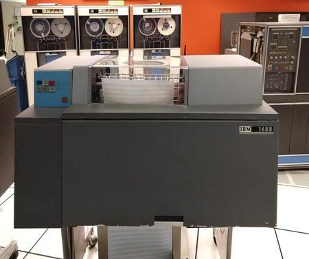
    An IBM 1401 computer. The line printer (1403) is in the foreground, while IBM 729 tape drives are in the background. This computer is at the Computer History Museum.

    An IBM 1401 computer. The line printer (1403) is in the foreground, while IBM 729 tape drives are in the background. This computer is at the Computer History Museum.


Germanium transistors: logic circuits in the IBM 1401 computer

How did computers implement logic gates in the 1950s? Computers were moving into the transistor age, but transistors were expensive so circuits were optimized to minimize the transistor count. At the time, they didn't even use silicon transistors; germanium transistors were used instead. In this blog post, I'll describe one way that logic gates were implemented back then: diode-transistor logic.

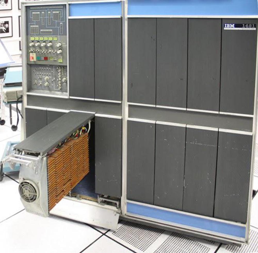
The IBM 1401 computer, showing some of the cards inside. (Click any image for a larger version.)

The IBM 1401 computer, showing some of the cards inside. (Click any image for a larger version.)

The IBM 1401 computer, above, was introduced in 1959 and became the most popular computer of the early 1960s, with more than 10,000 in operation. It was constructed from thousands of circuit cards, each implementing a function such as a few logic gates. The logic gates in the IBM 1401 use (for the most part) a simple form of logic called CTDL (Complemented Transistor Diode Logic) by IBM and DTL (Diode-Transistor Logic) by the rest of the world. As the names suggested, these gates are built from diodes in conjunction with a transistor.1

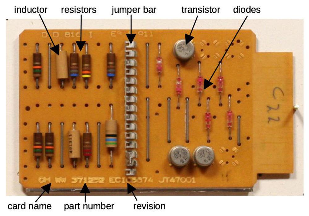
This SMS card (type CHWW) implements three NAND gates so there are three transistors.

This SMS card (type CHWW) implements three NAND gates so there are three transistors.

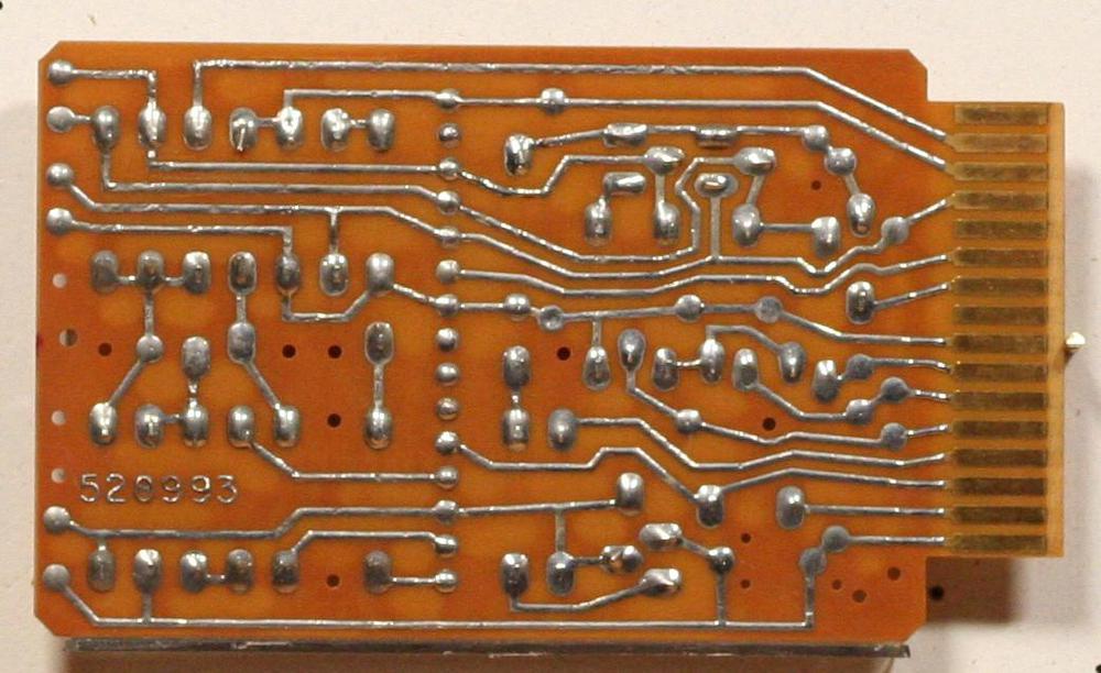
These cards are about the size of a playing card and called SMS cards, Standard Modular System.32 Each type of card has a code, typically four letters. The card above is a "CHWW" card, implementing three NAND gates. It contains a handful of components: transistors, diodes, resistors, and inductors. One unusual component is the jumper bar in the middle, called a "program cap". Breaking off tabs from this bar allowed the functionality of the card to be changed slightly so one card could fill multiple roles. The back of the card (below) shows the traces of the printed circuit board as well as the connector with 16 gold-plated contacts. More details of the CHWW card are in my SMS card database.

The back of the card has the PCB traces and the gold-plated edge connector.

The back of the card has the PCB traces and the gold-plated edge connector.

Logic circuit implementation

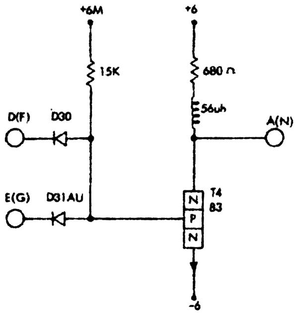
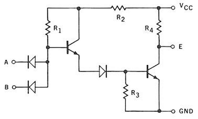
The CHWW card contains three NAND gates. The schematic below, from IBM's 1959 documentation, shows one of these gates. Note IBM's unusual symbol for a transistor, showing the N-P-N structure explicitly, with an external arrow for the emitter.

Schematic of a NAND logic circuit built from a type 83 transistor. From Standard Modular System Component Circuits, p43.

Schematic of a NAND logic circuit built from a type 83 transistor. From Standard Modular System Component Circuits, p43.

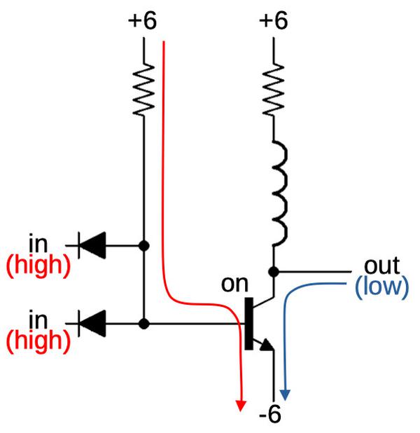
I've redrawn the schematic below using modern symbols. The arrows show (qualitatively) what happens when the gate has two high inputs. The left arrow indicates the current through the resistor and the transistor's base. This base current turns the transistor on, connecting the output to -6 volts, and producing a low output.

If both inputs are high, the output of the gate is low.

If both inputs are high, the output of the gate is low.

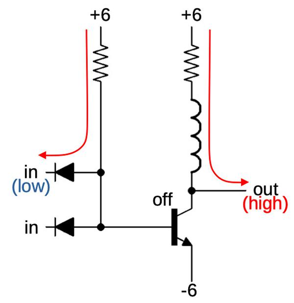
If there are one (or two) low inputs, however, the resistor's current flows out through the diode, rather than through the transistor. With the transistor off, the output is pulled high by the pull-up resistor. The result is a NAND gate: the output is low only if both inputs are high. In this circuit, the diodes are the components that compute the logic function.4 The transistor amplifies (and inverts) the result.5

If an input is low, the output of the gate is high.

If an input is low, the output of the gate is high.

There's a problem with this gate though. The output voltages are approximately +6 volts for a high signal and -6 volts for a low signal. You'd like the gate to switch when an input is roughly in the middle of this range. Unfortunately, the transistor in this circuit will switch when the input is around -6 volts. Thus, the input voltage and output voltage levels are incompatible and you can't connect two gates together.

There are several solutions to this problem. The first solution is to use additional diodes and transistors to shift the voltage levels to be compatible. Fairchild used this approach in their popular Micrologic line of DTL integrated circuits in the 1960s.9 The second solution (used in IBM's SDTDL circuits) is to shift the voltage levels by using additional resistors.

The 1401's gates, instead, uses a surprising solution that avoided extra components. In the gate above, the output voltage levels are raised up compared to the input. But a similar gate with PNP transistors instead of NPN transistors will have the opposite property: the output levels will be lowered. So IBM's solution was to alternate gates built with NPN transistors with gates built with PNP transistors. The first gate raises the voltage level up, and the second gate lowers it back down. You have twice as many types of gates, and it's more complex to design, but you avoid the expense of additional components.

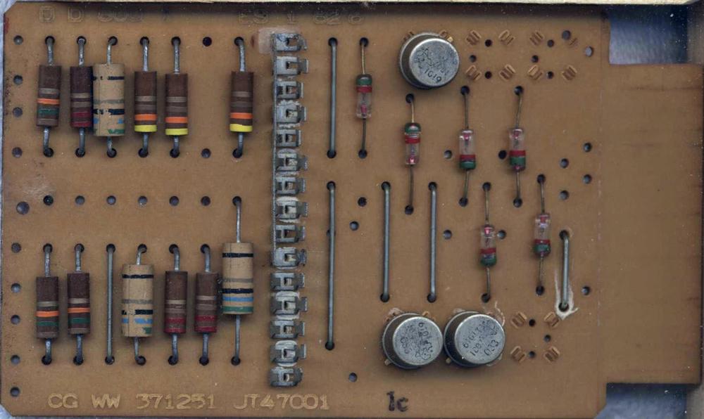
The photo below shows the PNP-based NAND gate card. It is almost identical to the previous NPN card, except the transistors are PNP instead of NPN. The other difference is that it is powered with -12V and 0V instead of -6V and 6V.6

The CGWW NAND card is built with PNP transistors.

The CGWW NAND card is built with PNP transistors.

In more detail, for the NPN gate we first examined, the input switches around -6 volts, and the output is about -6 volts or 6 volts. In the corresponding PNP gate, the input switches around 0 volts, and the output is -12 volts or 0 volts. IBM called the -6V/6V levels type "T" and the 0V/12V levels type "U", so an NPN gate has a U input and a T output, while a PNP gate has a T input and a U output.7 By alternating NPN gates and PNP gates, you have T outputs going to T inputs and U outputs going to U inputs, and everything works.8

The diagram below shows part of the logic diagram from the 1401's adder, heavily simplified. Two type U signals go into the first CHWW gate, which outputs a T signal. The 4JMX gate is a PNP NAND gate that takes T inputs and outputs a U. The CRZV is an NPN buffer that converts U to T. Finally, CNWT is an NPN driver that amplifies a T signal, in this case a binary carry-out signal. Note how the signals alternate between T and U (except for the last special driver).

Simplified excerpt from an IBM ALD logic diagram, page 34.32.16.2.

Simplified excerpt from an IBM ALD logic diagram, page 34.32.16.2.

Wired-OR

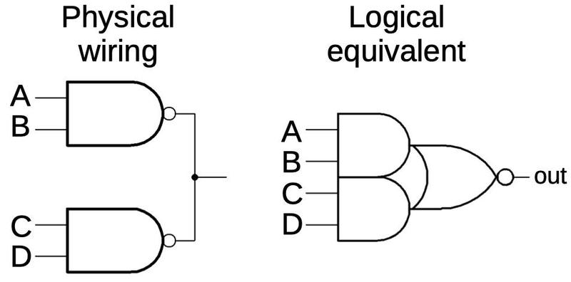
There's one more interesting trick with these logic gates: wired-OR. The idea is that you can wire the outputs of several NAND gates together. If any gate outputs a logical 0, that gate will pull the output low. If all gates output a logical 1, the output will be pulled high by the pull-up resistor. The resulting circuit implements an AND-OR-Invert gate. The diagram below illustrates how the NAND gates are wired together and how the circuit behaves logically. Wired-OR circuits are widely used in the 1401 because you get the OR gate "for free", minimizing circuitry.

An AND-OR-Invert gate. This shows two NAND gates but more can be connected.

An AND-OR-Invert gate. This shows two NAND gates but more can be connected.

There's one minor issue with wired-OR: if you wire standard NAND gates together, you end up with multiple pull-up resistors in parallel, which will affect the gate behavior. The solution is to use gates without pull-up resistors, except for one gate that has the pull-up resistor. For example, the 4JMX card has the pull-up resistor (called a "collector load"), while the 3JMX card lacks it. Thus, a wired-OR could use one 4JMX card and the rest would be 3JMX. (This is one reason why there are so many different types of SMS cards.)

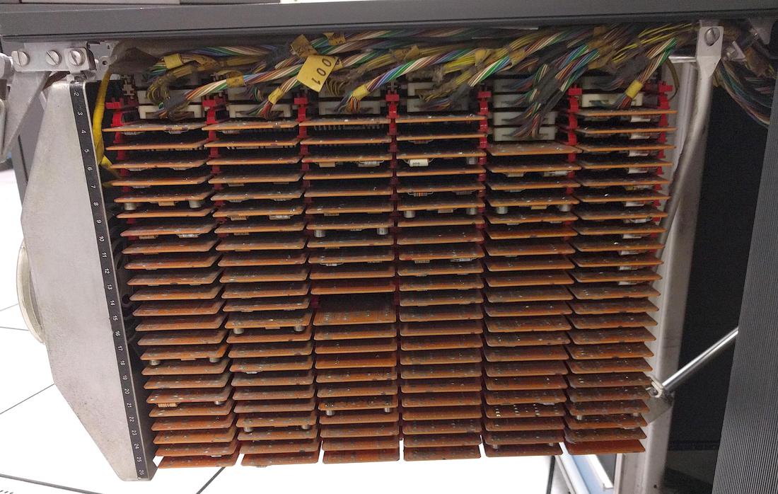
Since each card only implements a small amount of logic, the IBM 1401 computer requires thousands of cards. The photo below shows how they are mounted inside the computer. I won't go into more detail here about how SMS cards are combined to create functional units, but I've written about the circuitry in the 1401's adder if you want to learn more.

SMS cards installed in the IBM 1401 computer. The fan at the left keeps the cards cool.

SMS cards installed in the IBM 1401 computer. The fan at the left keeps the cards cool.

The transistors

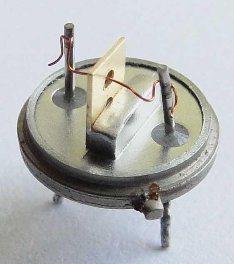
These gates use bipolar NPN and PNP transistors, types of transistors that are still used today. But the germanium alloy-junction transistors were completely different from modern silicon planar transistors. The photo below shows the construction of an NPN alloy transistor, It consists of a P-type germanium crystal base with tin/antimony beads fused on either side to form the emitter and collector. The regions of germanium-antimony alloy form the "N" regions. The resulting N-P-N layers form the NPN transistor. (A PNP transistor is formed similarly, using indium for the alloy.)10 In the photo, the vertical metal plate is the base contact with the tiny germanium disk in the circular hole. Copper wires are connected to the indium beads on either side of the germanium disk.

Inside a germanium alloy-junction transistor used in the IBM 1401 computer. This is an IBM type 083
NPN transistor. Photo from
  IBM 1401 restoration team

Inside a germanium alloy-junction transistor used in the IBM 1401 computer. This is an IBM type 083 NPN transistor. Photo from IBM 1401 restoration team

The 1950s were a time of rapid change in transistor technology. The transistor was invented at Bell Labs in 1947. General Electric invented the alloy junction transistor (used in the 1401) in 1950. In 1953, the drift transistor was created, faster because of its doping gradient. IBM used drift transistors in the Saturated Drift Transistor Diode Logic (SDTDL) family. The first silicon transistors were introduced in 1954. The wafer-based mesa transistor was invented in 1958, followed by the modern planar transistor in 1959. Thus, transistors were undergoing radical changes in the 1950s and IBM introduced new logic families to take advantage of these new transistor types.

Conclusion

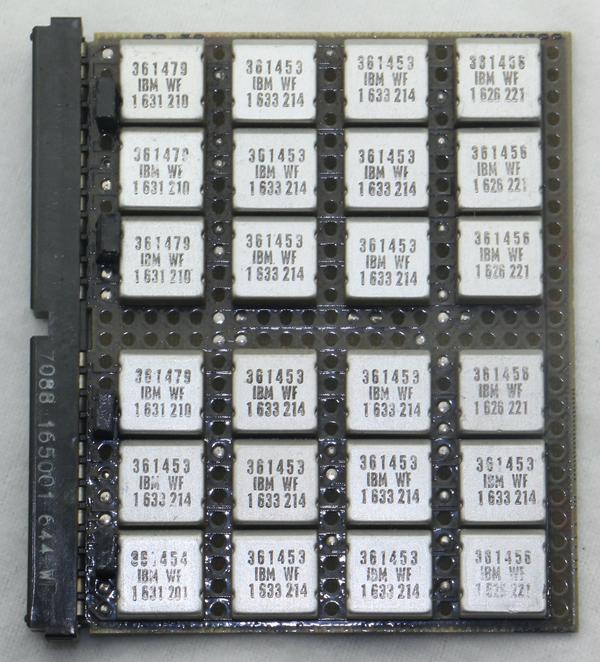
Diode-transistor logic was a key part of IBM's early computers such as the IBM 1401. In 1964, IBM introduced the groundbreaking System/360 line of mainframes. These computers still used diode-transistor logic, but instead of SMS cards with discrete components, the logic was encapsulated in small SLT modules (below) that contained tiny silicon transistors and diodes. An SLT module was roughly equivalent to an SMS card but just half an inch on a side and almost 100 times as reliable. The density, low cost, and reliability of SLT modules were important to the success of the System/360 line.

A board with 24 SLT modules on it, probably from the System/360. The 361453 modules implement AND-OR-Invert.

A board with 24 SLT modules on it, probably from the System/360. The 361453 modules implement AND-OR-Invert.

In the 1960s, diode-transistor logic integrated circuits were introduced. But DTL was soon eclipsed by the rise of TTL (transistor-transistor logic) in the late 1960s. In the 1970s, integrated circuits with MOS transistor logic became common, especially for microprocessors. CMOS logic took over in the 1980s and it's still the most popular logic family. Thanks to Moore's Law, technology has progressed from the IBM 1401 era with a few transistors on a board to modern microprocessors with billions of transistors on a chip.

The Computer History Museum in Mountain View, CA has two working 1401 computers, so stop by for a demo (once the pandemic is over). Thanks to bogomipz for suggesting this topic. Thanks to Randall Neff and Henk Stegeman for SMS card photos. I announce my latest blog posts on Twitter, so follow me @kenshirriff. I also have an RSS feed.

Notes and references

  1. IBM used a dizzying assortment of logic families in that era. Even the 1401 used multiple families (mostly the CTDL discussed above but also current-mode and STDTL in the TAU tape controller, and occasional SDTRL).

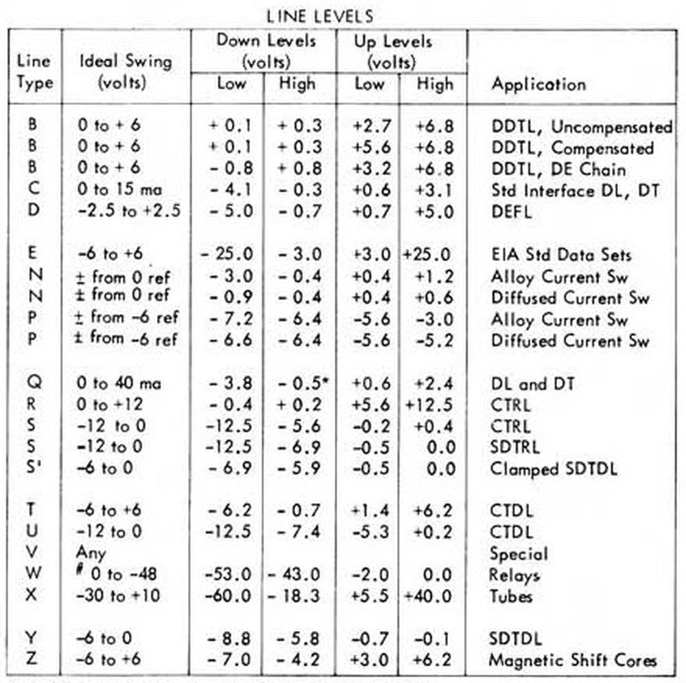
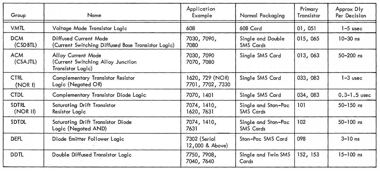
    The table below from 1963 summarizes IBM's numerous logic families. CTRL (Complemented Transistor Resistor Logic) used alloy-junction transistors. It was slow, operating below 200 kilohertz. CTDL (Complemented Transistor Diode Logic) also used alloy-junction transistors but operated up to 250 kilohertz. (The Complemented families alternate NPN and PNP circuits.) Current mode (similar to emitter-coupled logic) was much faster as transistors weren't saturated and the voltage swings were small (±.4V). It operated at 1 megahertz with alloy-junction transistors, and 7 megahertz with diffused junction transistors.

    IBM's logic families from DDTL Component Circuits, 1963, p5.

    IBM's logic families from DDTL Component Circuits, 1963, p5.

    For more discussion, see Transistor Component Circuits and Logic families in the 1401. There's an interesting discussion in Wikipedia's DTL talk page by William Crouse, who designed many of the SDTDL circuits at IBM. 

  2. IBM also offered SMS cards as components for other companies to use in products. The announcement below is from Datamation in 1966.

    A product announcement for SMS cards from Datamation, 1966.

    A product announcement for SMS cards from Datamation, 1966.


  3. The idea behind Standard Module System cards was that IBM could manufacture a small number of standardized cards and build systems from them. Unfortunately, standardization worked better in theory than in practice and IBM ended up with thousands of different card types. As well as logic functions, SMS cards had a wide variety of roles including oscillators, printer drivers, core memory arrays, sense amplifiers, power supply regulation, and tape preamps. 

  4. Many vacuum tube computers used semiconductor diodes as a key part of their logic gates. I think that diodes don't get the recognition they deserve; computer generations are divided into tube versus transistor, without recognizing the gradual introduction of semiconductors in the form of diodes. 

  5. Note the inductor connected to the output of the gate. The inductor increases the speed when pulling the output high. The problem is that the output is pulled high through a resistor, so any capacitance on the output wire results in a delay as it is charged. The inductor counteracts this capacitance. To handwave, once the resistor starts pulling the signal up, the inductor keeps the current flowing. More discussion of the peaking coil here

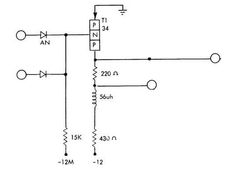
  6. Here's the schematic of the PNP-based NAND gate used in the CGWW card. It is similar to the NPN-based gate, except the circuit is flipped and runs off -12 volts.

    Schematic of a CGWW logic circuit. From Standard Modular System Component Circuits, p42.

    Schematic of a CGWW logic circuit. From Standard Modular System Component Circuits, p42.


  7. IBM used a remarkable number of different voltage levels for its logic families. The CTDL gates described in this article used the "T" and "U" levels. The table below gives the others.

    IBM's logic families used numerous incompatible voltage levels. From the IBM 1401 Pocket Reference.

    IBM's logic families used numerous incompatible voltage levels. From the IBM 1401 Pocket Reference.


  8. I should point out that having two sets of voltage levels makes debugging the 1401 system very confusing. If you measure -3 volts, for instance, this is a logical low for a T signal and a logical high for a U signal. The wired-OR gates also make debugging inconvenient. If the output is low, you can't easily tell which NAND gate is pulling the output low, and these NAND gates may be on different cards with many different inputs. 

  9. The schematic below shows the implementation of a NAND gate in the Fairchild Micrologic family of integrated circuits. This circuit uses an additional transistor and diode to shift the voltage levels. This was practical in an integrated circuit because the additional components had minimal cost. This circuit wouldn't have worked well in the IBM 1401 because the 1401's germanium components provided a much smaller voltage shift than the silicon components in the Fairchild IC.

    Schematic of a Fairchild Micrologic DTL gate from the databook.

    Schematic of a Fairchild Micrologic DTL gate from the databook.


  10. The periodic table shows why elements such as indium were used in the alloy transistors. Note that the semiconductor germanium is in the same column as silicon, which later replaced it. Indium and gallium are in the column to the left, so they have one fewer valence electron. Thus, adding them to the semiconductor makes it more positive (P-type), since electrons are negative. Antimony is to the right; its additional valence electron makes the semiconductor negative (N-type). Tin, in the same column as germanium, was used in the alloy but has no effect on the semiconductor properties.

    This excerpt of the periodic table shows key elements in transistor construction. Source: NCBI.

    This excerpt of the periodic table shows key elements in transistor construction. Source: NCBI.


Booting the IBM 1401: How a 1959 punch-card computer loads a program

How do you boot a computer from punch cards when the computer has no operating system and no ROM? To make things worse, this computer requires special metadata called "word marks" that can't be represented on a card. In this blog post, I describe the interesting hardware and software techniques used in the vintage IBM 1401 computer to load software from a deck of punch cards. (Among other things, half of each card contains loader code that runs as each card is read.) I go through some IBM 1401 machine code in detail, which illustrates the strangeness of the 1401's architecture and instruction set compared to a modern machine.

The IBM 1401 was an early all-transistorized computer, so early that it didn't use silicon transistors but germanium transistors. It was announced in 1959, and went on to become the best-selling computer of the mid-1960s, with more than 10,000 systems in use. The 1401 leased for $2500 a month (about $20,000 in current dollars), a low price that opened up computing to many companies. Even a medium-sized business could use the 1401 for payroll, accounting, inventory, order processing, and invoicing.
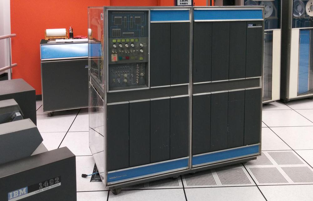
An IBM 1401 mainframe computer at the Computer History Museum. IBM 729 tape drives are at the right.

An IBM 1401 mainframe computer at the Computer History Museum. IBM 729 tape drives are at the right.

To understand the 1401's architecture, it helps to understand how punch cards were used in that era. In 1928, IBM developed the 80-column punch card that became the standard for data processing for decades. A punch card held 80 characters, one per column, with the character represented by the holes punched in that column, as shown below. The 6-bit character set was limited to 64 different characters: upper case letters, numbers, and some special characters. Instead of binary, cards used a BCD-based encoding (which later was extended to create EBCDIC).1
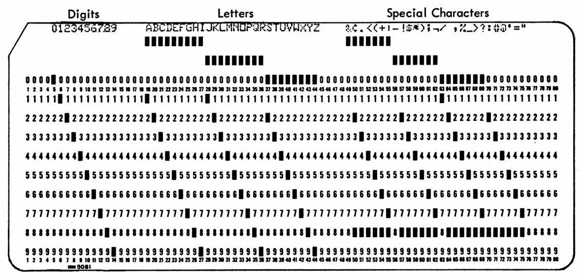
Punch card code, from IBM 29 Card Punch Reference Manual.

Punch card code, from IBM 29 Card Punch Reference Manual.

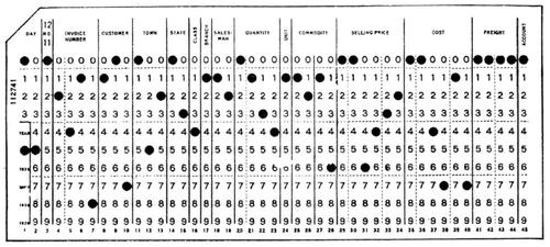
Despite their limitations, punch cards were extensively used for data processing into the 1970s and beyond. A typical application used one card for each data record, so everything needed to fit into 80 columns2 which were divided up into fixed-length fields. Often, custom cards would be printed that showed the fields for an application, such as the card below designed for accounting.3 Each field has a fixed location. For instance, in the card below, the customer name is from columns 18 to 29 while the invoice amount is in columns 74 through 80.
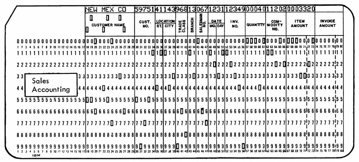
Example card, from IBM 29 Card Punch Reference Manual.

The IBM 1401 has a peculiar architecture, optimized to support these punch-card applications. The idea is that fixed-length fields were be delimited in memory by word marks, a sort of metadata, and then instructions operated on these arbitrary-length fields. This let you move a 19-character name string with a single instruction. Or you could perform arithmetic on a 50-digit numeric field with a single instruction. Thus, word marks were convenient for fixed-field data, since you didn't need to loop over each character of the field.

To implement word marks, each memory location had 6 bits to hold a character as well as a separate bit to hold the word mark. (These were not bytes, as the IBM 1401 predated the popularity of byte-based computers.) It's important to note that the word marks were independent of the characters. Word marks were set or cleared using different instructions from the ones that acted on characters. Once word marks were configured, they remained unchanged as data records were read into memory.

Word marks were also critical for machine instructions since they indicated the length of the instruction. A machine instruction in the 1401 consisted of one to eight characters. The first character was the op code, potentially followed by addresses and/or a modifier. Each instruction needed to have a word mark set on the op code and a word mark on the next character after the instruction (i.e. the op code of the next instruction). Note that word marks create a problem. The machine instructions of a program are directly represented as characters on a punch card, but a punch card cannot hold the necessary word marks.

Thus, loading a program into the 1401 raised two problems. First was the standard computer bootstrap problem: if there's no program in the machine, what performs the load? But there was a second: word marks are a key component of 1401 machine code, but word marks cannot be represented on punch cards. In the next section, I'll explain in detail how the IBM 1401 solved these problems.

Loading a program

To load a program, a card deck, such as the short one below is placed into the card reader. Each card has the contents of the card printed at the top, with the holes punched in the columns below. The first two cards are bootstrap cards that initialize the computer's memory, clearing it out and setting necessary word marks. The bulk of the cards hold the machine code of the desired program on the left, and the machine code of the loader on the right. The last card runs the program.
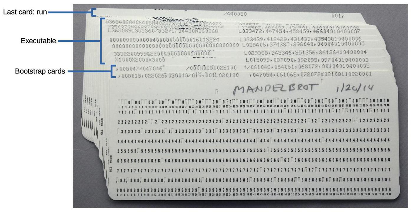
A card deck for my Mandelbrot program.

A card deck for my Mandelbrot program.

At the far right of each card, columns 72-75 hold a sequence number (0001 through 0017). If you dropped a card deck, the cards could be put back into order by a card sorter, sorting on the sequence number.8

The load process was started by pressing the "Load" button on the card reader (the orange button near the center of the blue panel). This button causes several actions to take place.4 The first card was read, and the contents are placed in memory addresses 1 through 80. A word mark was set on address 1, and cleared from addresses 2 through 80. Finally, the instruction at address 1 was executed. Remember that these operations were implemented in hardware by boards with discrete transistors; there's no microcode or operating system to help out with these tasks.5
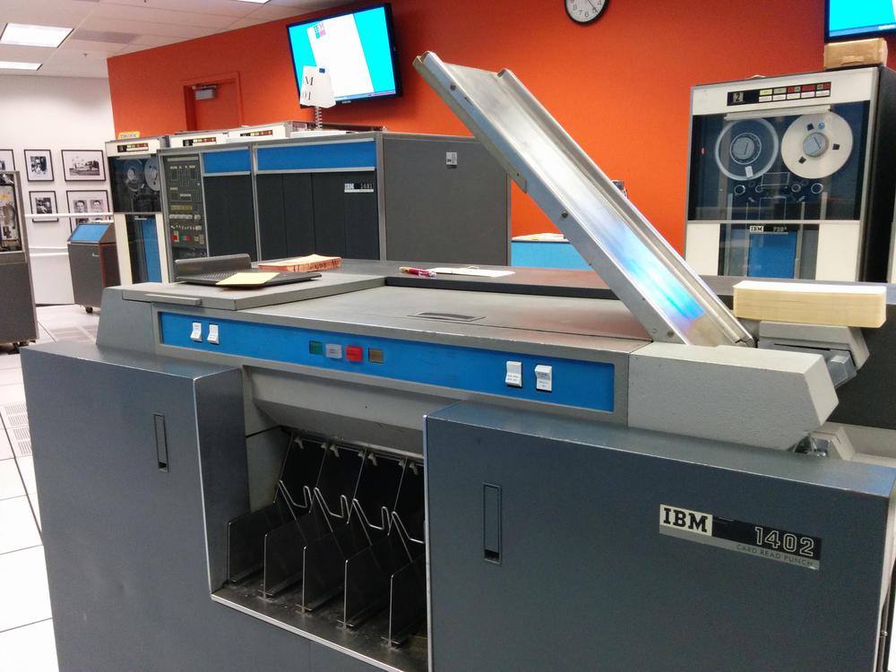
The IBM 1402 card reader/punch. The 1401 computer is in the background (left) and a tape drive is at the right.

The IBM 1402 card reader/punch. The 1401 computer is in the background (left) and a tape drive is at the right.

Bootstrap card 1

The first card contains the machine code:

,008015,022026,030040/019,001L020100   ,047054,061068,072072⌑08108110220001

The first instruction ,008015 is "Set Word Mark", a critical part of the bootstrap sequence. The comma is the op code and the address arguments are "008" and "015". (Since the 1401 is a decimal computer, not binary, the characters "015" are the same as the address 15.) This instruction sets word marks at the specified addresses, 8 and 15.

Remember that an instruction needs to have a word mark on the opcode and a second word mark on the character following the instruction. The "Load" button put a word mark at address 1, but what about the second word mark? It turns out that the hardware has an exception for the "Set Word Mark" instruction 6 allowing it to execute without the second word mark. (This exception is crucial, since otherwise the first instruction can't execute. Was this carefully planned or a hack to make things work? I don't know.)

The word marks that were set by the first instruction let the next two instructions run. They are also "Set Word Mark" instruction, putting word marks at addresses 22, 26, 30, and 40. Note that each "Set Word Mark" instruction sets two word marks but only "uses up" one, so the code is making progress, preparing word marks for future instructions.

Now we come to /019; with the slash opcode indicating the somewhat curious "Clear Storage" instruction. This instruction starts clearing storage at the specified address (19) and proceeds downwards until the address is a multiple of 100. Thus, in this case it will clear from address 19 down to address 0, erasing both characters and word marks. (These locations contained the instructions we just executed.) A location is erased by storing a blank; this may seem like a strange choice, but keep in mind that an empty punch card column is read as a blank. The next Set Word Mark instruction, ,001 puts a word mark back at location 1.

At this point, the contents of memory are as shown below. Word marks are indicated by underlined characters, which is how the IBM documentation indicated word marks.

                   40/019,001L020100   ,047054,061068,072072⌑08108110220001

The next instruction is L020100 "Load Characters to a Word Mark". This instruction copies the character at address 20 (i.e. "4") to address 100. The instruction then continues copying downwards (copying the blanks) until it hits a word mark (which is at address 1). To summarize, addresses 20 through 1 are copied to addresses 100 through 81. Locations 81 through 99 received blanks, while address 100 received a "4". This may seem pointless, but the "4" will turn out to be an important indicator shortly. This instruction also illustrates how word marks allow a long field to be copied with a single instruction.

The next three instructions set word marks at addresses 47, 54, 61, 68, and 72. (The boot code needs to go to a lot of effort to ensure that word marks are set up for future instructions.) The next instruction ⌑081081 has IBM's unusual "lozenge" character as the opcode. This instruction clears the word mark at address 81 (which had been copied from address 1). The final instruction on the card, 1022, reads the next card (opcode 1 is "Read") and then jumps to address 22. A lot has taken place to execute one card, but the next card has some remarkably tricky code.

Bootstrap card 2

After reading the second bootstrap card, memory locations 1 through 80 hold the data:

,008047/047046       /000H025B022100  4/061046,054061,068072,00104010400002

Execution of this card starts at address 22 with the Clear Storage instruction /000. Remember how the Clear Storage instruction proceeds downwards until the address is a multiple of 100? In this case, it will clear address 0 and then immediately stop on address 0 (a multiple of 100). However, a register called the B register will hold the next address (counting downwards), which will wrap from 0 to the top address in memory. For simplicity, I'll assume the code is running on a 1401 model with 1,000 characters of memory so the B register will hold the address 999.7

The next instruction H025 is a tricky bit of self-modifying code. It stores the contents of the B address register into locations 23-25, changing the "Clear Storage" instruction that we just executed to /999. Next, the B022100 4 instruction will branch to address 22 if address 100 holds a "4" (which is true because the first card put a "4" there.)

Back at address 22, the Clear Storage instruction was modified to be /999, so it will now clear addresses 999-900. It is followed by H025, which, as before will store the B register into the Clear Storage instruction. This time it will modify the Clear Storage to start at 899. Finally, the conditional branch loops back to address 22 as before.

The result is that this loop clears memory 100 characters at a time, using self-modifying code to update the position. This loop continues until addresses 100-199 are cleared. At this point, the branch instruction will fail because address 100 holds a blank and not a "4". At this point, the loop has cleared all of storage from 100 to the end of memory, erasing characters as well as any word marks.

The next instruction is Clear Storage /061046 which clears storage from address 46 down to 0 and then branches to 61. At address 61, ,001040 sets word marks at addresses 1 and 40. Finally, 1040 reads the next card and starts execution at address 40. As with the first card, columns 1 through 80 of the card are read into memory addresses 1 through 80.

The program cards

The next phase consists of reading the desired program into memory. A typical card is:

3332200999&2200&0000000100000          L029368,343346,351356,36136410400004

The left part of the card (columns 1-29) contains machine code for the program that we want to run. The right part (columns 41-71) contains the loader code that will execute card-by-card, loading that code into the right part of memory and setting word marks.

The first loader instruction L029368 copies the program code from the card reader buffer into the desired memory locations. Specifically, it will copy starting from address 29 down to the word mark at address 1. These characters will be copied into addresses 368 down to 340. The next instructions set the word marks in this code, at addresses 343, 346, 351, 356, 361, and 364. This answers the question of how the program in memory gets word marks even though punch cards can't explicitly store word marks. Finally, 1040 reads the next card and starts executing it at address 40.

The following cards have the same structure: the program on the left and the loader code on the right. Interestingly, the number of characters of program code is variable because the loader code can set at most 6 word marks per card. In the worst case, all the characters need word marks so only 6 characters can be provided by the card. In the best case, 40 characters can fit on the left side of the card.

The run card

The last card has the Clear Storage instruction /333080. This clears memory from address 80 downwards to 0, wiping out the card buffer and the loader code so the program will start with a clean slate. The Clear Storage instruction then jumps to address 333, starting the execution of the program. After all this work, the computer finally runs the program we wanted to run. While the loading process seems very long when written out, the card reader is fast for an electromechanical device, with over 13 cards per second zipping through it.

The program I used in the example is a Mandelbrot fractal generator that I wrote. The photo below shows the results of the program, which took 12 minutes to execute. I discuss the program in detail in this post.
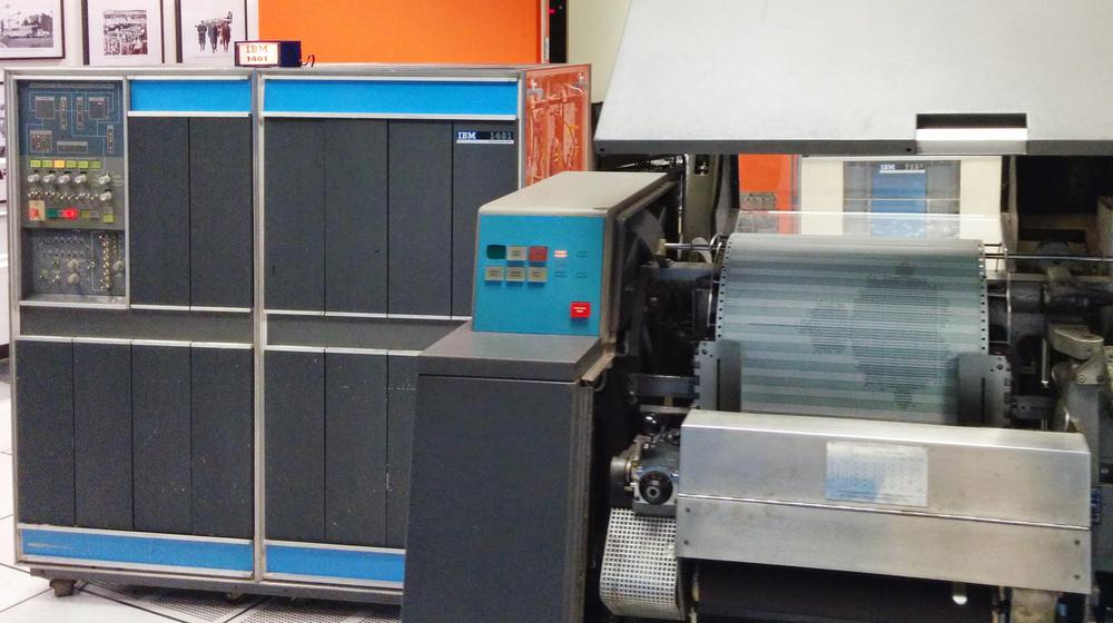
The IBM 1401 mainframe computer (left) at the Computer History Museum printing the Mandelbrot fractal on the 1403 line printer (right).

The IBM 1401 mainframe computer (left) at the Computer History Museum printing the Mandelbrot fractal on the 1403 line printer (right).

The bootstrap code I described above is just one of the possible bootstrap sequences. Programmers could write their own bootstrap code, trying to make it as short as possible. I described a longer three-card sequence here. The IBM 1401 could also boot from a magnetic tape using a similar process; pressing the "Tape Load" button on the console loaded a record from tape, just like booting from a card.
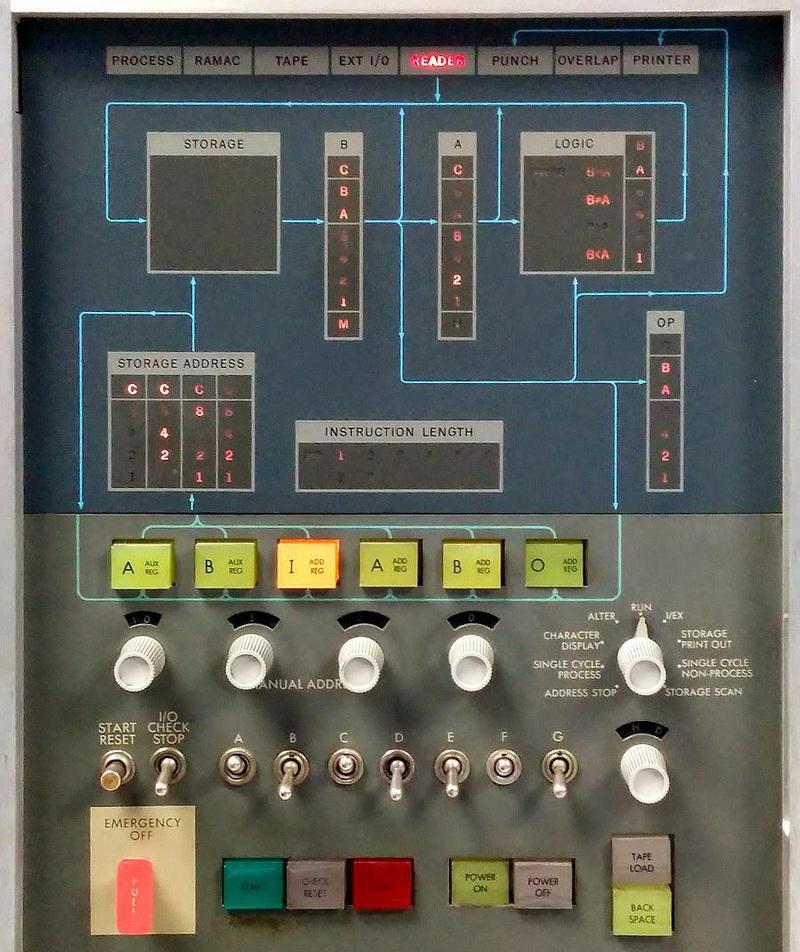
Console of the IBM 1401 computer. The "Tape Load" button is in the lower right.

Console of the IBM 1401 computer. The "Tape Load" button is in the lower right.

The origins of "bootstrapping"

The term "bootstrap" has an interesting history. It starts with physical boots, which often had boot straps on the top, physical straps to help pull the boots on (as shown below). In the 1800s, the saying "No man can lift himself by his own boot straps" was used as a metaphor for the impossibility of improvement solely through one's own effort. (Pulling on the straps on your boots superficially seems like it should lift you off the ground, but is of course physically impossible.)
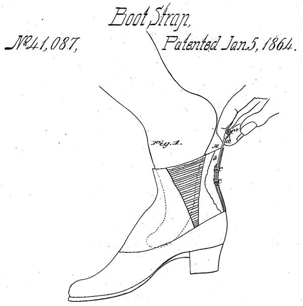
Example of a boot strap at the heel of a boot, from patent 41087, not the first boot strap patent.

Example of a boot strap at the heel of a boot, from patent 41087, not the first boot strap patent.

By the mid-1940s, "bootstrap" was used in electronics to describe a circuit that started itself up through positive feedback, metaphorically pulling itself up by its boot straps. (See usages from 1943, 1944, and 1946). By 1952, analog computers used circuits called "bootstrap integrators".

When a digital computer loaded its program through its own efforts, this took on the name "bootstrap", dating back to the 1950s. (Using a program to load a program seems as paradoxical as lifting yourself up by your bootstraps, but fortunately it works.) A 1954 glossary defined "bootstrap" as "The coded instructions at the beginning of an input tape, together with one or two instructions inserted by switches or buttons into the computer, used to put a routine into the computer." A 1955 computer survey published by the Department of Commerce had a similar definition.

Conclusion

Bootstrapping the IBM 1401 was complicated, and the process has become even more complex in later computers. In the 1960s, computers such as the IBM System/360 had bootstrap microcode stored in read-only storage. This code could load a chain of bootstrap programs, first a 64-byte bootstrap card, which would then load a 4-kilobyte bootstrap program, which could then load the disk operating system. Some early minicomputers and microcomputers lacked ROM and took a step backward, requiring the user to tediously toggle in boot code through switches on the front panel.

Modern computers go through a much more complex bootstrap process. The initial boot code for an x86 system is stored in ROM, and booting happens through the BIOS in older computers or UEFI in more modern systems. The system starts in a primitive state without caches or virtual memory, running a single core in "8086 real mode". The boot code sets up the system and loads a bootloader program, which may then load another bootloader, which loads the kernel, which starts up the computer's various processes. Details are in this presentation.

Studying the 1401's machine code shows many of its unusual characteristics compared to modern computers and the strangeness of its instruction set. Needing to deal with word marks is the most obvious difference, with special instructions to set and erase them. From a modern perspective, it's unusual to see a computer that doesn't use bytes, although that was common back then. The use of decimal arithmetic and decimal addressing also seems strange from the modern perspective. Another curiosity is self-modifying code. Although self-modifying code is discouraged nowadays, it was common on the 1401 (as with other computers of that era).

I announce my latest blog posts on Twitter, so follow me @kenshirriff. I also have an RSS feed.

Notes and references
  1. While punch cards almost always held character data, an optional feature called "column binary" allowed binary data to be punched onto cards, 12 bits in each column. IBM charged $101 a month (in 1960s dollars) for the column binary feature. 

  2. The need to fit all the data into 80 columns was one of the factors that led to the Y2K problem. If you used four columns on a card to hold the year instead of two, you'd need to give up two precious columns somewhere else. 

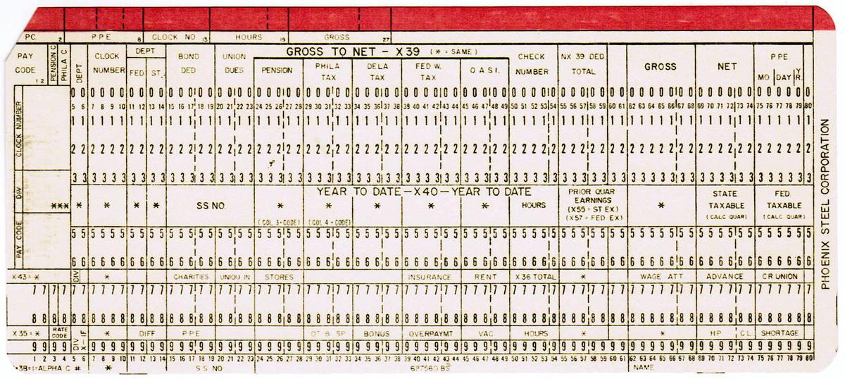
  3. The punch card below is an example of a card custom-printed for a customer application. This card was used for payroll at the Phoenix Steel Corporation.

    A punch card designed for a steel mill.

    A punch card designed for a steel mill.


  4. The operation of the load key is specified in the 1401 reference manual (p118): "This key is used to start loading instruction cards. Pressing the load key operates the read feed until a card has passed the read station. The I -address register is set to 001, and a word mark is set in address 001. All other word marks in addresses 002 through 080 are removed." The instruction in the first columns is executed, and then continued operation is controlled by the first instruction. 

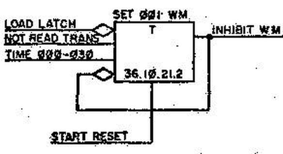
  5. How does the first word mark get set when you load the first card? I looked at the documentation of the circuitry and found the relevant flip-flop (below). It is set by the load button, sets the first word mark (WM), and then is cleared.

    The flip-flop to set word marks. From the 1401 logic diagrams, figure 81.

    The flip-flop to set word marks. From the 1401 logic diagrams, figure 81.

    The photo below shows the card that implements this flip-flop. With the 1401, you can actually see the physical transistors that implement each function.

    A flip-flop card, type "CW".

    A flip-flop card, type "CW".


  6. Instructions need to be indicated with word marks with a few specific exceptions. As documented in the 1401 reference manual (p15) "The 4-character unconditional branch instruction, the 7-character set word mark, and clear storage and branch instructions are the only instructions that can be followed by a blank without a word mark. All other instructions must be followed by a word mark." 

  7. The 1401 computer that I used has 16,000 characters of memory (not 16,384 because it's a decimal machine!) so after the Clear Storage instruction, the B register will hold 15,999, pointing to the top of memory. You might wonder how the address 15,999 is represented in three decimal characters. The trick is that a special address code uses the top two bits of the characters to hold the kilobyte part of the address. The resulting address is 999 with the top two bits of the hundreds and units characters set. The result is the three-character alphanumeric address I9I represents the address 15,999. 

  8. If you had the misfortune to drop your cards, a card sorter could put them back in order using the sequence numbers. A card sorter rapidly sorted cards into slots based on the digit punched in one column. By running the cards through several times, you could sort on the complete sequence number. I discuss card sorters in great detail here. (A low-tech way to keep cards in order was to draw a diagonal line across the top of the cards; it helped when putting cards back in order manually.)

    An IBM Type 83 card sorter. Cards enter the machine on the right, whiz along the top of the machine, and fall into the appropriate hopper underneath.

    An IBM Type 83 card sorter. Cards enter the machine on the right, whiz along the top of the machine, and fall into the appropriate hopper underneath.

    The use of sequence numbers in columns 73-80 goes back to the Fortran language. Fortran was developed for the IBM 704 vacuum tube computer. The 704 was a 36-bit machine. The punch-card reading process used two 36-bit words, so only 72 columns could be read. (These could be any 72 columns of the card, selected by a wiring panel, but typically columns 1-72 were used.) The result was that columns 1-72 were used for code (a restriction still often used), while columns 73-80 were free for sequence numbers. 

Risky line printer music on a vintage IBM mainframe

At the Computer History Museum, we recently obtained card decks for a 50-year-old computer music program. Back then, most computers didn't have sound cards but creative programmers found a way to generate music by using the line printer.2 We were a bit concerned that the program might destroy the printer, but we took the risk of running it on the vintage IBM 1401 mainframe. As you might expect, music from a line printer sounds pretty bad, but the tunes are recognizable and the printer survived unscathed.1

The IBM 1401 business computer was announced in 1959 and went on to become the best-selling computer of the mid-1960s, with more than 10,000 systems in use. A key selling point of the IBM 1401 was its high-speed line printer, the IBM 1403. By rapidly rotating a chain of characters (below), the printer produced output at high speed (10 lines per second) with excellent print quality, said to be the best printing until laser printers were introduced in the 1970s.

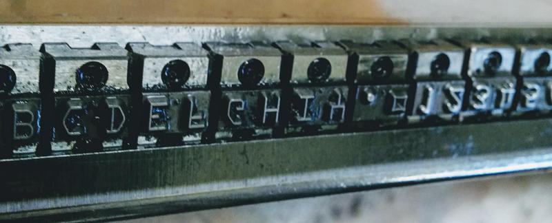
The type chain from the IBM 1401's printer. The chain has 48 different characters, repeated five times.

The type chain from the IBM 1401's printer. The chain has 48 different characters, repeated five times.

Line printers produced a lot of noise, but programmers soon discovered that by printing specific lines of characters, the noise had specific frequencies. It was possible to play a tune by printing the right lines for each note. Around 1970, computer scientist Ron Mak coded up some songs on punch cards using an earlier music program. He recently came across his old programs and gave us the opportunity to try them out.

How the line printer works

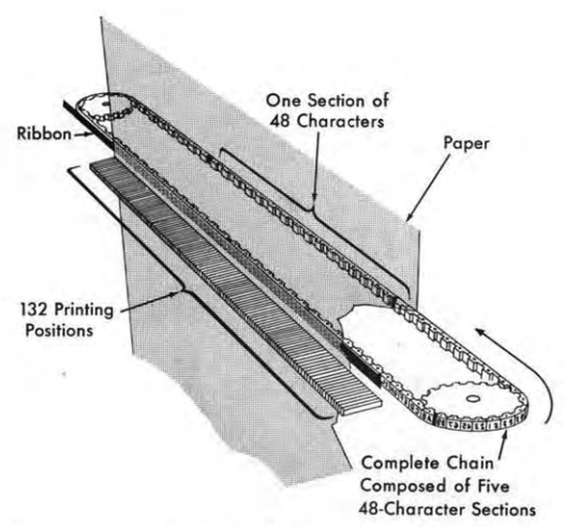
To print characters, the printer uses a chain of type slugs that rotates at high speed in front of the paper, with an inked ribbon between the paper and the chain. The printer produces 132-column output so each of the 132 print columns has a hammer and an electromagnet. At the right moment when the desired character passes the hammer, an electromagnet drives the hammer against the back of the paper, causing the paper and ribbon to hit the type slug, printing the character.

Printing mechanism of the IBM 1401 line printer. From 1401 Reference Manual, p11.

Printing mechanism of the IBM 1401 line printer. From 1401 Reference Manual, p11.

The printer required careful timing to make this process work. The chain spins around rapidly at 7.5 feet per second and every 11.1 µs, a print slug lines up with a hammer. The control circuitry has just enough time to read that position's character from core memory, compare it to the character under the hammer, and fire the hammer if there is a match. After 132 time intervals, each hammer has had an opportunity to print one character; this is called a "scan".3 Since there are 48 characters in the character set (no lower case), this process must be repeated 48 times so all the characters can be printed in any column.54 During each scan, the chain moves by just a single character's width6.

A hammer bank in the IBM 1403 printer. At the bottom, the impact points for the 132 hammers (one for each column) are visible. The coils and wiring for 1/4 (33) of the 132 hammers are visible at the top.

A hammer bank in the IBM 1403 printer. At the bottom, the impact points for the 132 hammers (one for each column) are visible. The coils and wiring for 1/4 (33) of the 132 hammers are visible at the top.

The photo below is a closeup of a hammer. The electromagnet coil and wires are on the upper left. We had to replace this hammer after the coil overheated and smoked; you can see a blackened region on the coil. (This problem happened a while ago due to a bad circuit board, and is unrelated to the printer music.)

An individual hammer from the IBM 1403 printer.

An individual hammer from the IBM 1403 printer.

Generating music

Now that you see how the printer works, with a hammer potentially firing every 11.1 µs, the strategy to make music should be clearer. By printing carefully-selected text, you can control the times at which hammers fire. By firing hammers at specific intervals, you can create a desired frequency. An A note (440 Hz), for instance, can be produced by printing a line of text that fires the hammers every 1/440th of a second. This can be done by printing a 1 in column 1 (the first hammer to be aligned), followed by a # in column 14 on the next scan, a comma in column 30 the scan after that, and so forth. (There's no real pattern to this; it's just how things line up.3) The full line printed to generate this note is below.7 (It may be a bit surprising that with a character set of just 48 characters, the printer includes unusual characters such as ⌑ and ‡.)

1    ⌑Y     C#    0   Q     3,    ‡F      R T   4 -   ,   I     U     $7        M   V .   *        9N     ⌑        ZE     @     P3

The diagram below shows the timing of the hammers, illustrating the uniform 440 Hz frequency produced by the above print line. The diagram has time on the X-axis, with a red bar when each character is printed. The red bars are spaced evenly with a spacing of 1/440th of a second, generating a 440 Hz note. Each bar is labeled with the associated character and column on the page. Note that characters are printed in a different order from how they appear on the line. There's no simple relationship between the arrangement of characters on the line and their time sequence. There are a few gray lines where you'd expect a hammer to fire, but no character is printed. These correspond to times when the chain is syncing up and can't print.

Timing diagram for the note A4. Each red line indicates a printed character.

Timing diagram for the note A4. Each red line indicates a printed character.

By printing a different line, a different note can be produced. Below is the note B5, which is 987 Hz (over an octave higher). As you'd expect, the higher-frequency note has more characters.

1 @EQ4S J   8. N D ‡  S H 7 AM  Y#2   G-  KV . 0 D  Q S J 7&   N D ‡/4  H   AMX0  2 Q G J   W. 0 DP‡  S   7&AM     ‡/4G   *  MX0 D 3

Timing diagram for the note B5. Each red line indicates a printed character.

Timing diagram for the note B5. Each red line indicates a printed character.

The printed line for the low note C♯3 (138 Hz) is below. I was puzzled at first why this line (and the other C♯ notes) had all the characters clustered together, rather than scattered across the line like other notes. It turns out that 138 Hz just happens to correspond to hammers that are consecutive on the line. Even though the characters are clumped together on the line, they are spread out uniformly in time.

16#UZKP*E&38                                                                                                                      

Timing diagram for the note C♯3.

Timing diagram for the note C♯3.

Why chain music might be risky

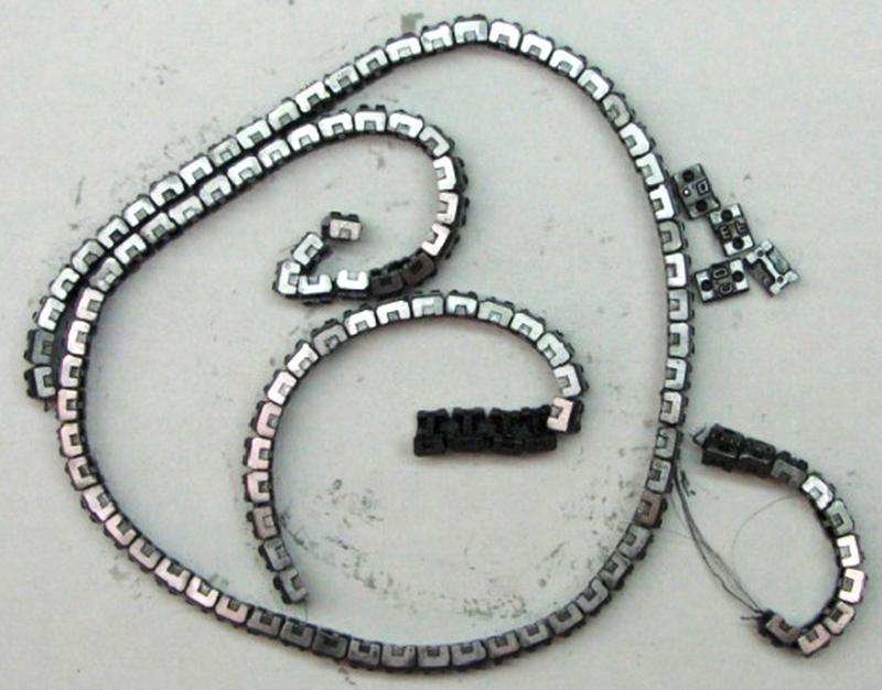
We were concerned that the print chain music program might damage the printer. There are plenty of stories of people destroying line printers by printing a line that fires all the hammers at once. I think these are mostly urban legends (among other things, the hammers on the 1403 fire one at a time, not all at once). Nonetheless, we were somewhat concerned about chain music overstressing the print chain and breaking it. The photo below shows a print chain that broke during normal use; you can see the broken wires and the individual type slugs.

A broken 1403 print chain. It broke during normal use, not from line printer music. (Photo from TechWorks.)

A broken 1403 print chain. It broke during normal use, not from line printer music. (Photo from TechWorks.)

Print chain were manufactured by winding a thin wire into a band, with type blocks attached. Up until recently, print chains were rare and irreplaceable; if the wire broke, there was no way to fix it. However, the Techworks! museum in Binghamton, NY recently developed a technique to rebuild print chains. Because of this, Frank King (our IBM 1401 guru) approved the use of a rebuilt chain for line printer music, with some trepidation. Fortunately, the chain survived the music generation just fine. (After studying the music program carefully, I think it puts less stress on the chain than the average program, unless there's some really unfortunate resonance.)

Closeup of the type chain (upside down) for an IBM 1403 line printer.

Closeup of the type chain (upside down) for an IBM 1403 line printer.

The program

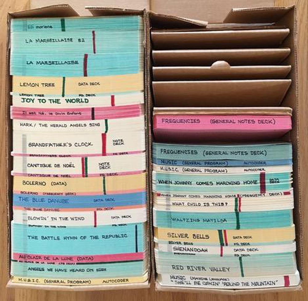
Card decks to play a variety of songs, courtesy of Ron Mak.

Card decks to play a variety of songs, courtesy of Ron Mak.

The source code to the program is long gone, so I disassembled the machine code on the cards to determine how the program works (listing here). First, it reads "frequency cards" that define what line to print for each note. It builds up an array of print lines in memory, along with a table of note names and addresses of the print lines. Next, the program reads the notes of the song, one note per card. (As you can see above, some songs require many cards.) For each note, it looks up the appropriate print line in the note table. Based on the note's duration, it prints the line the appropriate number of times (using a jump table, not a loop). A rest is implemented by looping 200 to 2000 times to provide silence for the appropriate delay.

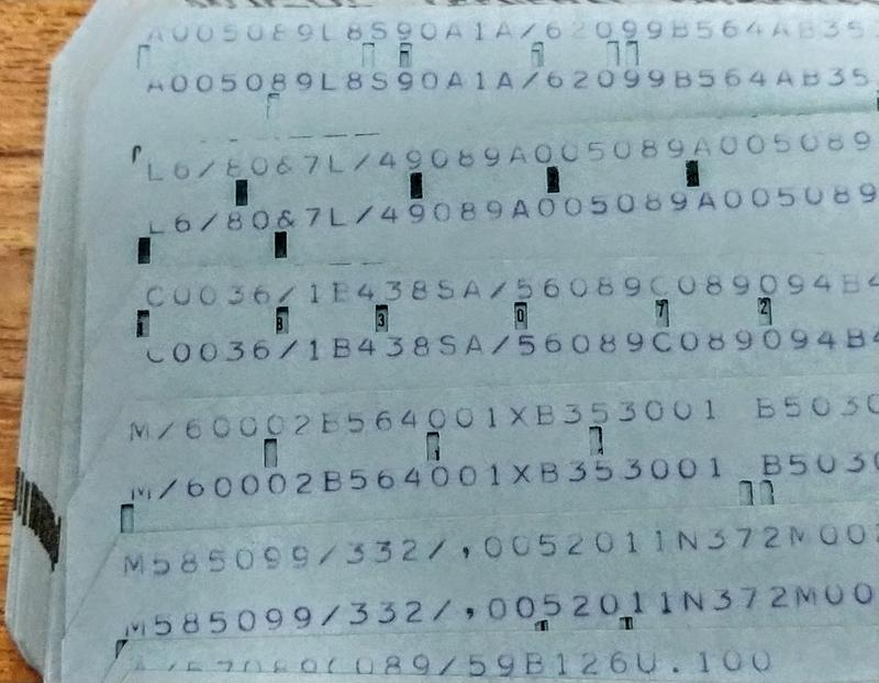
A closeup of cards with the machine code for the music program. For some reason, the contents of each card are printed twice on the card.

A closeup of cards with the machine code for the music program. For some reason, the contents of each card are printed twice on the card.

Machine code for the 1401 is very different from modern machines. One difference is that self-modifying code was very common, while nowadays it is usually frowned upon. For instance, the table of print lines is created by actually modifying load instructions, replacing the address field in the instruction. Even subroutine returns use self-modifying code, putting the return address into a jump instruction at the end of the subroutine. To handle a note, the program generated on-the-fly a sequence of three instructions to load the print line, jump to the print code, and then jump back to the main loop. Self-modifying code made it more challenging for me to understand the program since the disassembled code isn't what actually gets run.

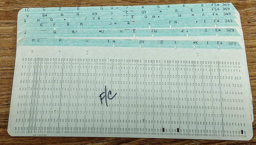
The program cards are followed by frequency cards, defining the print line for each note. The code supported up to 20 different notes, so the frequency cards were selected according to the song's need. Each 132-column line is split across two cards, with the first card defining the right half of the line. Each card is punched at the right with the note name and frequency.

Frequency cards. Each pair of cards defines the 132-character print line that generates the specified note. At the right, the card is punched with the note name (e.g. E4) and frequency (e.g. 329 Hz). The notation F/C labels the first card in the deck.

Frequency cards. Each pair of cards defines the 132-character print line that generates the specified note. At the right, the card is punched with the note name (e.g. E4) and frequency (e.g. 329 Hz). The notation F/C labels the first card in the deck.

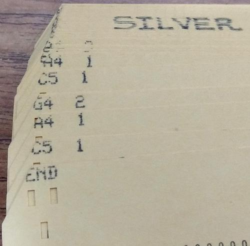
The final set of cards creates the tune, with one card per note (or rest). Each card is punched with a note and duration. A long song may use hundreds of cards. It is straightforward to create a new song, just a matter of punching the tune onto cards. The notes are specified in Standard Pitch Notation with the note name followed by an octave number. For example, C4 is middle C. Since only some print chains had the # symbol, sharps were indicated with an "S", e.g. CS for C♯.

Closeup of the cards for the song Silver Bells. Each card has the note and octave, followed by its duration. The first card is (confusingly) "END", indicating the end of the frequency cards.

Closeup of the cards for the song Silver Bells. Each card has the note and octave, followed by its duration. The first card is (confusingly) "END", indicating the end of the frequency cards.

Conclusion

We succeeded in generating music on the IBM 1403 printer, running programs that hadn't been run in almost 50 years. Although the music quality isn't very good, we were happy that the printer didn't self-destruct. Ron Mak last ran these programs in 1970; this link has some songs from then, such as Raindrops keep fallin' on my head. The video below shows an excerpt of La Marseillaise; in this video you can see each line being printed.

I announce my latest blog posts on Twitter, so follow me at @kenshirriff for future articles. I also have an RSS feed. The Computer History Museum in Mountain View runs demonstrations of the IBM 1401 on Wednesdays and Saturdays so if you're in the area you should definitely check it out (schedule). Thanks to Ron Mak for supplying the vintage programs, Carl Claunch for reading the cards, and the 1401 restoration team for running the program, in particular, Robert Garner and Frank King.

Notes and references
  1. In case you're wondering why nothing shows up on the printer in the video, the printer's line feed was disabled to save paper. You can see the lines being printed in the video at the end of the article. 

  2. Programmers also used the 1401 to generate music on an AM radio via RF interference. Running the right instruction sequence generated a particular tone. We hope to try this in the future. 

  3. I've created an animation of the print chain here that shows exactly how it works; it's more complex than you'd expect. 

  4. The print chain and hammer alignment scheme may seem excessively complicated. But what makes it clever is that the 11.1 µs between hammer times is just enough time to read a character from core memory to see if it matches the chain slug under the hammer, and thus should be printed. In other words, the system is designed to match the mechanical speed of the chain to the electronic speed of core memory. 

  5. The printer's operation is explained in detail in the Field Engineering Manual of Instruction. The section starting on page 37 discusses the chain timing in detail. Each scan is broken down into 3 subscans, but I won't get into that here. Note that while a line is 132 characters, printing a line takes about 150 time intervals (1665 µs); the extra time is used to sync the chain position. (This explains why some notes have "missing" characters in the timing plots.) 

  6. The chain only moves 1/1000 of an inch during the 11.1 µs time., but that is enough to line up the next character and hammer. The trick that makes this work is that the hammer spacing and the chain spacing are very slightly different (a vernier mechanism), so a tiny chain movement causes a much larger change in the alignment position. 

  7. I've archived the code and full set of frequency cards here for future reference. 

Accounting machines, the IBM 1403, and why printers standardized on 132 columns

Have you ever wondered why 132 characters is such a common width for printers? Many printers produced lines of 132 characters, such as the groundbreaking Centronics 101 dot-matrix printer (1970), the ubiquitous DECwriter II terminal (1975), the Epson MX-80 dot-matrix printer (1981), and the Apple Daisy Wheel Printer (1983). Even CRT terminals such as the DEC VT100 (1978) supported 132 columns. But why the popularity of 132 columns?1

After researching this question, I've concluded that there are two answers. The first answer is that there isn't anything special about 132 columns. In particular, early printers used an astoundingly large variety of line widths including 50, 55, 60, 70, 73, 80, 88, 89, 92, 100, 118, 120, 128, 130, 136, 140, 144, 150 and 160 characters.2 This shows there was no strong technical or business reason to use 132 columns. Instead, 132 columns became a de facto standard due to the popularity of the IBM 1401 computer and its high-performance 1403 line printer, which happened to print 132 columns.

The second, more interesting, answer is that a variety of factors in the history of data processing, some dating back a century, led to standardization on several sizes for printed forms. One of these sizes became standard line printer paper holding 132 columns.

The IBM 1401 computer and the 1403 printer

The first printer to use 132 columns appears to be the IBM 1403 line printer, which provided output for the IBM 1401 business computer. The IBM 1401 was the most popular computer of the early 1960s, largely due to its low price. Earlier computers had been limited to large corporations due to their high cost; the IBM 705 business computer rented for $43,000 a month (almost $400,000 in current dollars). But the IBM 1401 could be rented for $2500 per month, opening up the market to medium-sized businesses that used it for payroll, inventory, accounting and many other business tasks. As a result, over 10,000 IBM 1401 computers were in use by the mid-1960s.

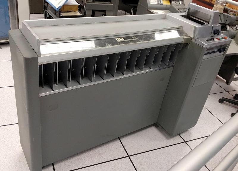
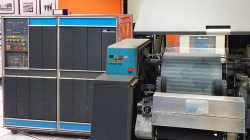
The IBM 1403 printer in front of the popular 1401 business computer (right) and 729 tape drives (left).

The IBM 1403 printer in front of the popular 1401 business computer (right) and 729 tape drives (left).

The IBM 1403 printer was an important part of the 1401's success. This high-speed line printer could print 600 lines per minute of high-quality text, said to be the best print quality until laser printers.10 "Even today, [the 1403 printer] remains the standard of quality for high-speed impact printing," at least according to IBM. By the late 1960s, half of the world's continuous forms were printed on IBM 1403 printers.3

Because the IBM 1403 printer was so popular, its 132-column format became a de facto standard, supported by later printers and terminals for backward compatibility. The 14 7/8"×11" green-bar paper that it used4 remains popular to this day, available at office supply stores.5

Accounting machines / tabulators

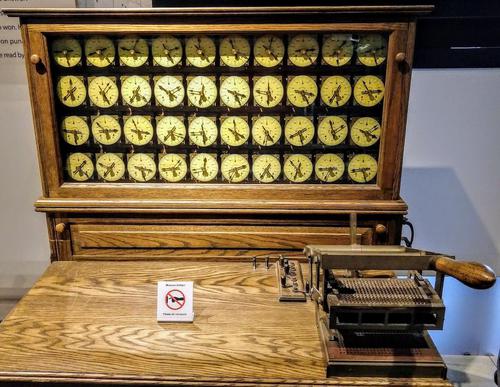
Now I'll discuss the history that led up to 132 columns on 14 7/8" paper. The key actor in this story is the electric accounting machine or tabulator. While these machines are mostly forgotten now, they were the cornerstone of business data processing in the pre-computer era (history). Tabulators date back to the 1890 census when Herman Hollerith invented these machines to tabulate (i.e. count)6 data stored on punch cards. Later tabulators used relays and electromechanical counters to sum up values, were "programmed" for different tasks by a plugboard of wires, and could process 150 punch cards per minute.

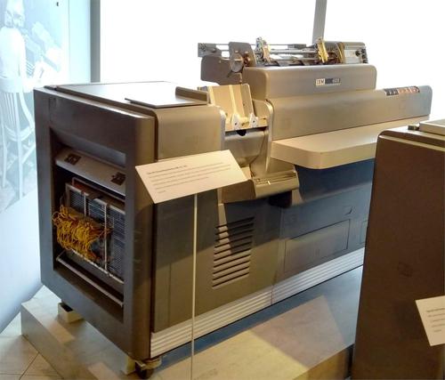
The IBM 403 electric accounting machine. Note the programming plugboard at left with yellow wires. The printer carriage is on top. Cards are fed into the hopper to the left.

The IBM 403 electric accounting machine. Note the programming plugboard at left with yellow wires. The printer carriage is on top. Cards are fed into the hopper to the left.

By 1943, tabulators were popular with businesses and governments; IBM had about 10,000 tabulators in service. These machines were complex, able to handle conditionals while adding or subtracting three levels of subtotals and formatting their alphanumeric output. Accounting machines were used for a wide variety of business data processing tasks such as accounting, inventory, billing, issuing checks, printing shipping labels or even printing W-2 tax forms. While these machines were designed for businesses, tabulators were also pressed into service for scientific computation in the 1930s and 1940s, most famously for nuclear bomb simulations during the Manhattan Project.

IBM 285 accounting machine (1933)

The earliest tabulators displayed the results on mechanical counters so an operator had to write down the results after each subtotal (details). The development of the tabulator printing unit in the 1920s eliminated this inconvenient manual step. One popular printing tabulator was the IBM 285, introduced in 1933. This machine printed values using 3 to 7 "print banks", where each bank consisted of 10 numeric type bars.7 The output below shows 7 column-output, generated by a 285 tabulator with 7 print banks.

Output from the IBM 285 Electric Accounting Machine, showing its 7 columns of counter output. This output is standard typewriter spacing (6 lines per inch), double-spaced. Headings are pre-printed on the form, not printed by the tabulator.

Output from the IBM 285 Electric Accounting Machine, showing its 7 columns of counter output. This output is standard typewriter spacing (6 lines per inch), double-spaced. Headings are pre-printed on the form, not printed by the tabulator.

The character spacing was 5/32" (a value that will be important later), yielding columns 1 7/8" wide. This spacing was about 50% wider than standard typewriter spacing (10 characters per inch) even though the tabulator used standard typewriter line spacing (6 lines per inch). As you can see from the output above, this caused large gaps between the characters. So why did the accounting machine use a character spacing of 5/32"? To understand that, we have to go back a decade.

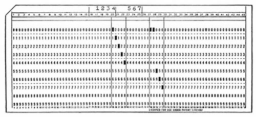
Early IBM punch cards had 45 columns with round holes spaced 5/32" apart.8 The image below shows one of these cards. Each column contained one hole, representing a digit from 0 to 9. One machine used with punch cards was the "interpreter". It read a card and printed the card's contents at the top of the card above the holes. The interpreter used a 45-column print mechanism with type bars spaced 5/32" apart to match the holes.

An IBM 45-column punch card from the early 1920s. This card used round holes, unlike the rectangular holes on "modern" 80-column punch cards. From Electric Tabulating Machines.

An IBM 45-column punch card from the early 1920s. This card used round holes, unlike the rectangular holes on "modern" 80-column punch cards. From Electric Tabulating Machines.

In 1928, IBM introduced the "modern" punch card, which held 80 columns of data (below). These cards used rectangular holes so the holes could be closer together (0.087" spacing). However, IBM kept many of the mechanisms designed for 45-column cards, along with their 5/32" spacing. The result was mismatched products like the IBM 550 Interpreter (1930) that read an 80-column punch card and printed 45 characters at the top of the card. As a result, the characters didn't line up with the holes, as you can see below.9 Likewise, The 285 accounting machine used a type bar printer with 5/32" spacing, even though it used 80-column cards.

The IBM 550 card interpreter read data punched into an 80-column card and printed 45 columns of that data at the top of the card.

The IBM 550 card interpreter read data punched into an 80-column card and printed 45 columns of that data at the top of the card.

IBM 405 (1934) and 402 (1948) accounting machines

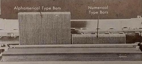
The IBM 285 tabulator could only print digits, but in 1934, IBM introduced the 405, a tabulator that could print alphanumeric information, followed by the improved 402 accounting machine in 1948. Alphanumeric output greatly expanded the uses of the tabulator, as it could print invoices, address labels, employee records, or other forms that required alphanumeric data. The IBM 405 had 88 type bars that moved vertically to print a line of output (below).18 Note the gap for a ribbon guide between the two blocks of type bars.

The IBM 405 accounting machine printed with type bars: 43 alphanumeric ("alphamerical") type bars on the left, and 45 numeric-only type bars on the right. From Electric punched card accounting machines.

The IBM 405 accounting machine printed with type bars: 43 alphanumeric ("alphamerical") type bars on the left, and 45 numeric-only type bars on the right. From Electric punched card accounting machines.

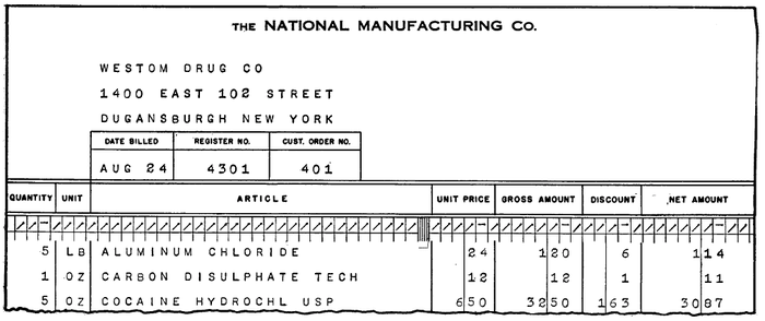
The figure below shows sample output from a 405 tabulator, showing alphanumeric characters on the left side. As with the earlier tabulators, the 5/32" character width resulted in widely separated characters. Note that the headers and boxes were not printed by the tabulator, but were pre-printed on the form.

Output from the IBM 405 tabulator, showing a billing statement. Apparently cocaine was a common product back then. (Electronic Accounting Machines page 17-19.)

Output from the IBM 405 tabulator, showing a billing statement. Apparently cocaine was a common product back then. (Electronic Accounting Machines page 17-19.)

At first forms were hand-fed sheets of paper, but for convenience these were soon replaced by continuous-feed forms.12 To keep forms from slipping out of alignment, holes were added along the sides so forms could be fed by pin-feed or tractor-feed mechanisms. These forms often used a removable 1/2" perforated strip on each side containing the feed holes.22 Thus, the hole-to-hole width was 1/2" less than the overall width, and the printable region was 1" less than the overall width.

Businesses would order customized forms for their particular needs, but these forms were usually produced in standardized widths, given below.11 Surprisingly, these arbitrary-seeming form sizes are still standard sizes available today. Many of the standard form widths are round numbers such as 8" and 11", but there are also strange numbers such as 12 27/32" and 18 15/16".13 I explain most of these sizes in the footnotes.1516 Note that most of the unusual widths are multiples of the 5/32" character width (hole-to-hole); I've highlighted these in yellow. I believe making the width a multiple of 5/32" was a deliberate choice.14

Standard form widths, from the 402 manual, page 151.

Standard form widths, from the 402 manual, page 151.

The 402's 88 character output fit exactly onto a 14 7/8" wide form, while also being a multiple of 5/32" (hole-to-hole).17 I believe that this was the reason that 14 7/8" paper became a standard. This width is the dimension of standard green-bar line printer paper still used today, so this dimension is very important. Note that this paper size became a standard before commercial computers even existed.

IBM 407 accounting machine (1949)

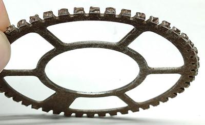
The successor to the IBM 402 accounting machine was the IBM 407 accounting machine, introduced in 1949. The most important feature from our perspective was the move from type bars to type wheels. Each type wheel had 47 characters (letters, numbers and symbols) around the circumference and rotated at high speed to print the correct character.19 The tabulator used 120 of these wheels to print a line of 120 characters.

Type wheel from an IBM 407 accounting machine.

Type wheel from an IBM 407 accounting machine.

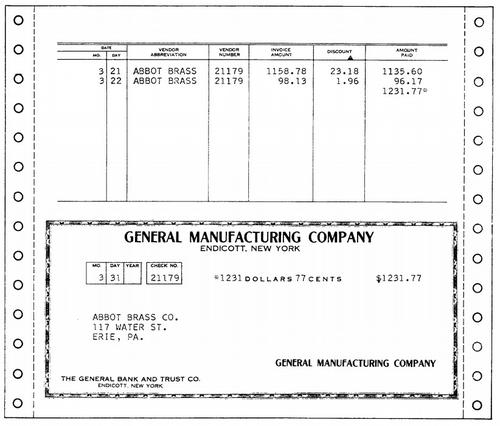
The narrow type wheels enabled the 407 to print 10 characters per inch (standard typewriter pica pitch). The output below shows how the tabulator could issue checks using pre-printed forms. Note that the 407's output looks like normal typing compared to the widely spaced characters of the earlier 405 and 402.

Sample output from an IBM 407 accounting machine. Character spacing is much more natural than the earlier 402 output. Sprocket-fed forms are now common. Figure 128 from Manual of Operation.

Sample output from an IBM 407 accounting machine. Character spacing is much more natural than the earlier 402 output. Sprocket-fed forms are now common. Figure 128 from Manual of Operation.

The 407 operating manual described how to design forms for the 407,20 and listed eleven standard form sizes (below).21 Despite the switch from 5/32" characters to much narrower 0.1" characters, most of the new standard form widths matched the earlier 402 widths (indicated in green). Many of the previous strange form widths (such as 17 25/32") were dropped, but 13 5/8" and 14 7/8" were preserved, which will prove important.

Standard widths for forms for the IBM 407. From 407 Operating Manual page 187.

Standard widths for forms for the IBM 407. From 407 Operating Manual page 187.

The IBM 1403 printer (1959) and its 132 columns

Finally we arrive at the 1403 line printer (1959). This printer supported line widths of 100 character, 120 characters, and 132 characters at 10 characters per inch. The 120 character line is obviously useful for backward compatibility with the 407. But what about 132 characters?

Note that the 13 5/8" form conveniently fit the 407's (or 1403's) 120 character line with a small margin.23 The next-larger standard form width was 14 7/8". The increase of 1.25 inches allows you to add 12.5 characters.24 Thus, the jump from 120 to 132 characters was an obvious product improvement since it makes use of the next standardized form width. One objection is that 130 seems like a more sensible round number—the UNIVAC printer used 130 characters per line—so why not use 130 instead of 132? Due to the complex alignment between the 1403's chain and the print hammers, a line width divisible by 3 (such as 132) works out better.25 I suspect this is the primary reason that the IBM 1403 used 132 characters rather than 130.26 A width of 128 might seem better because of binary, but it's not; the 1401 was a decimal machine so there's no benefit to 128.27

The IBM 1403 printer generating a Mandelbrot set on standard 14 7/8"×11" green-bar paper. The IBM 1401 computer is at the left.

The IBM 1403 printer generating a Mandelbrot set on standard 14 7/8"×11" green-bar paper. The IBM 1401 computer is at the left.

Conclusion

To summarize my hypothesis,28 the 132-character line on 14 7/8" wide paper has its roots in the dimensions of punch cards over a century ago. IBM's early 45-column punch cards resulted in the creation of a printing mechanism with a wide character spacing of 5/32" to match the punch card hole spacing. Even though IBM moved to 80-column cards in 1928, accounting machines continued to use 5/32" characters in the 1930s and 1940s. This resulted in standardized form widths, most importantly 14 7/8" which fit a line of 88 characters. In 1949, IBM's tabulators moved to a standard 10 characters per inch spacing. With that character size and 14 7/8" paper, a 132-character line is natural, and this was implemented on the IBM 1403 printer in 1959.

Because the 1403 printer was wildly popular, 132 character lines on 14 7/8" paper became a de facto standard supported by many other companies. This is why even though punch cards are long obsolete, you can easily buy 14 7/8" green-bar line printer paper to this day.

I announce my latest blog posts on Twitter, so follow me at @kenshirriff for future articles. I also have an RSS feed. I've written about accounting machines before, here and here, if you want to learn more. Thanks to Dag Spicer and Sydney Olson (CHM) and Max Campbell (IBM Archives) for research assistance.

Notes and references
  1. I've been wondering about 132 columns for a long time. I asked the 1401 restoration team about 132 columns a while ago, but didn't get any solid answers. Retrocomputing StackExchange discussed the source of 132 columns last year, but I find the answers unconvincing. 

  2. It's interesting to look at the history of printers and their assorted line widths.

    IBM kept old printing technology around for decades. The print mechanism from the 407 (1949) was reused in the IBM 716 and 717 printers for the IBM 700 series vacuum tube mainframes (1952+) and the IBM 7000 series transistorized mainframes (1958+). The IBM 407 was also used as an output unit for the IBM 650 drum-based computer (1955) and IBM 305 RAMAC disk-based computer (1956). The IBM 1132 printer for the low-end IBM 1130 computer (1965) also used the 407's print mechanism.

    IBM introduced high-speed wire printers (i.e. dot matrix) in 1955, which output 1000 lines per minute; the 719 printer had 60 column output, while the 730 had 120 columns. Unlike modern dot matrix printers, these printers had multiple print heads (30 or 60) for high speed. Unfortunately, these printers were unreliable and a commercial failure. (For details see pages 484-486 of IBM's Early Computers and the Manual of Operation.)

    The RAMAC system (1956) used the IBM 370 printer (unrelated to the later IBM System/370 mainframe), which printed 80 character lines at 10 characters per inch. This printer was very slow; it took about 2 seconds to print a line using a single octagonal typestick (manual).

    In 1970, IBM introduced the IBM System/370 along with the IBM 3211, a new high-speed (2000 lines per minute) line printer. This printer had 132 columns or optionally 150. It was similar to a chain printer except it used a train of character slugs.

    I don't have as much information on non-IBM printers, but in 1954, Remington Rand introduced the first high-speed drum printer, the "High Speed Off Line Printer System" for the UNIVAC computer. This printer produced 600 lines per minute at 130 characters per line. The printer used 18 kW of power and was cooled by 8 gallons per minute of chilled water (details, details). As far as other manufacturers, Analex produced a 120-column line printer. Bull had a printer with 80 print bars and a 92-character alphabetical printer Samsatronic had a 140-character dot matrix printer in the 1950s. Burroughs introduced a fast (1000 line per minute) dot matrix printer (called a wire printer) in 1954 that printed 100 character lines. The Burroughs 220 High-Speed Printer System (1959) used a drum to produce 120 character lines at 1225 lines per minute.

    For an extensive history of printers, see Print Unchained: 50 Years of Digital Printing, 1950-2000 and Beyond. IBM's Early Computers has a detailed discussion of the history and development of IBM printers (Chapter 12.4). It doesn't mention the reason behind different line lengths, unfortunately. For information on printing dimensions of IBM's printers of the 1970s, see Form Design Reference Guide for Printers. More information on early printers can also be found in The U.S. Computer Printer Industry

  3. The estimate that half of the continuous forms volume was printed on IBM 1403 printers is from Print Unchained: 50 Years of Digital Printing, 1950-2000 and Beyond page 102. The estimate is attributed to "one observer" at "some point in the latter 1960s." The IBM 1403 had a long life; IBM 360 and IBM 370 mainframe systems used it into the 1970s. 

  4. As a measure of the popularity of 14 7/8" forms, in 1971 that width was estimated to make up 50% of forms. (Computer Industry Annual, 1971, p309.) 

  5. Although line printers are best known for using 14 7/8" wide paper, the IBM 1403 printer supported forms from 3 1/2" to 18 3/4" wide; see IBM 1403 Printer Component Description pages 11 and 12. Note that the printable region is 13.2", so forms can be much wider than the printable region. 

  6. Confusingly the word "tabulator" was used for two totally different types of machine. Originally, a "tabulator" was a person, "one who tabulates, or draws up a table or scheme" (OED, 1885). The first type of machine using the name "tabulator" was Hollerith's punch-card machine that processed punch cards for the 1890 census, leading to the Hollerith Integrating Tabulator. Note that these tabulators generated output on counter dials (below); they didn't print any output, tabular or otherwise.

    Hollerith Electric Tabulating System (replica). Cards were manually fed into the reader on the right, and results were counted on the dials.

    Hollerith Electric Tabulating System (replica). Cards were manually fed into the reader on the right, and results were counted on the dials.

    The second type of tabulator was the tabulating typewriter (1890). These devices were simply typewriters with tab stops to make it easier to produce tables. (The "tabulating key" on these typewriters is is the root of the "tab" key on the modern computer keyboard.) The decimal tabulator (1896) added multiple tab keys that would tab to the proper location for a 1-digit number, 2-digit number, 3-digit number, etc.

    Underwood 6 typewriter with decimal tabulator (1934). Inset shows the decimal tab keys enlarged: "Tab Stop Clear", ".", "1", "10", "100", "1000", "Tab Stop Set". Interestingly, the platen scale shows 132 tick marks. Photo courtesy of J Makoto Smith.

    Underwood 6 typewriter with decimal tabulator (1934). Inset shows the decimal tab keys enlarged: "Tab Stop Clear", ".", "1", "10", "100", "1000", "Tab Stop Set". Interestingly, the platen scale shows 132 tick marks. Photo courtesy of J Makoto Smith.

    Later IBM punch card tabulators included a printer and printed tabular output, so they were tabulators in both senses. Soon afterward, IBM stopped calling them tabulators and changed the name to Electric Accounting Machine or EAM (1934). 

  7. In the 285 tabulator, the last type bar in a print bank often had an asterisk or "CR" symbol rather than numbers. An asterisk was used to indicate a subtotal, and "CR" indicated a credit (negative number). 

  8. Why did IBM's early punch cards have 45 columns with 5/32" spacing? See The Punched Card for history. The short answer is 28-column cards (from the 1890 census) used 1/8" holes with 1/8" between holes. The gap between holes was halved to 1/16" for 36-column cards, and halved again to 1/32" for 45-column cards, yielding 5/32" spacing. 

  9. IBM's early interpreters printed 45 columns of numeric-only data, on short 34-column cards, 45-column cards, or "modern" 80-column cards (details). (While 45-column cards were originally thought to have almost unlimited capacity to meet all requirements, the increase to 80 columns was soon necessary.) In the 1950s IBM introduced alphabetic interpreters that could print 60 columns of alphanumeric information on a punch card. The IBM 552 interpreter used 60 type bars. The IBM 557 interpreter (1954) switched to 60 typewheels. Apparently, the IBM 557 had reliability problems and later 60-column interpreters went back to type bars: the IBM 548 and IBM 552 (1958 and 1957). 

  10. The high quality of the IBM 1403's print was largely due to the use of a horizontally rotating chain. Earlier printers used type bars, type wheels, or drums. These approaches have the problem that any error in timing or positioning results in characters that are shifted vertically, resulting in objectionably wavy text. On the other hand, positioning errors with a type chain are horizontal, and people are much less sensitive to type that is spaced unevenly. 

  11. Why would customers care about standard form sizes? The 407 reference manual stated that forms of standard sizes can be obtained more quickly and economically from forms manufacturers than non-standard sizes. In addition, when using the pin-feed platen, the platen dimensions had to match to the form width. IBM had standard platens to match the standard form sizes (see 923 parts catalog page 16), but non-standard forms required a custom platen.  

  12. Accounting machines added support for continuous forms in several steps. On early tabulators, the operator needed to stop the machine and manually advance the paper to the top of each form. The IBM 921 Automatic Carriage (1935) provided a motorized mechanism to automatically jump to the top of a form or a particular position on the form. But even with an automatic carriage, the operator needed to ensure the forms didn't slip out of alignment (especially multiple-copy forms with carbon paper). Standard Register Co. solved this problem in 1931 with the pin-feed platen driving forms with feed holes along the edges. IBM tabulators supported these forms with a pin-feed platen or the IBM F-2 Forms Tractor (407 Manual p70). By 1936, Machine Methods of Accounting stated, "The use of continuous forms in business has been increasing at a rapid pace in recent years due to the perfection of more and better mechanical devices for handling such forms."  

  13. The standard form widths had a long lifetime, with most of them still available. The book Business Systems Handbook (1979) has a list of typical widths for continuous forms: 4 3/4", 5 3/4", 6 1/2", 8, 8 1/2", 9, 9 1/2", 9 7/8", 10 5/8", 11, 11 3/4", 12, 12 27/32", 13 5/8", 14 7/8", 15", 15 1/2", 16", 16 3/4", 17 25/32". (18 15/16" is the only standard IBM size missing from this list.) Even though IBM dropped many sizes in their 407 standard list (such as 12 27/32" and 17 25/32"), they were unsuccessful in killing off these sizes. 

  14. A major part of my analysis is that the standard form hole-to-hole width is typically divisible by 5/32" (although not always). I couldn't find a stated reason for this, but I have a theory. To support continuous forms, pin wheel assemblies (below) are attached to the ends of the platen cylinder. Consequently, the hole-to-hole distance is determined by the platen width. It makes sense for the platen width to be a multiple of 5/32" so characters fit exactly. The distance from the edge of the platen to the pin centers appears to be 5/32". (I measured pixels in photos to determine this; I don't have solid proof.) Thus, the hole-to-hole distance will also be a multiple of 5/32"

    The pin-feed platen consists of two pin wheels that go on the end of the platen cylinder. Adapted from IBM Operators Reference Guide (1959) page 80.

    The pin-feed platen consists of two pin wheels that go on the end of the platen cylinder. Adapted from IBM Operators Reference Guide (1959) page 80.

    Many of the standard IBM form widths are divisible not only by the character width (5/32") but also divisible by the width of 4 characters (5/8"). I found a mention in Machine Methods of Accounting (page 17-1) that the IBM 405's original friction-feed carriage was adjustable in units of 4 characters, held in position by a notched rod. This suggests that these widths were easier to configure for mechanical reasons. 

  15. The IBM 285 tabulator was configured with 3 to 7 print banks, each 1 7/8" wide. (See Machine Methods of Accounting: Electric Tabulating Machines page 14.) I believe these were the source of the standard form widths 8", 9 7/8", 11 3/4", 13 5/8" and 15 1/2" (after adding some margin). Many of the other standard sizes are nice round numbers (e.g. 11" and 16"). 18 15/16" was probably selected to yield 18" paper (Arch B) with the punched margins (actually 1/16" smaller than 18" so the hole-to-hole width is a multiple of 5/32"). I can't come up with any plausible explanation for 17 25/32", but it may be related somehow to 17" ledger paper (ANSI B) or perhaps untrimmed paper sizes (SRA2, Demy).

    The 12 27/32" width was derived from loose-leaf accounting binders, which date back to 1896. In 1916, the Manufacturers of Loose Leaf Devices held a meeting in Atlantic City to establish standard sizes. They decided on 9 1/4"×11 7/8", 11 1/4"×11 7/8" and 7 1/2"×10 3/8". The standardization was successful since the smaller two sizes are still available today. To support the 11 7/8" ledgers, IBM apparently shaved off 1/32" to make the hole-to-hole width divisible by 5/32", yielding 11 27/32". Adding the 1/2" punched margins on each side results in the standard form width 12 27/32". While loose leaf may not seem exciting now, Office Appliances (1917) has a remarkable description of the victory of loose-leaf ledgers over "Prejudice, Indifference, Distrust" so they now "stand supreme as Leaders in modern progressiveness" in the "battle for Modern Efficiency". 

  16. Standardized tabulator form sizes were so prevalent that special business form rulers were produced to help design business forms. These rulers had markings indicating standard form widths and 5/32" and 0.1" scales for tabulator character spacing. These rulers are still available
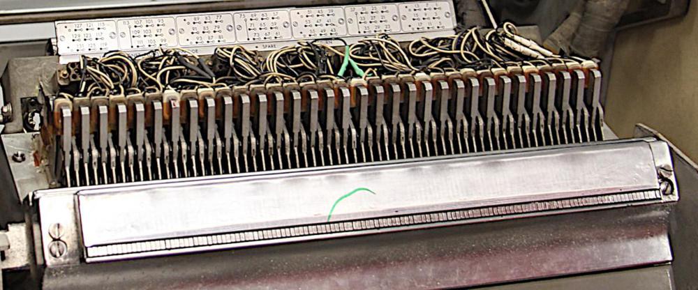
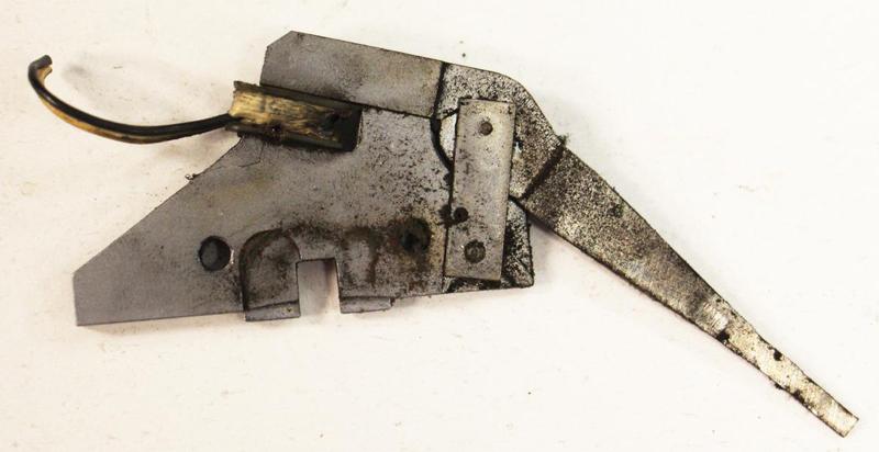
  17. Since the 14 7/8" standardized width is very important, I'll discuss the math in more detail. The 405 accounting machine had 88 type bars, but there was one blank space (for a ribbon guide) between the alphanumeric and numeric type bars. Thus, the printing region was 89 × 5/32" = 13 29/32" wide. (As mentioned before, this just fits (probably by design) onto a 14" unperforated page.) Since standard perforated forms had 1/2" marginal perforations on each side to remove the holes, reasonable form widths would be 14 29/32" or 15". These values are not divisible (hole-to-hole) by 5/32"14. However, since the 402's characters have excessive white space around them, the characters still fit if we trim off 1/32" from the width. This yields a 13 7/8" line. Hole-to-hole, this is 14 3/8", divisible by 5/32" and even better 5/8". Adding the perforated margin, this yields 14 7/8" width as the "best" size to support the 405's 88-character output. (This seemed like random math, even to me, at first. But since the same approach explains the 12 27/32" width, I'm reasonably confident it's the right approach.) 

  18. Why did the 405 accounting machine (1934) and 402 accounting machine (1948) have 88 print positions? The accounting machines had a 43-column alphabetical print unit and a 45-column numeric-only print unit (below), with a 5/32" gap between for the ribbon. I think these type bar print units were derived from the 45-column type bar print unit used for the IBM 550 interpreter (1930), since they have the same 5/32" character spacing. But that raises the question of why two columns are missing from the alphabetical print unit. The 405's line of 88 characters with a gap between the units just fits onto a 14" page. (A 14" page without holes, friction-fed.) This is mentioned in Alphabetic Accounting Machines (1936) page 17-2, so it's presumably deliberate. So I think they used 88 columns instead of 90 in order to fit on 14" paper. 

  19. I talked to an old IBM engineer who serviced a company's collection of 407 tabulators as a new engineer, but after cleaning the type wheels he didn't put enough oil on them. A couple weeks later, the type wheels started seizing up and would hit the platen at high speed, sawing notches into the platen. (The platen is the roller that the paper goes around.) He used up IBM's entire East Coast collection of platens to fix these tabulators. He was afraid IBM would fire him over this, but they were supportive of engineers and he stayed for a long career. 

  20. The design of business forms was a complex task. The book Business Systems Handbook (1979) has a 30-page chapter discussing forms design, including how to meet customer needs, determining the size and layout of the form, and ideas on form techniques for various purposes. 

  21. In the 1970s, IBM still had 11 standard form widths, but there were a couple changes from the 407 era. An IBM patent mentions this in a vague way; apparently the 16 3/4" width was dropped and 11" added. 

  22. The diagram below gives some information on the dimensions of forms for the IBM 407 accounting machine.

    IBM's recommended specifications for forms. From Reference Manual, IBM 407 Accounting Machine.

    IBM's recommended specifications for forms. From Reference Manual, IBM 407 Accounting Machine.

    One important takeaway from this diagram is that the printing width is 1" less than the overall form width. It's interesting to note that the hole width is 5/32", exactly the same as the character width on a 402 accounting machine. 

  23. A width of 13 5/8" gives a printable region of 12 5/8". This fits 120 characters with 5/8" of extra space. A margin makes it easier to align the paper so characters fit between the perforations. Note that a margin is more important with 0.1" characters than 5/32" characters because the wider characters are already surrounded by white space. 

  24. Using 14 7/8" paper gives a printable region of 13 7/8" (13.875"), so you could fit 138 characters on a line. I couldn't find any 138-character printers, but several used 136-character lines. CDC in particular liked 136 columns, as shown by the CDC 501 line printer and later CDC 580. The book Print Unchained. said that 136 columns was a European width, but I haven't been able to find any line printer models fitting this. Later dot matrix printers from Epson, Datapro and other companies often supported 136 columns. 

  25. The timing of the 1403 printer is fairly complicated; I've made an animation here to illustrate it. The important thing for the current discussion is that every third character position gets a chance to print in sequence, so the printer makes three "subscans" to cover all the character positions. Thus, it makes sense for the line length to be a multiple of 3 so all the subscans are equal. Obviously it's possible for the 1403 printer to support a line length that isn't a multiple of 3, since some 1403 printer models supported 100-character lines. 

  26. This may be numerology, but it seems that IBM liked increasing print capacity in steps of 12. On the IBM 285 accounting machine, this made sense since each print bank was 12 characters wide. The IBM 407 accounting machine had 120 columns. The IBM 1443 printer (1962) had line lengths of 120 or 144 characters (2*12 characters more). So it seems plausible that the 132 column line was considered reasonable as it added one more 12-character column. 

  27. You might think that 128 characters per line would be more convenient since it's a power of 2. However, the IBM 1401 was a decimal (BCD) machine with decimal addressing. (For instance, it had 4000 characters of storage, not 4096.) Since it needed to count the line in decimal, there is no hardware advantage to 128. 

  28. To summarize the summary: 88 × 5/32" ≈ 132 × 0.1" (with a bit of margin)