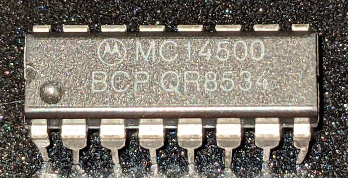
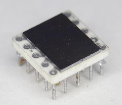
The Motorola MC14500B1 is a 1-bit processor introduced in 1976. While a 1-bit processor might seem almost useless,2 it was marketed as an Industrial Control Unit for applications that made simple decisions based on Boolean logic, for example, air conditioning, motor control, or traffic lights.
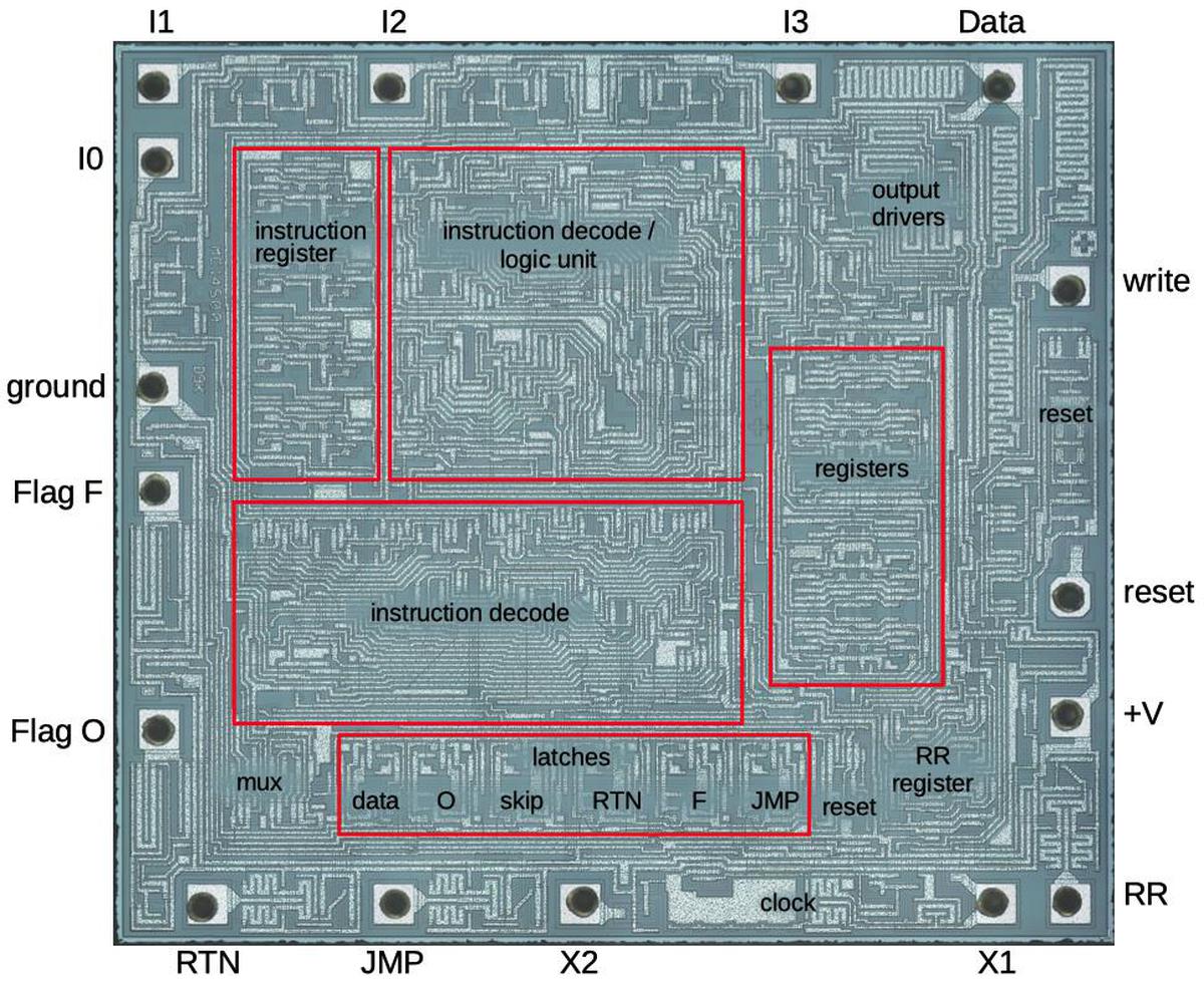
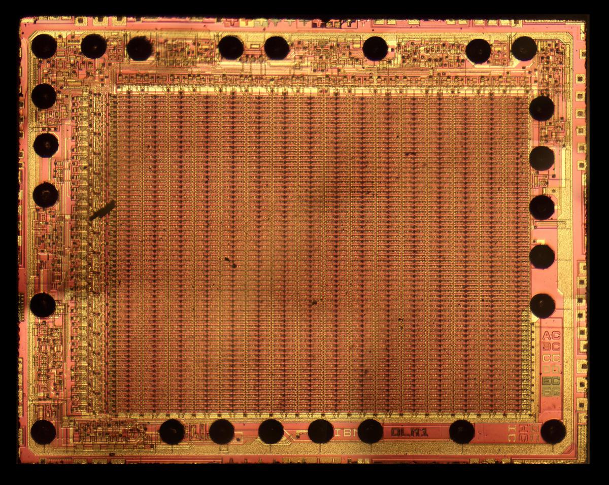
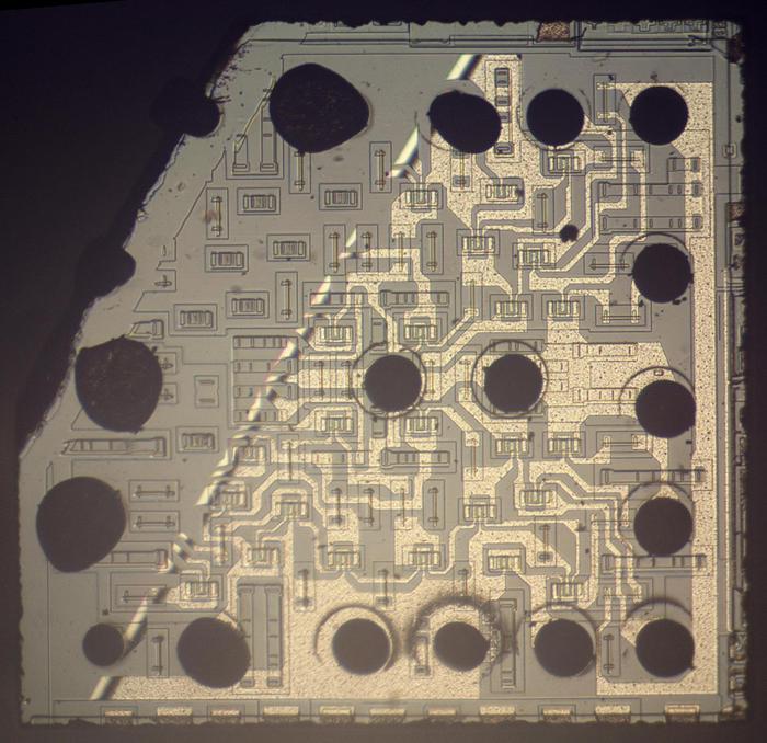
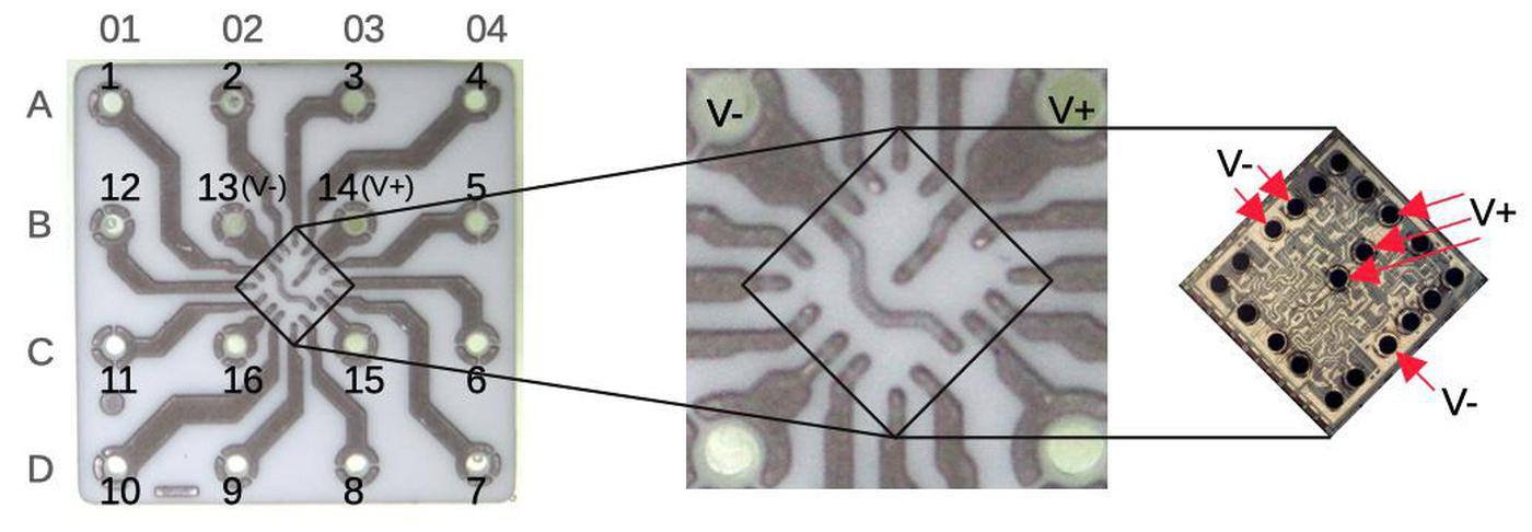
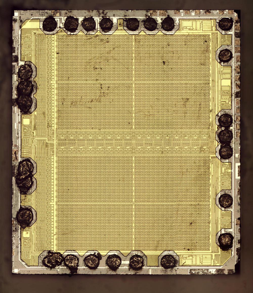
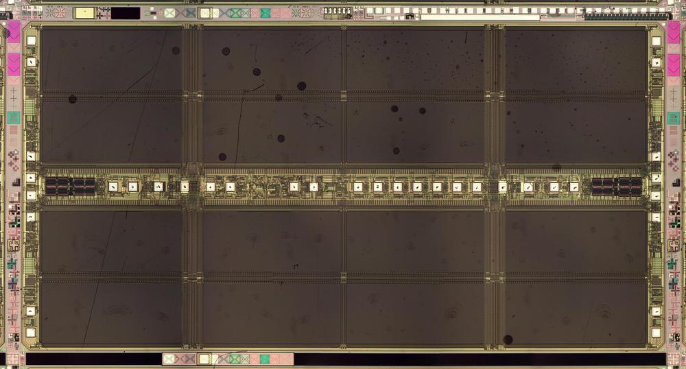
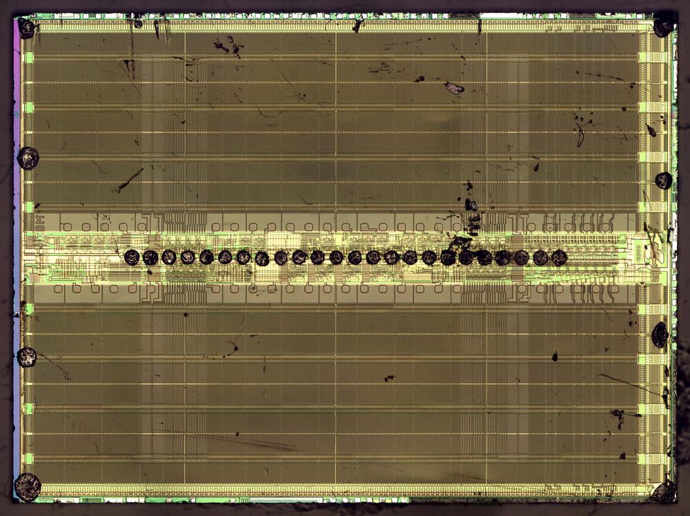
The die photo below shows the processor under a microscope. This silicon appears greenish, while the white lines on top are the metal layer that wires the transistors together. The 16 black spots around the edges are the bond wires that connect the chip to its 16 external pins. The MC14500B has roughly 500 transistors, very few for a microprocessor. In comparison, the popular 8-bit Z-80 microprocessor, also released in 1976, had 8500 transistors. Even the first microprocessor, the 4-bit Intel 4004 (1971), contained 2250 transistors.
You might think that a 1-bit processor would only support two instructions, making it impractical. However, like many processors, the MC14500B uses different sizes for data and instructions. Although it used one bit for data, its instructions were 4 bits, giving it a small but usable instruction set of 16 instructions.3
The MC14500B has an unusual architecture, making it more of a building block than a complete microprocessor. In particular, the chip doesn't include any support for memory or addresses; it didn't even have a program counter. The program counter, instruction fetches, jumps, subroutine calls, and I/O needed to be implemented with external circuitry.4 This is a key reason that the chip was so simple. (The other reason, of course, was that it only supported one bit.)
Since the MC14500B was designed for industrial control applications, you'd expect it to be a microcontroller, but it's the opposite of a microcontroller in many ways. A typical microcontroller is a computer-on-a-chip including RAM and ROM, with strong I/O support, providing a single-chip solution. The MC14500B, however, requires multiple external chips to make it usable.
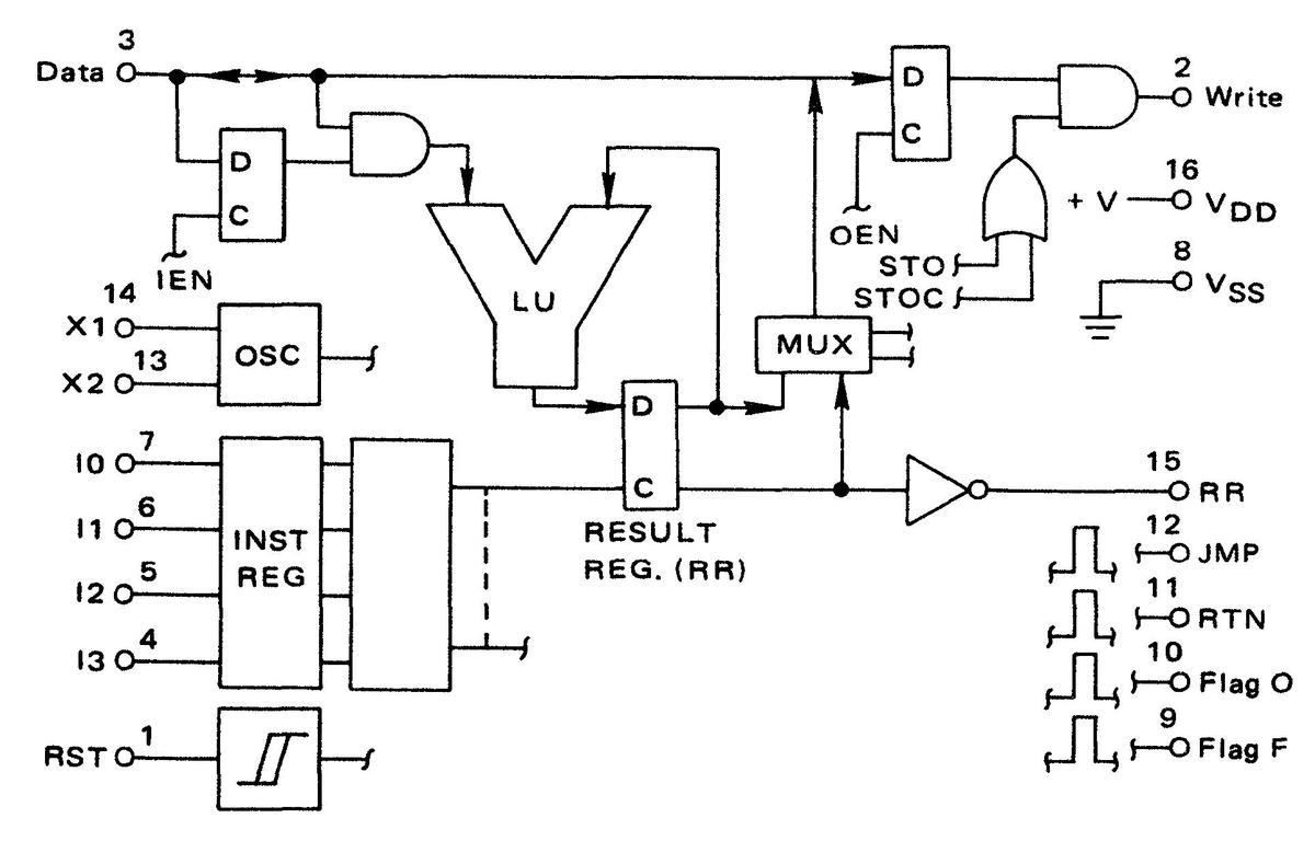
The block diagram below shows the internal structure of the chip. The Data pin in the upper left provides the single-bit I/O line. It feeds into the Logical Unit (LU), which implements 1-bit Boolean logic functions such as AND and OR. The result is stored in the Result Register (RR), the chip's main storage register. The chip has an on-board oscillator OSC that uses an external resistor to control the clock speed. (The chip runs at up to 1 megahertz, faster than I expected.) The Instruction Register stores the 4-bit instruction; the circuitry to decode an instruction occupies the majority of the chip. The JMP, RTN, FLAG O, and FLAG F pins are activated by the corresponding instructions, but the functionality must be implemented externally. Note the lack of a program counter or address pins.
The motivation for making such a stripped-down processor was to provide a low-cost alternative for applications that didn't require a full microprocessor. In 1977, the MC14500B cost $7.58 in quantities of 100 ($32 in current dollars), which seems expensive. However, at the time, an 8080A CPU cost $20 and a Z80 cost $50 ($85 and $215 in current dollars) so there was a significant cost saving to the MC14500B.5 However, the steady fall of processor prices soon made the MC14500B less attractive.
How CMOS logic is implemented
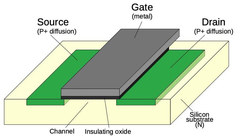
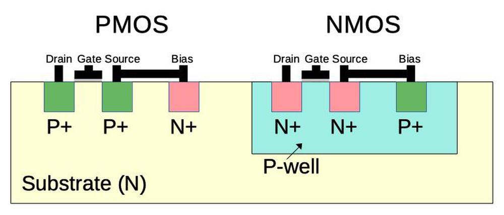
The chip was one of the first processors built from CMOS circuitry,6 a low-power logic family now used in almost all processors. CMOS (complementary MOS) circuitry uses two types of transistors, NMOS and PMOS, working together. The diagram below shows how a PMOS transistor is constructed. The transistor can be considered a switch between the source and drain, controlled by the gate. The source and drain (green) consist of regions of silicon doped with impurities to change its semiconductor properties and called P+ silicon. The gate consists of an aluminum layer, separated from the silicon by a very thin insulating oxide layer.7 (These three layers—Metal, Oxide, Semiconductor—give the MOS transistor its name.) The PMOS transistor turns on when the gate is pulled low.
An NMOS transistor has the opposite construction from PMOS: the source and drain consist of N+ silicon embedded in P silicon. The operation of an NMOS transistor is also opposite from the PMOS transistor: it turns on when the gate is pulled high. Typically PMOS transistors pull the drain (output) high, while NMOS transistors pull the drain low. In CMOS, the transistors act in complementary fashion, pulling the output high or low as needed.
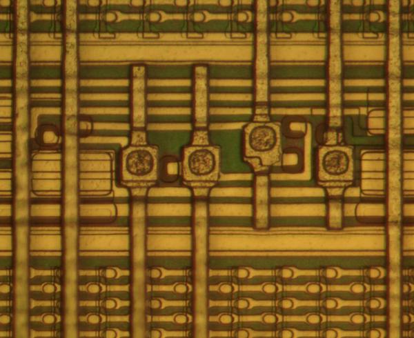
Because the NMOS transistor is built in P silicon, but the silicon die itself is N silicon, the NMOS transistors are surrounded by a tub or well of P silicon. The cross-section diagram below shows how the NMOS transistor on the right is embedded in the well of P-type silicon. The NMOS and PMOS transistors both require a bias voltage connection to the underlying silicon substrate to block signals from escaping from the transistors.8 These bias connections can be seen scattered across the chip.
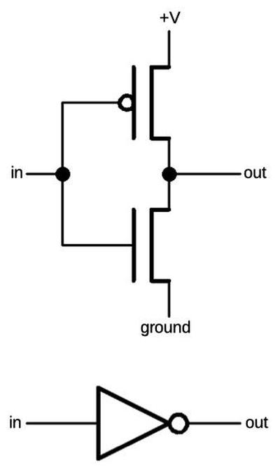
The basic CMOS gate is an inverter, shown below. It is constructed from a PMOS transistor and an NMOS transistor acting in opposite (i.e. complementary) fashion. When the input is low, the PMOS transistor (top) turns on, pulling the output high. When the input is high, the NMOS transistor (bottom) turns on, pulling the output low.
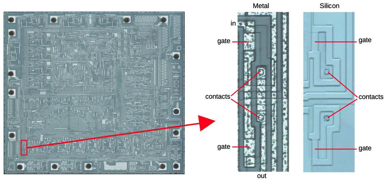
The diagram below shows how an inverter, outlined in red, appears on the die. Note that a single inverter takes a visible part of the die. The next image zooms in on the inverter; the metal wiring is visible as the white lines, while the silicon is mostly obscured. The third image shows the silicon layer after removing the metal with acid. Note how the metal gate lines up with silicon underneath. The circular contacts or vias connect the metal layer to the silicon.
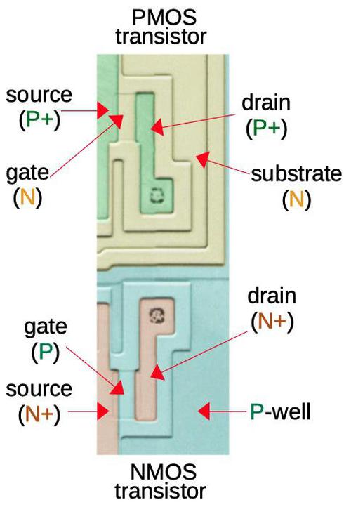
The inverter consists of a PMOS transistor on top and an NMOS transistor below, connected together as described in the schematic earlier. In the diagram below, the silicon regions have been colored to show how they form transistors. Note that the source and drain aren't necessarily discrete, but can merge with neighboring transistors.
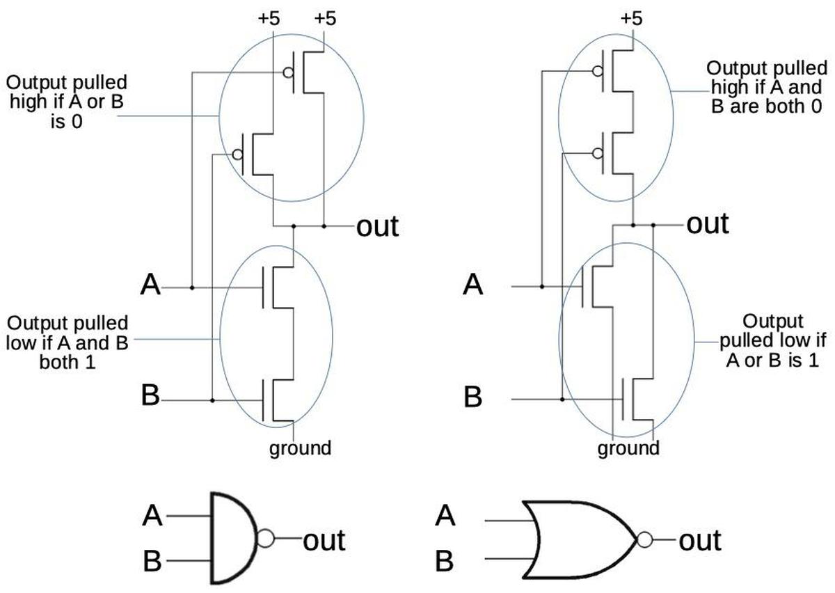
Other logic gates are constructed using the same concepts as the inverter, but with additional transistors. In a NAND gate, the PMOS transistors on top are in parallel, so the output will be pulled high if either input is 0. The NMOS transistors on the bottom are in series, so the output will be pulled low if both inputs are 1. Thus, the circuit implements the NAND function. (Note how the PMOS and NMOS transistors act in complementary fashion.) The NOR gate is implemented similarly, swapping the series and parallel transistors. The chip also uses more complex gates, discussed in the footnote.9
Transmission gate
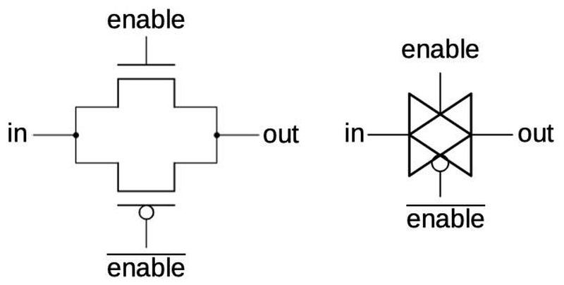
Another key circuit in the processor is the transmission gate. This acts as a switch, either passing a signal through or blocking it. The schematic below shows how a transmission gate is constructed from two transistors, an NMOS transistor and a PMOS transistor. If the enable line is high, both transistors turn on, passing the input signal to the output. If the enable line is low, both transistors turn off, blocking the input signal. The schematic symbol for a transmission gate is shown on the right.
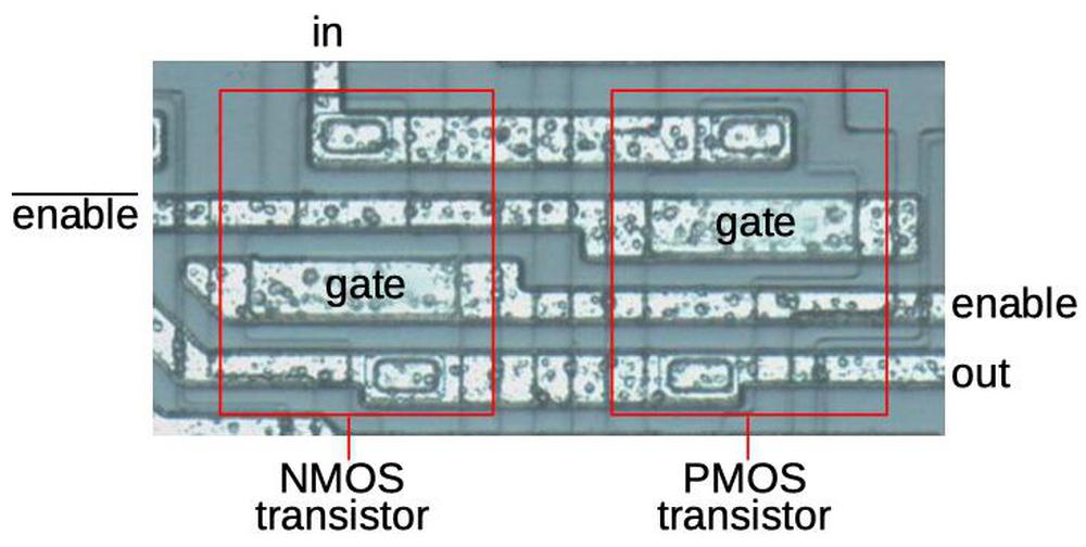
The photo below shows how a transmission gate appears on the die. This photo shows the metal layer, so the underlying silicon is difficult to see. The two transistors are outlined. Note that an inverter has the same input to both gates, so one transistor turns on at a time. In the transmission gate, however, the gates have opposite inputs, so the transistors turn on or off together.
Flip-flop
By combining inverters and transmission gates, an important circuit called the flip-flop is constructed. A flip-flop stores one bit, controlled by a clock signal. The flip-flops have a key role in the chip as they keep the processor synchronized to the clock.
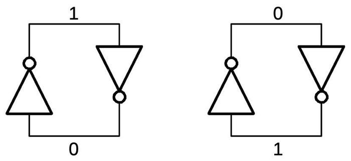
A flip-flop is based on a latch built from two inverters, below By connecting two inverters in a loop, the circuit can store either a 0 or a 1. If the input to an inverter is a 1, it outputs a 0; this causes the other inverter to output a 1, feeding back to the first inverter. Thus, the circuit is stable in either the 0 or 1 state.
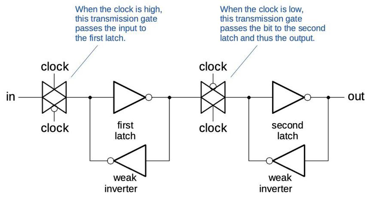
The circuit above requires two changes to form a useful flip-flop. First, it requires a way of storing a value in the latch. This is solved in a brute-force way. One of the inverters uses a weak, low-current transistor.10 An input signal can override this signal, forcing the inverters into the desired state. This input is controlled by a transmission gate: when the gate is active, the input signal is stored in the inverter latch. When the transmission gate is inactive, the inverter latch loop holds the value.
The second change is that two inverter latches are used. The first is controlled by the clock, while the second is controlled by the inverted clock. While the clock is high, the input value passes into the first inverter latch. But when the clock goes low, the transmission gates switch state: the first transmission gate blocks any additional changes, while the second transmission gate passes the value from the first inverter latch to the second latch and thus the output. In effect, the flip-flop grabs the input value when the clock switches low, and holds this output until the next time the clock switches low.
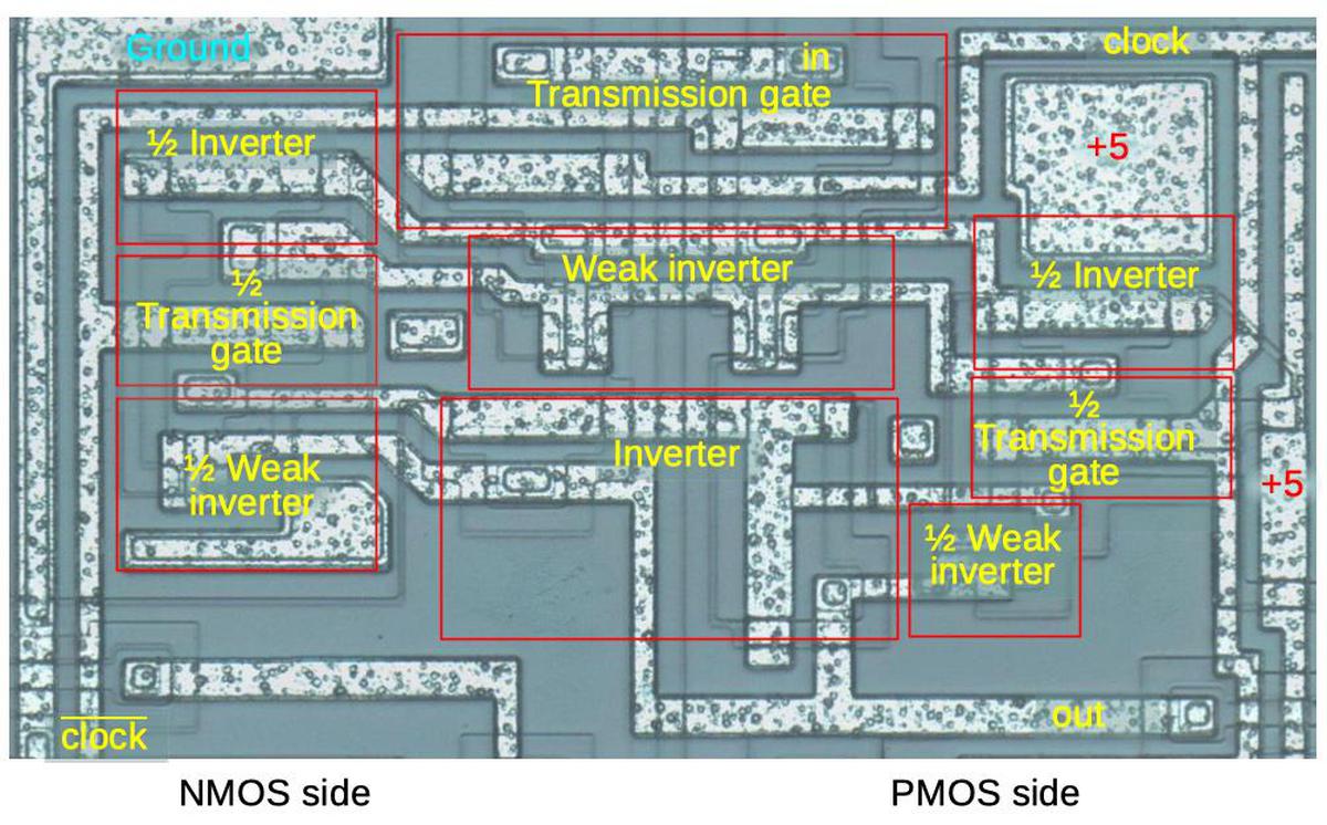
The diagram below shows one of the flip-flops in detail (specifically the instruction register bit I3). It consists of four inverters and two transmission gates, as described earlier but arranged top-to-bottom. The left half consists of the well of P-type silicon for the NMOS transistors, while the right half holds the NMOS transistors. As a result, the inverters and transmission gates have one transistor on each side. This forces some of the gates to have their two transistors widely separated, as seen below.
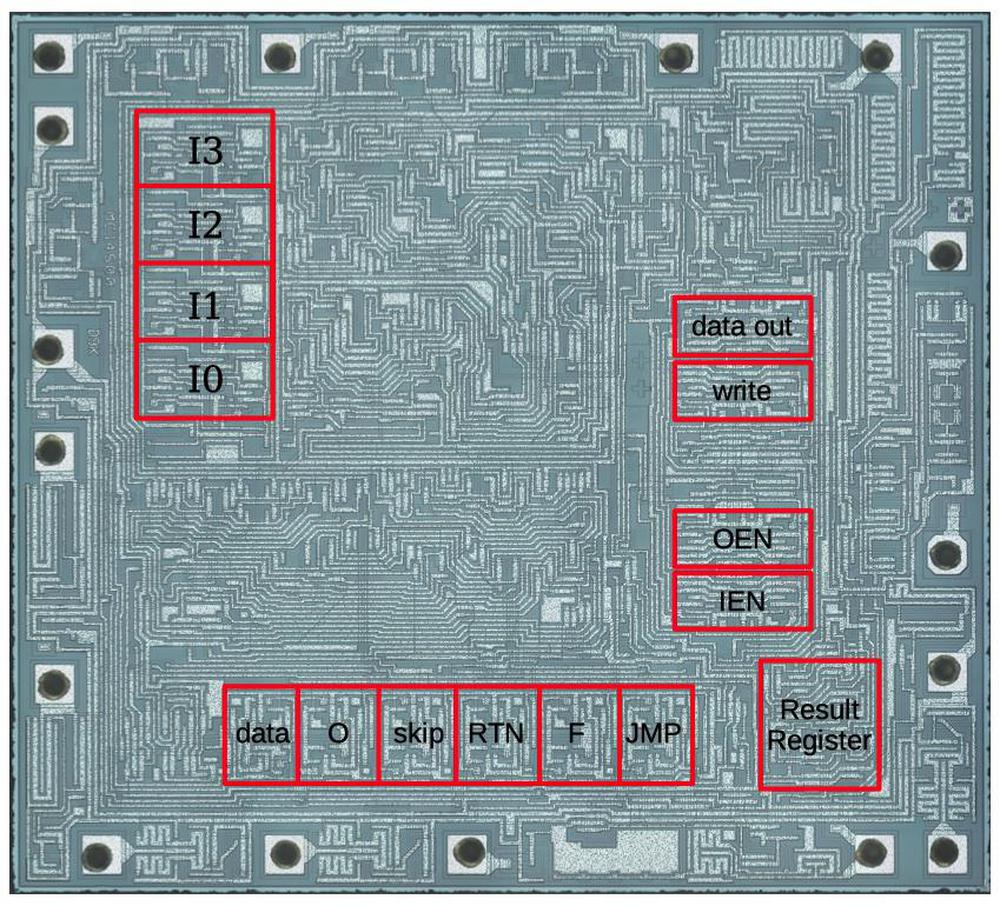
The diagram below shows the locations of the chip's flip-flops. Each flip-flop takes up a substantial part of the chip, despite being the simple circuit described above. This should give you an idea of the small amount of circuitry in the chip. On the left, the 4-bit instruction register consists of four flip-flops. The IEN and OEN registers, as well as two flip-flops to control write operations are on the right. At the bottom, six flip-flops hold the values for the Flag O, RTN, Flag F, and JMP pins, as well as buffering the data mux and holding the instruction skip state. The Result Register (RR) in the lower right is a more complex latch; it has circuitry to hold its existing value as well as a reset circuit.
The logic unit
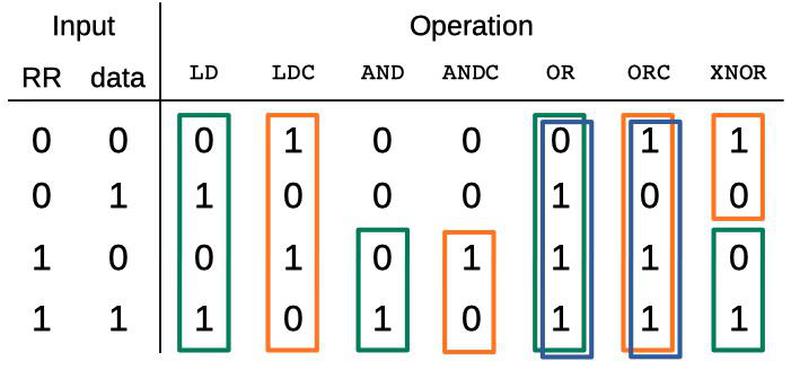
The logic unit (LU) performs 1-bit operations.11 It takes a bit from the data pin, a bit from the RR register, and stores the result in the RR. It implements seven functions: load a bit into the RR, load the complement into the RR, logical AND, logical AND complement, logical OR, logical OR complement, and exclusive NOR. The table below summarizes these operations. Each column shows the results of an operation, for the four possible input combinations.
The colored rectangles indicate how the logic unit is implemented internally. A green rectangle indicates the data value is copied to the output. An orange rectangle indicates the complement of the data value is copied to the output. A blue rectangle indicates that the RR register is OR'd into the result.
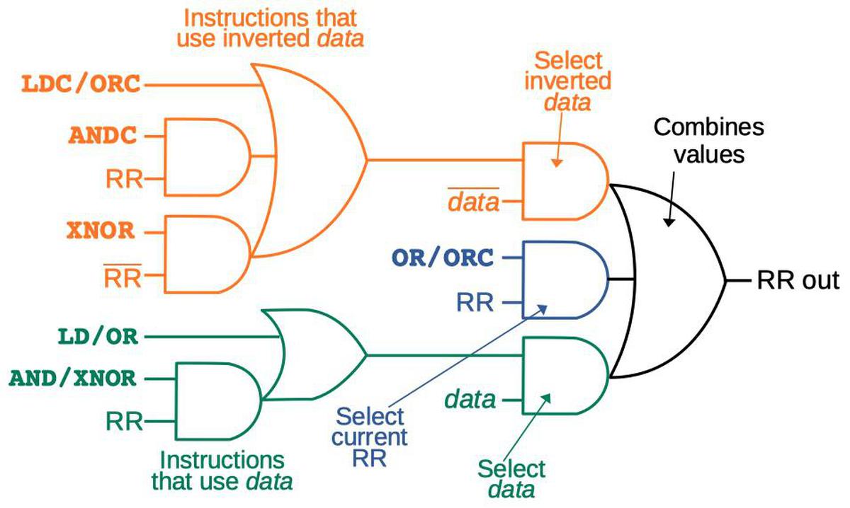
The diagram below shows the three complex logic gates that implement this table. (These are AND-OR-INVERT and OR-AND-INVERT gates, but I've removed the inverters to simplify the explanation.) The appropriate inputs (i.e. colors) are selected based on the instruction and the value of the RR register. The upper-left gate is active for the combinations of instruction and RR value that use the inverted data value (i.e. orange). The lower-left gate is active for the combinations that use data (i.e. green). The right gate selects inverted data, RR, and data as appropriate, and ORs them together to form the final result, stored in the RR register.
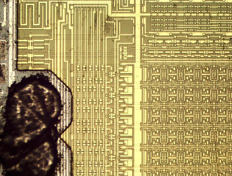
I've looked at a lot of Arithmetic-Logic Units (ALUs) before, and this implementation is rather unusual. The main factor is that it doesn't perform arithmetic operations, so it's not dealing with sums, differences, carry-in, and carry-out. It's also one bit wide, rather than 8 or 16 bits. Due to these factors, it's implemented with the gates shown above, rather than a more typical combination of adders. Another interesting thing about the implementation is that the logic unit's circuitry is mixed in with the instruction decoding circuitry, rather than physically separating the two, as in most processors. (See the die photo at the top of the article.)
Instruction decoding
Much of the chip is devoted to instruction decoding, converting a 4-bit opcode into an instruction signal. Although many microprocessors, such as the 6502, use a Programmable Logic Array (PLA) for instruction decoding, the MC14500B doesn't use anything structured like that. Instead, it just has a bunch of gates. First, it decodes pairs of instruction bits (bit 0 with bit 1, and bit 2 with bit 3) into their combinations. Then it combines these signals for the full decoding.
For instance, one signal is generated if instruction bits I3 and I2 are high, by NOR of I3' and I2'. Another signal is generated if I1 is high and I0 is low, by NOR of I1' and I0. Combining these two signals with a NAND gate generates a signal that is low for the SKZ (skip on zero) instruction which has the opcode 1110. This signal is fed into the instruction skip circuitry to implement the instruction. The other instructions are decoded by similar combinations of gates.
Control flow
The MC14500B uses several techniques to provide control flow in programs.
Its conditional instruction is SKZ, which skips the next instruction if the RR register is zero.
The chip implements the skip instruction by setting a flip-flop if the next instruction should be skipped.
If so, the next instruction is overridden by the opcode 0000 through some gates on the instruction pins.
This opcode corresponds to the NOP O instruction. This instruction normally energizes the O pin, but the skip circuit suppresses this too.
The result is that the skip circuit suppresses the next instruction, and then execution continues.
The chip has opcodes for jump (JMP) and return from subroutine (RTN). These instructions don't do much other than energizing
the JMP or RTN pins.12 These operations must be implemented by external circuitry if desired.
The chip provides an unusual technique for implementing larger conditional code blocks. Write operations are controlled by the OEN (Output ENable) flip-flop. To suppress a block of code, the OEN flip-flop can be cleared. The code will still be executed, but it won't have any effect since the output is disabled, so it acts like an IF-THEN block. Similarly, the IEN (Input Enable) instruction will disable the input. These instructions provide conditional execution even if the hardware isn't implemented for the jump instruction.
Finally, a recommended implementation is to wire the F pin to the program counter's reset line. Then, the NOP F instruction will cause the program counter to return to the start of the code. This permits a processing loop to be implemented very simply.
Conclusion
The MC14500B processor is simple enough that its circuitry can be reverse-engineered and understood. To summarize the chip's operations, it takes a 4-bit instruction, which is stored in the instruction register (four flip-flops) and then decoded (using a large number of gates). A logic instruction takes a value from the RR register and the data pin. The "Logic Unit" uses three complex gates in a clever arrangement to perform the selected Boolean operation, and the result is stored back in the RR register. The processor has other flip-flops to handle write operations and other instructions. Execution is controlled by the on-chip clock.
The MC14500B is an unusual processor, handling just one bit of data, while off-loading functionality such as the program counter. Although a one-bit processor might seem like a joke at first, it had genuine uses for implementing logic-based industrial controllers. It seems like an evolutionary dead-end, though. Larger 4-bit and 8-bit microcontrollers were very popular, while the MC14500B was a niche product.
Thanks to David of Usagi Electric for driving the MC14500B analysis project and thanks to John McMaster for decapping the chips and creating the MC14500B images (CC BY 4.0). I first heard about the MC14500B from jonsen back in 2013. I announce my latest blog posts on Twitter, so follow me @kenshirriff. I also have an RSS feed.
Notes and references
-
You might wonder why the MC14500B ends with a "B". Motorola used the B suffix to indicate a buffered chip, while UB indicated an unbuffered chip. For instance, the MC14001UB NOR gate took its output directly from the NOR circuit, while the MC14001B added a double-inverter buffering stage to the output. The buffering stage provided better noise immunity, but the unbuffered chips were faster and better for semi-analog circuits such as oscillators. (See Motorola 1978 Databook p4-3 for discussion.) Motorola was often haphazard with using the B suffix on their part numbers. However, Motorola also used MC14500 to refer to a family of assorted CMOS chips, so the "B" was necessary to distinguish between the MC14500 family and the MC14500B processor chip. Thus, Motorola never used MC14500 without the suffix to refer to the processor chip, as far as I can tell.
Also see A Strong Commitment to Complementary MOS (1972), an interesting article from when CMOS was just starting its growth, and it was unclear how successful it would be. In this article, Motorola described its line of CMOS products, which it called "McMOS". Motorola had the 14000 series of standard parts, and the 14500 series for newer, more complex designs. Thus, the 14500 series included parts such as the MC14501 triple gate, MC14514 latch/decoder, and the MC14518 dual up counters.
For more information on the MC14500B processor, see the datasheet and the detailed MC14500B handbook. ↩
-
Note that the MC14500B is not a bit-slice processor, but intended for 1-bit applications. The idea of a bit-slice processor is that the processor chip is designed for 2 or 4 bits, for example, but you combine multiple chips to build a 16-bit processor, for instance. Each processor handles a slice of the complete word. Many systems were built in the 1970s with bit-slice processors such as the Am2901. Bit-slice processors were popular when an individual chip couldn't hold the circuitry for a complete processor, so it needed to be partitioned across multiple chips. ↩
-
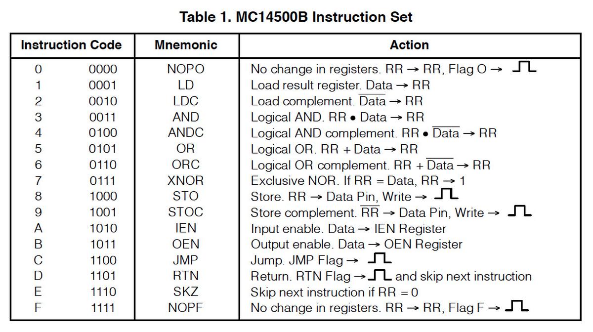
The table below gives the full instruction set for the MC14500B. It uses a 4-bit instruction so it has 16 different instructions.
The MC14500B instruction set. From the datasheet. -
The MC14500B omitted a lot of circuitry that you expect to find in a processor, requiring it to be implemented separately. While the chip has opcodes for Jump and Subroutine Return, it doesn't do anything other than activate an external pin for those instructions; supporting subroutines required an external chip. The chip has a single data in/out pin; that pin is typically connected to multiple I/O devices with an external multiplexer/demultiplexer. Finally, while the chip itself has a 4-bit instruction set, a system typically added more instruction bits to address I/O devices or memory. A full system could use 8-bit instructions with four bits going to the processor and four bits selecting the I/O port or storage location. Alternatively, the system could use a larger program counter, more instruction bits, or external RAM depending on the application.
Motorola sold chips that could work with the MC14500B to build a complete system. The MC14512 Input Selector could multiplex eight inputs into the processor, while the MC14599B Output Latch provided eight outputs or eight bits of storage. The program counter could be implemented by an MC14516B Program Counter (a 4-bit up/down counter chip) or two. ↩
-
The 8-bit HP Nanoprocessor from 1974 was another low-cost, minimal processor. However, it was more complex than the MC14500B with about 10 times as many transistors. The Nanoprocessor included a program counter, subroutine support, and multiple registers. Like the MC14500B, the Nanoprocessor omitted arithmetic operations. ↩
-
Early CMOS microprocessors include the 12-bit Intersil 6100 (1974) and the 8-bit RCA 1802 COSMAC (1974). The 1802 is said to be the first CMOS microprocessor. Mainstream microprocessors didn't switch to CMOS until the mid-1980s. ↩
-
The MC14500B used metal-gate transistors, with aluminum forming the transistor gate. These transistors were not as advanced as the silicon-gate transistors that were developed in the late 1960s. Silicon gate technology was much better in several ways. First, silicon-gate transistors were smaller, faster, and more reliable. Second, silicon-gate chips had a layer of polysilicon wiring in addition to the metal wiring; this made chip layouts about twice as dense. In comparison, many of the signals on the MC14500B have long, winding paths in the metal layer due to the difficulties of routing with a single metal layer. The Intel 4004 used silicon gates in 1971, so the MC14500B was far behind technologically to use metal gates in 1976. I assume this was done for cost reasons. ↩
-
The bias voltage makes the boundary between a transistor and the substrate act as a reverse-biased diode, so current can't flow across the boundary. Specifically, for a PMOS transistor, the N-silicon substrate is connected to +5 volts. For an NMOS transistor, the P-silicon well is connected to ground. A P-N junction acts as a diode, with current flowing from P to N. But the bias voltages put P at ground and N at +5, blocking any current flow. The result is that the substrate can be considered an insulator, with current restricted to the N+ and P+ doped regions (to simplify a bit). ↩
-
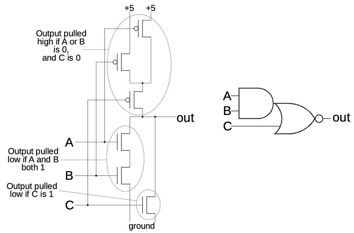
More complex gates can be created by combining transistors in series and parallel. The AND-OR-INVERT gate below is an example. Because of the way CMOS works, this gate is constructed as a single gate (rather than three); it's no more difficult to make it than a NAND gate. CMOS gates, however, require inversion on the output, so you can't make an AND or OR gate directly.
An AND-OR-INVERT gate implemented with CMOS. -
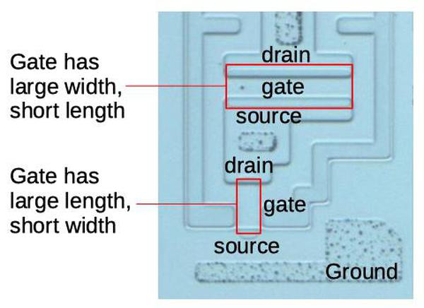
The current that a transistor can provide is proportional to the ratio between the gate length (the distance between the source and drain) and the gate width. The diagram below shows two transistors, a strong one on top and a weak one below. The strong transistor has a wide gate so it can provide a relatively high current. (Imagine slicing the transistor into parallel transistors, each one providing current.) The weak transistor has a narrow, but long gate, so it provides a much smaller current. (Think of the current needing to travel a longer distance through the current-blocking gate.) Based on the ratio of sizes, the upper transistor will pass about 16 times as much current as the lower transistor.
The top transistor is a strong transistor, while the bottom transistor is a weak transistor. This photo shows the silicon after dissolving the metal layer. -
The processor has a logic unit (LU), not an arithmetic/logic unit (ALU), because it doesn't perform any arithmetic operations. The handbook (chapter 14) explains how you can use the chip's logic instructions to do arithmetic if you really need to; it takes 12 operations to do a 1-bit add, repeated N times for an N-bit addition. ↩
-
The return from subroutine instruction (RTN) causes the next instruction to be skipped. The motivation is that external circuitry can push the current address on the stack when doing a subroutine call. When popped for a return, this address will still point to the subroutine call instruction. By skipping the instruction after a return, the MC14500B avoids an infinite loop. (The external circuitry could, of course, increment the return address but that would have required more hardware.) ↩
