Reverse engineering CMOS, illustrated with a vintage Soviet counter chip

I recently came across an interesting die photo of a Soviet1 chip, probably designed in the 1970s. This article provides an introductory guide to reverse-engineering CMOS circuits, using this chip as an example. Although the chip looks like a tangle of lines at first, its large features and simple layout make it possible to understand its circuits. I'll first explain how to recognize the individual transistors. Groups of transistors are connected in standard patterns to form CMOS gates, multiplexers, flip-flops, and other circuits. Once these building blocks are understood, reverse-engineering the full chip becomes practical. The chip turned out to be a 4-bit CMOS counter, a copy of the Motorola MC14516B.

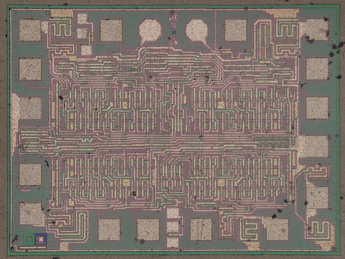
Die photo of the К561ИЕ11 chip on a wafer. Image courtesy of Martin Evtimov. Click this image (or any other) for a larger version.

Die photo of the К561ИЕ11 chip on a wafer. Image courtesy of Martin Evtimov. Click this image (or any other) for a larger version.

The photo above shows the tiny silicon die under a microscope. Regions of the silicon are doped with impurities to change the silicon's electrical properties. This doping also causes regions of the silicon to appear greenish or reddish, depending on how a region is doped. (These color changes will turn out to be useful for reverse engineering.) On top of the silicon, the whitish metal layer is visible, forming the chip's connections. This chip uses metal-gate transistors, an old technology, so the metal layer also forms the gates of the transistors. Around the outside of the chip, the 16 square bond pads connect the chip to the outside world. When installed in a package, the die has tiny bond wires between the pads and the lead frame, the metal structure that connects to the chip's pins.

According to the Russian datasheet,2 the chip has 319 "elements", presumably counting the semiconductor devices. The chip has a handful of diodes to protect the inputs, so the total transistor count is a bit over 300. This transistor count is nothing compared to a modern CMOS processor with tens of billions of transistors, of course, but most of the circuit principles are the same.

NMOS and PMOS transistors

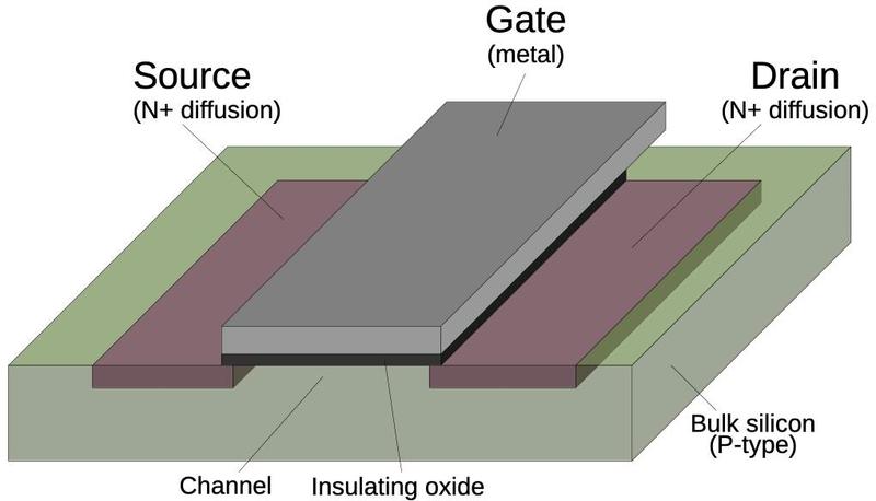
CMOS is a low-power logic family now used in almost all processors.3 CMOS (complementary MOS) circuitry uses two types of transistors, NMOS and PMOS, working together. The diagram below shows how an NMOS transistor is constructed. The transistor can be considered a switch between the source and drain, controlled by the gate. The source and drain regions (red) consist of silicon doped with impurities to change its semiconductor properties, forming N+ silicon. The gate consists of an aluminum layer, separated from the silicon by a very thin insulating oxide layer.4 (These three layers—Metal, Oxide, Semiconductor—give the MOS transistor its name.) This oxide layer is an insulator, so there is essentially no current flow through the gate, one reason why CMOS is a low-power technology. However, the thin oxide layer is easily destroyed by static electricity, making MOS integrated circuits sensitive to electrostatic discharge.

Structure of an NMOS transistor.

Structure of an NMOS transistor.

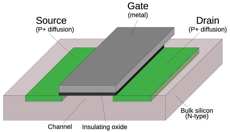
A PMOS transistor (below) has the opposite configuration from an NMOS transistor: the source and drain are doped to form P+ regions, while the underlying bulk silicon is N-type silicon. The doping process is interesting, but I'll leave the details to a footnote.5

Structure of a PMOS transistor.

Structure of a PMOS transistor.

The NMOS and PMOS transistors are opposite in their construction and operation; this is the "Complementary" in CMOS. An NMOS transistor turns on when the gate is high, while a PMOS transistor turns on when the gate is low. An NMOS transistor is best at pulling its output low, while a PMOS transistor is best at pulling its output high. In a CMOS circuit, the transistors work as a team, pulling the output high or low as needed. The behavior of MOS transistors is complicated, so this description is simplified, just enough to understand digital circuits.

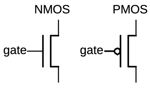
If you buy an MOS transistor from an electronics supplier, it comes as a package with three leads for the source, gate, and drain. The source and drain are connected differently inside the package and are not interchangeable in a circuit. In an integrated circuit, however, the transistor is symmetrical and the source and drain are the same. For that reason, I won't distinguish between the source and the drain in the following discussion. I will use the symmetrical symbols below for NMOS and PMOS transistors; the inversion bubble on the PMOS gate symbolizes that a low signal activates the PMOS transistor.

Symbols for NMOS and PMOS transistors.

Symbols for NMOS and PMOS transistors.

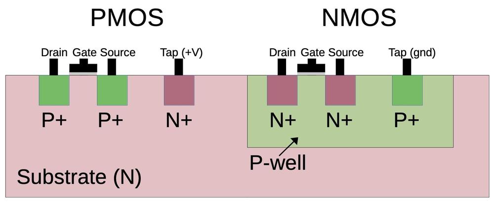
One complication is that NMOS transistors are built on P-type silicon, while PMOS transistors are built on N-type silicon. Since the silicon die itself is N silicon, the NMOS transistors need to be surrounded by a tub or well of P silicon.6 The cross-section diagram below shows how the NMOS transistor on the right is embedded in the well of P-type silicon. Constructing two transistor types with opposite behaviors makes manufacturing more complex, one reason why CMOS took years to catch on. CMOS was invented in 1963 at Fairchild Semiconductor, but RCA was the main proponent of CMOS, commercializing it in the late 1960s. Although RCA produced a CMOS microprocessor in 1974, mainstream microprocessors didn't switch to CMOS until the mid-1980s with chips such as the Motorola 68020 (1984) and the Intel 386 (1986).

Cross-section of CMOS transistors.

Cross-section of CMOS transistors.

For proper operation, the silicon that surrounds transistors needs to be connected to the appropriate voltage through "tap" contacts.7 For PMOS transistors, the substrate is connected to power through the taps, while for NMOS transistors the well region is connected to ground through the taps. When reverse-engineering, the taps can provide important clues, indicating which regions are NMOS and which are PMOS. As will be seen below, these voltages are also important for understanding the circuitry of this chip.

The die photo below shows two transistors as they appear on the die. The appearance of transistors varies between different integrated circuits, so a first step of reverse engineering is determining how they look in a particular chip. In this IC, a transistor gate can be distinguished by a large rectangular region over the silicon. (In other metal-gate transistors, the gate often has a "bubble" appearance.) The interactions between the metal wiring and the silicon can be distinguished by subtle differences. For the most part, the metal wiring passes over the silicon, isolated by thick insulating oxide. A contact between metal and silicon is recognizable by a smaller oval region that is slightly darker; wires are connected to the transistor sources and drains below. MOS transistors often don't have discrete boundaries; as will be seen later, the source of one transistor can overlap with the drain of another.

Two transistors on the die.

Two transistors on the die.

Distinguishing PMOS and NMOS transistors can be difficult. On this chip, P-type silicon appears greenish, and N-type silicon appears reddish. Thus, PMOS transistors appear as a green region surrounded by red, while NMOS is the opposite. Moreover, PMOS transistors are generally larger than NMOS transistors because they are weaker. Another way to distinguish them is by their connection in circuits. As will be seen below, PMOS transistors in logic gates are connected to power while NMOS transistors are connected to ground.

Metal-gate transistors are a very old technology, mostly replaced by silicon-gate transistors in the 1970s. Silicon-gate circuitry uses an additional layer of polysilicon wiring. Moreover, modern ICs usually have more than one layer of metal. The metal-gate IC in this post is easier to understand than a modern IC, since there are fewer layers to analyze. The CMOS principles are the same in modern ICs, but the layout will appear different.

Implementing an inverter in CMOS

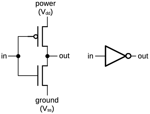
The simplest CMOS gate is an inverter, shown below. Although basic, it illustrates most of the principles of CMOS circuitry. The inverter is constructed from a PMOS transistor on top to pull the output high and an NMOS transistor below to pull the output low. The input is connected to the gates of both transistors.

A CMOS inverter is constructed from a PMOS transistor (top) and an NMOS transistor (bottom).

A CMOS inverter is constructed from a PMOS transistor (top) and an NMOS transistor (bottom).

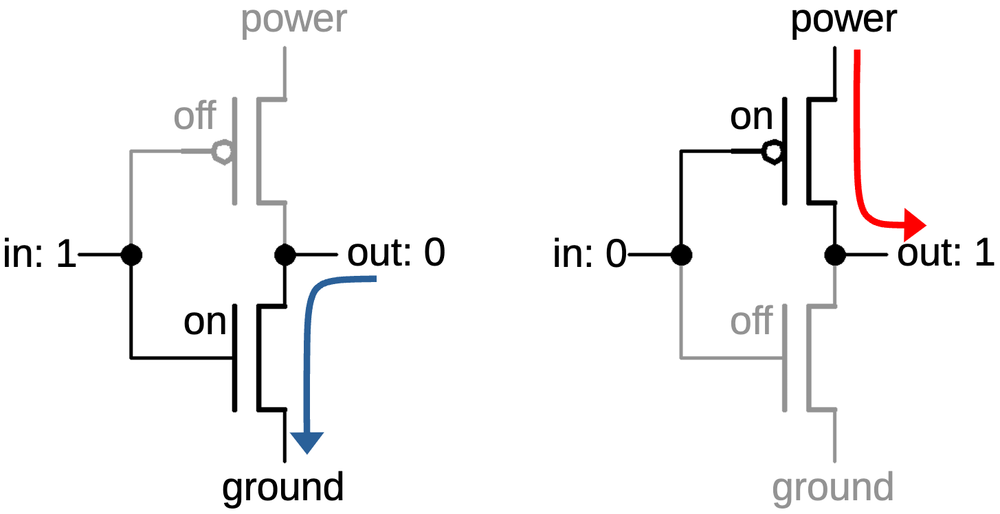
Recall that an NMOS transistor is turned on by a high signal on the gate, while a PMOS transistor is the opposite, turned on by a low signal. Thus, when the input is high, the NMOS transistor (bottom) turns on, pulling the output low. When the input is low, the PMOS transistor (top) turns on, pulling the output high. Notice how the transistors act in opposite (i.e. complementary) fashion.

How the inverter functions.

How the inverter functions.

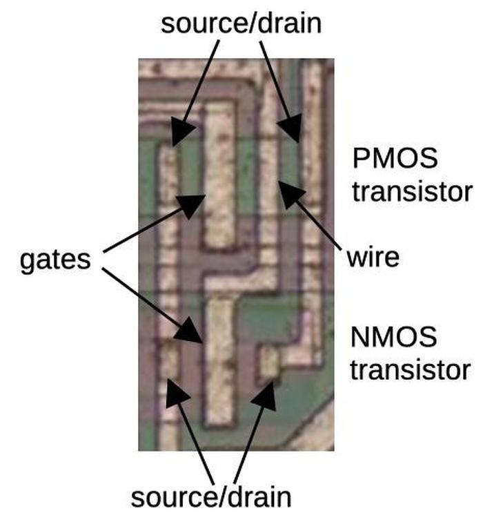
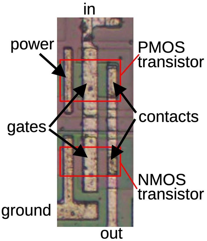
An inverter on the die is shown below. The PMOS and NMOS transistors are indicated by red boxes and the transistors are connected according to the schematics above. The input is connected to the gates of the two transistors, which can be distinguished as larger metal rectangles. On the right, two contacts connect the transistor drains to the output. The power and ground connections are a bit different from most chips since the metal lines appear to not go anywhere. The short metal line labeled "power" connects the PMOS transistor's source to the substrate, the reddish silicon that surrounds the transistor. As described earlier, the substrate is connected to the chip's power. Thus, the transistor receives its power through the substrate silicon. This approach isn't optimal, due to the relatively high resistance of silicon, but it simplifies the wiring. Similarly, the ground metal connects the NMOS transistor's source to the well that surrounds the transistor, P-type silicon that appears green. Since the well is grounded, the transistor has its ground connection.

An inverter on the die.

An inverter on the die.

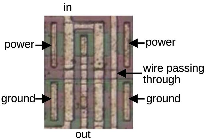
Some inverters look different from the layout above. Many of the chip's inverters are constructed as two inverters in parallel to provide twice the output current. This gives the inverter more "fan-out", the ability to drive the inputs of a larger number of gates.8 The diagram below shows a doubled inverter, which is essentially the previous inverter mirrored and copied, with two PMOS transistors at the top and two NMOS transistors at the bottom. Note that there is no explicit boundary between the paired transistors; their drains share the same silicon. Consequently, each output contact is shared between two transistors, rather than being duplicated.

An inverter consisting of two inverters in parallel.

An inverter consisting of two inverters in parallel.

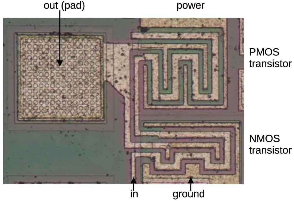
Another style of inverter drives the chip's output pins. The output pins require high current to drive external circuitry. The chip uses much larger transistors to provide this current. Nonetheless, the output driver uses the same inverter circuit described earlier, with a PMOS transistor to put the output high and an NMOS transistor to pull the output low. The photo below shows one of these output inverters on the die. To fit the larger transistors into the available space, the transistors have a serpentine layout, with the gate winding between the source and the drain. The inverter's output is connected to a bond pad. When the die is mounted in a package, tiny bond wires connect the pads to the external pins.

An output driver is an inverter, built with much larger transistors.

An output driver is an inverter, built with much larger transistors.

NOR and NAND gates

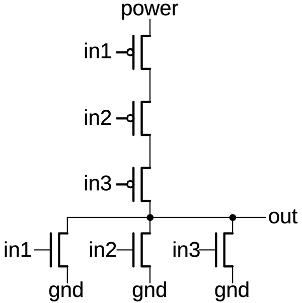
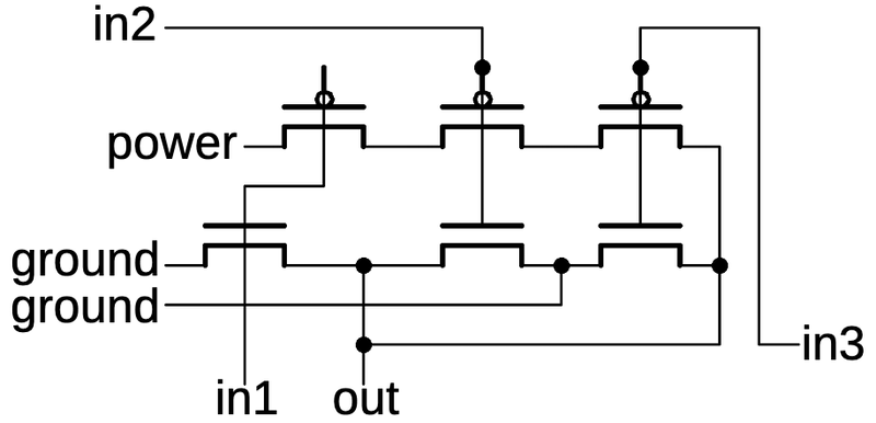
Other logic gates are constructed using the same concepts as the inverter, but with additional transistors. In a NOR gate, the PMOS transistors on top are in series, so the output will be pulled high if all inputs are 0. The NMOS transistors on the bottom are in parallel, so the output will be pulled low if any input is 1. Thus, the circuit implements the NOR function. Again, note the complementary action: the PMOS transistors pull the output high, while the NMOS transistors pull the output low. Moreover, the PMOS transistors are in series, while the NMOS transistors are in parallel. The circuit below is a 3-input NOR gate; different numbers of inputs are supported similarly. (With just one input, the circuit becomes an inverter, as you might expect.)

A 3-input NOR gate implemented in CMOS.

A 3-input NOR gate implemented in CMOS.

For any gate implementation, the input must be either pulled high by the PMOS side, or pulled low by the NMOS side. If both happen simultaneously for some input, power and ground would be shorted, possibly destroying the chip. If neither happens, the output would be floating, which is bad in a CMOS circuit.9 In the NOR gate above, you can see that for any input the output is always pulled either high or low as required. Reverse engineering tip: if the output is not always pulled high or low, you probably made a mistake in either the PMOS circuit or the NMOS circuit.10

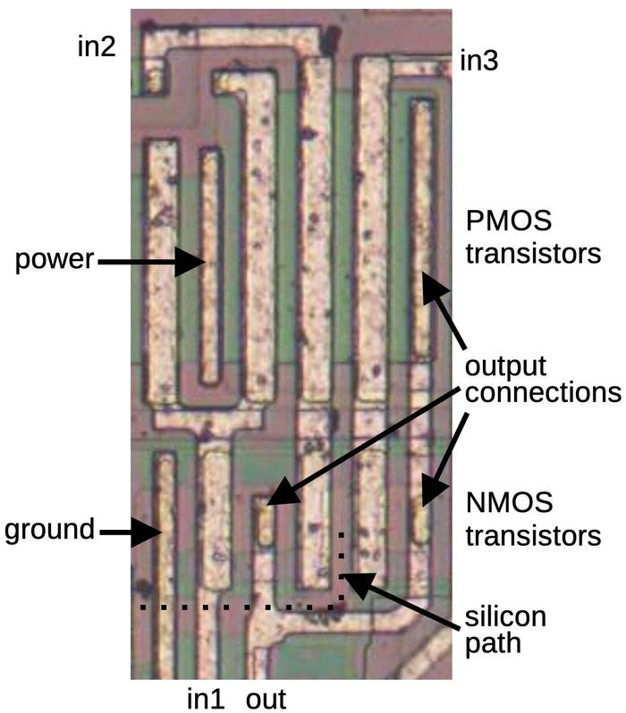
The diagram below shows how a 3-input NOR gate appears on the die.11 The transistor gates are the thick vertical metal rectangles; PMOS transistors are on top and NMOS below. The three PMOS transistors are in series between power on the left and the output connection on the right. As with the inverter, the power and ground connections are wired to the bulk silicon, not to the chip's power and ground lines.

A 3-input NOR gate as it is implemented on the die. The "extra" PMOS transistor on the left is part of a different gate.

A 3-input NOR gate as it is implemented on the die. The "extra" PMOS transistor on the left is part of a different gate.

The layout of the NMOS transistors is more complicated because it is difficult to wire the transistors in parallel with just one layer of metal. The output wire connects between the first and second transistors as well as to the third transistor. An unusual feature is the connection of the second and third NMOS transistors to ground is done by a horizontal line of doped silicon (reddish "silicon path" indicated by the dotted line). This silicon extends from the ground metal to the region between the two transistors. Finally, note that the PMOS transistors are much larger than the NMOS transistors. This is both because PMOS transistors are inherently less efficient and because transistors in series need to be lower resistance to avoid degrading the output signal. Reverse-engineering tip: It's often easier to recognize the transistors in series and then use that information to determine which transistors must be in parallel.

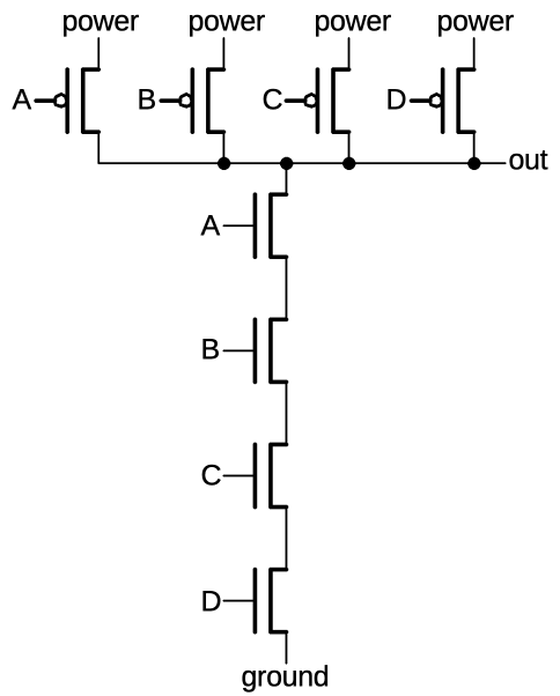
A NAND gate is implemented by swapping the roles of the series and parallel transistors. That is, the PMOS transistors are in parallel, while the NMOS transistors are in series. For example, the schematic below shows a 4-input NAND gate. If all inputs are 1, the NMOS transistors will pull the output low. If any input is a 0, the corresponding PMOS transistor will pull the output high. Thus, the circuit implements the NAND function.

A 4-input NAND gate implemented in CMOS.

A 4-input NAND gate implemented in CMOS.

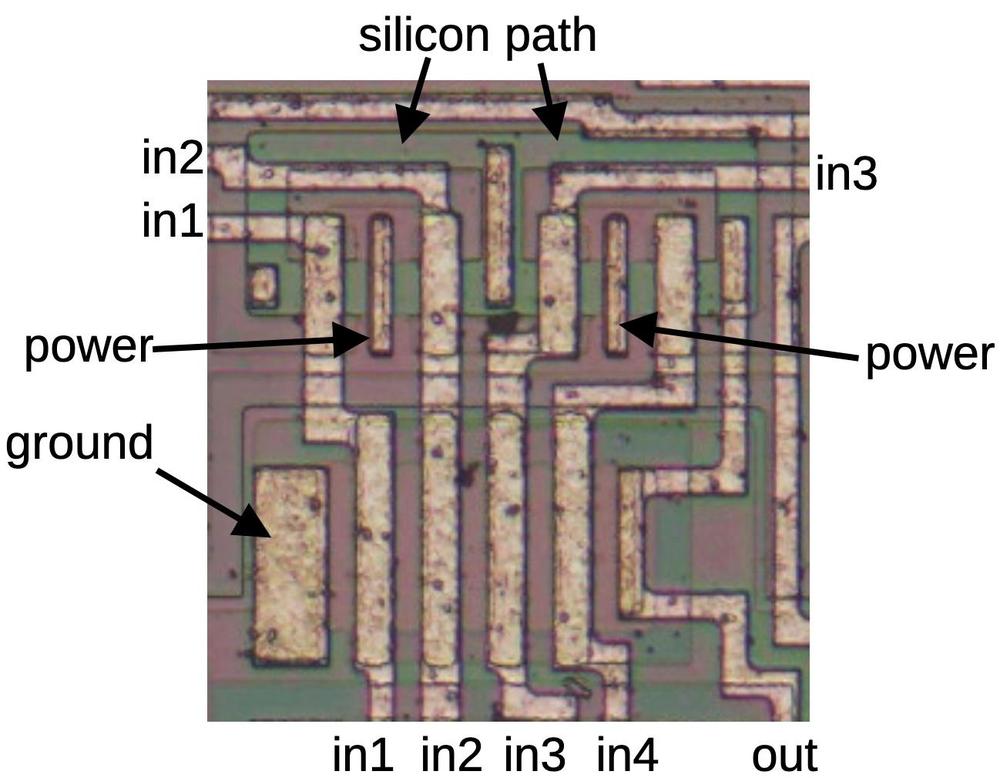
The diagram below shows a four-input NAND gate on the die. In the bottom half, four NMOS transistors are in series, while in the top half, four PMOS transistors are in parallel. (Note that the series and parallel transistors are switched compared to the NOR gate.) As in the NOR gate, the power and ground are provided by metal connections to the bulk silicon (two connections for the power). The parallel PMOS circuit uses a "silicon path" (green) to connect each transistor to the output without intersecting the metal. In the middle, this silicon has a vertical metal line on top; this reduces the resistance of the silicon path. The NMOS transistors are larger than the PMOS transistors in this case because the NMOS transistors are in series.

A four-input NAND gate as it appears on the die.

A four-input NAND gate as it appears on the die.

Complex gates

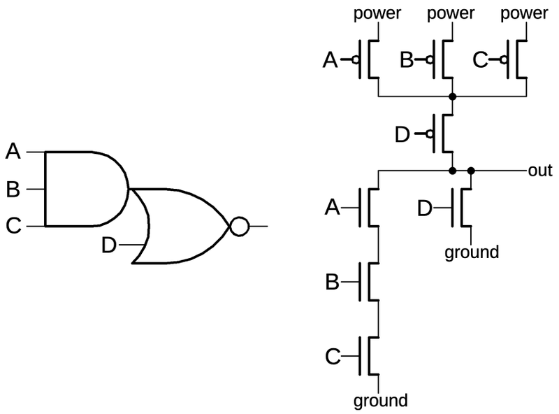
More complex gates such as AND-NOR (AND-OR-INVERT) can also be constructed in CMOS; these gates are commonly used because they are no harder to build than NAND or NOR gates. The schematic below shows an AND-NOR gate. To understand its construction, look at the paths to ground through the NMOS transistors. The first path is through A, B, and C. If these inputs are all high, the output is low, implementing the AND-INVERT side of the gate. The second path is through D, which will pull the output low by itself, implementing the OR-INVERT side of the gate. You can verify that the PMOS transistors pull the output high in the necessary circumstances. Observe that the D transistor is in series on the PMOS side and in parallel on the NMOS side, again showing the complementary nature of these circuits.

An AND-NOR gate.

An AND-NOR gate.

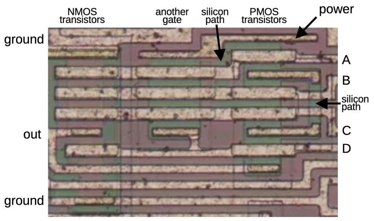
The diagram below shows this AND-NOR gate on the die, with the four inputs A, B, C, and D, corresponding to the schematic above. This gate has a few tricky layout features. The biggest surprise is that there is half of another gate (a 3-input NOR gate) in the middle of this gate. Presumably, the designers found this arrangement efficient since the other gate also uses inputs A, B, and C. The output of the other gate (D) is an input to the gate we're examining. Ignoring the other gate, the AND-NOR gate has the NMOS transistors in the first column, on top of a reddish band, and the PMOS transistors in the third column, on top of a greenish band. Hopefully you can recognize the transistor gates, the large rectangles connected to A, B, C, and D. Matching the schematic above, there are three NMOS transistors in series on the left, connected to A, B, and C, as well as the D transistor providing a second path between ground and the output. On the PMOS side, the A, B, and C transistors are in parallel, and then connected through the D transistor to the output. The green "silicon path" on the right provides the parallel connection from transistors A and B to transistors C and D. Most of this path is covered by two long metal regions, reducing the resistance. But in order to cross under wires B and C, the metal has a break where the green silicon provides the connection.

An AND-NOR gate on the die.

An AND-NOR gate on the die.

As with the other gates, the power is obtained by a connection to the bulk silicon, bridging the red and green regions. If you look closely, there is a green band ("silicon path") down from the power connection and joining the main green region between the B and C transistors, providing power to those transistors through the silicon. The NMOS transistors, on the other hand, have ground connections at the top and bottom. For this circuit, ground is supplied through solid metal wires at the top and the bottom, rather than a connection to the bulk silicon.

A few principles help when reverse-engineering logic gates. First, because of the complementary nature of CMOS, the output must either be pulled high by the PMOS transistors or pulled low by the NMOS transistors. Thus, one group or the other must be activated for each possible input. This implies that the same inputs must go to both the NMOS and PMOS transistors. Moreover, the structures of the NMOS and PMOS circuits are complementary: where the NMOS transistors are parallel, the PMOS transistors must be in series, and vice versa. In the case of the AND-NOR circuit above, these principles are helpful. For instance, you might not spot the "silicon paths", but since the PMOS half must be complementary to the NMOS half, you know that those connections must exist.

Even complex gates can be reverse-engineered by breaking the NMOS transistors into series and parallel groups, corresponding to AND and OR terms. Note that MOS transistors are inherently inverting, so a single gate will always end with inversion. Thus, you can build an AND-OR-AND-NOR gate for instance, but you can't build an AND gate as a single circuit.

Transmission gate

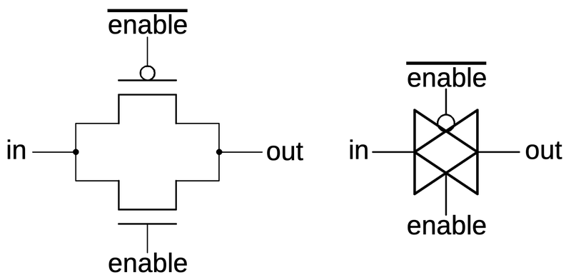
Another key circuit is the transmission gate. This acts as a switch, either passing a signal through or blocking it. The schematic below shows how a transmission gate is constructed from two transistors, an NMOS transistor and a PMOS transistor. If the enable line is high (i.e. low to the PMOS transistor) both transistors turn on, passing the input signal to the output. The NMOS transistor primarily passes a low signal, while the PMOS transistor passes a high signal, so they work together. If the enable line is low, both transistors turn off, blocking the input signal. The schematic symbol for a transmission gate is shown on the right. Note that the transmission gate is bidirectional; it doesn't have a specific input and output. Examining the surrounding circuitry usually reveals which side is the input and which side is the output.

A transmission gate is constructed from two transistors. The transistors and their gates are indicated. The schematic symbol is on the right.

A transmission gate is constructed from two transistors. The transistors and their gates are indicated. The schematic symbol is on the right.

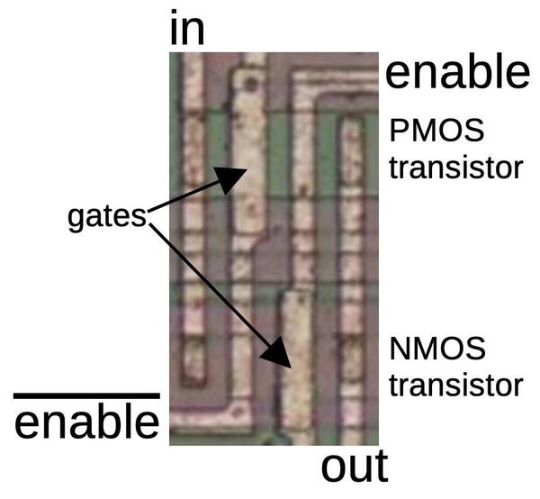
The photo below shows how a transmission gate appears on the die. It consists of a PMOS transistor at the top and an NMOS transistor at the bottom. Both the enable signal and the complemented enable signal are used, one for the NMOS transistor's gate and one for the PMOS transistor.

A transmission gate on the die, consisting of two transistors.

A transmission gate on the die, consisting of two transistors.

The inverter and transmission gate are both two-transistor circuits, but they can be easily distinguished for reverse engineering. One difference is that an inverter is connected to power and ground, while the transmission gate is unpowered. Moreover, the inverter has one input, while the transmission gate has three inputs (counting the control lines). In the inverter, both transistor gates have the same input, so one transistor turns on at a time. In the transmission gate, however, the gates have opposite inputs, so the transistors turn on or off together.

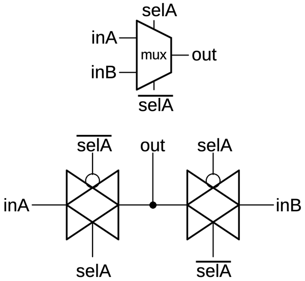
One useful circuit that can be built from transmission gates is the multiplexer, a circuit that selects one of two (or more) inputs. The multiplexer below selects either input inA or inB and connects it to the output, depending if the selection line selA is high or low respectively. The multiplexer can be built from two transmission gates as shown. Note that the select lines are flipped on the second transmission gate, so one transmission gate will be activated at a time. Multiplexers with more inputs can be built by using more transmission gates with additional select lines.

Schematic symbol for a multiplexer and its implementation with two transmission gates.

Schematic symbol for a multiplexer and its implementation with two transmission gates.

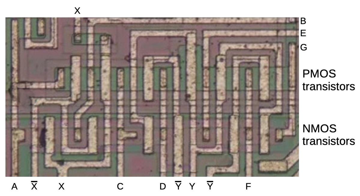
The die photo below shows a block of transmission gates consisting of six PMOS transistors and six NMOS transistors. The labels on the metal lines will make more sense as the reverse engineering progresses. Note that the metal layer provides much of the wiring for the circuit, but not all of it. Much of the wiring is implicit, in the sense that neighboring transistors are connected because the source of one transistor overlaps the drain of another.

A block of transistors implementing multiple transmission gates.

A block of transistors implementing multiple transmission gates.

While this may look like an incomprehensible block of zig-zagging lines, tracing out the transistors will reveal the circuitry (below). The wiring in the schematic matches the physical layout on the die, so the schematic is a bit of a mess. With a single layer of metal for wiring, the layout becomes a bit convoluted to avoid crossing wires. (The only wire crossing in this image is in the upper left for wire X; the signal uses a short stretch of silicon to pass under the metal.)

Schematic of the previous block of transistors.

Schematic of the previous block of transistors.

Looking at the PMOS and NMOS transistors as pairs reveals that the circuit above is a chain of transmission gates (shown below). It's not immediately obvious which wires are inputs and which wires are outputs, but it's a good guess that pairs of transmission gates using the opposite control lines form a multiplexer. That is, inputs A and C are multiplexed to output B, inputs C and E are multiplexed to output D, and so forth. As will be seen, these transmission gates form multiplexers that are part of a flip-flop.

The transistors form six transmission gates.

The transistors form six transmission gates.

Latches and flip-flops

Flip-flops and latches are important circuits, able to hold one bit and controlled by a clock signal. Terminology is inconsistent, but I'll use flip-flop to refer to an edge-triggered device and latch to refer to a level-triggered device. That is, a flip-flop will grab its input at the moment the clock signal goes high (i.e. it uses the clock edge), store it, and provide it as the output, called Q for historical reasons. A latch, on the other hand, will take its input, store it, and output it as long as the clock is high (i.e. it uses the clock level). The latch is considered "transparent", since the input immediately appears on the output if the clock is high.

The distinction between latches and flip-flops may seem pedantic, but it is important. Flip-flops will predictably update once per clock cycle, while latches will keep updating as long as the clock is high. By connecting the output of a flip-flop through an inverter back to the input, you can create a toggle flip-flop, which will flip its state once per clock cycle, dividing the clock by two. (This example will be important shortly.) If you try the same thing with a transparent latch, it will oscillate: as soon as the output flips, it will feed back to the latch input and flip again.

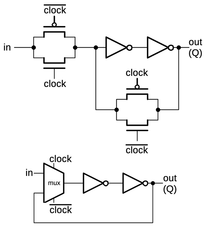
The schematic below shows how a latch can be implemented with transmission gates. When the clock is high, the first transmission gate passes the input through to the inverters and the output. When the clock is low, the second transmission gate creates a feedback loop for the inverters, so they hold their value, providing the latch action. Below, the same circuit is drawn with a multiplexer, which may be easier to understand: either the input or the feedback is selected for the inverters.

A latch implemented from transmission gates. Below, the same circuit is shown with a multiplexer.

A latch implemented from transmission gates. Below, the same circuit is shown with a multiplexer.

An edge-triggered flip-flop can be created by combining two latches in a primary/secondary arrangement. When the clock is low, the input will pass into the primary latch. When the clock switches high, two things happen. The primary latch will hold the current value of the input. Meanwhile, the secondary latch will start passing its input (the value from the primary latch) to its output, and thus the flip-flop output. The effect is that the flip-flop's output will be the value at the moment the clock goes high, and the flip-flop is insensitive to changes at other times. (The primary latch's value can keep changing while the clock is low, but this doesn't affect the flip-flop's output.)

Two latches, combined to form a flip-flop.

Two latches, combined to form a flip-flop.

The flip-flops in the counter chip are based on the above design, but they have two additional features. First, the flip-flop can be loaded with a value under the control of a Preset Enable (PE) signal. Second, the flip-flop can either hold its current value or toggle its value, under the control of a Toggle (T) signal. Implementing these features requires two more multiplexers in the primary latch as shown below. The first multiplexer selects either the inverted output or uninverted output to be fed back into the flip flop, providing the selectable toggle action. The second multiplexer is the latch's standard clocked multiplexer. The third multiplexer allows a "preset" value to be loaded directly into the flip-flop, bypassing the clock. (The preset value is inverted, since there are three inverters between the preset and the output.) The secondary latch is the same as before, except it provides the inverted and non-inverted outputs as feedback, allowing the flip-flop to either hold or toggle its value. This circuit illustrates how more complex flip-flops can be created from the building blocks that we've seen.

Schematic of the toggle flip-flop.

Schematic of the toggle flip-flop.

The gray letters in the schematic above match the earlier multiplexer diagram, showing how the three multiplexers were implemented on the die. The other multiplexer and the inverters are implemented in another block of circuitry. I won't explain that circuitry in detail since it doesn't illustrate any new principles.

Routing in silicon: cross-unders

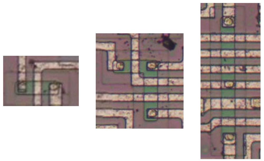
With just one metal layer for wiring, routing of signals on the chip is difficult and requires careful planning. Even so, there are some cases where one signal must cross another. This is accomplished by using silicon for a "cross-under", allowing a signal to pass underneath metal wiring. These cross-unders are avoided unless necessary because silicon has much higher resistance than metal. Moreover, the cross-under requires additional space on the die.

Three cross-unders on the die.

Three cross-unders on the die.

The images above show three cross-unders. In each one, signals are primarily routed in the metal layer, but a signal passes under the metal using a doped silicon region (which appears green). The first cross-under simply lets one signal cross under the second. The second image shows a signal branching as well as crossing under two signals. The third image shows a cross-under distributing a horizontal signal to the upper and lower halves of the chip, while crossing under multiple horizontal signals. Note the small oval contact between the green silicon region and the horizontal metal line, connecting them. It is easy to miss the small contact and think that the vertical signal is simply crossing under the horizontal signal, rather than branching.

About the chip

The focus of this article is the CMOS reverse engineering process rather than this specific chip, but I'll give a bit of information about the chip. The die has the Cyrillic characters ИЕ11 at the top indicating that the chip is a К561ИЕ11 or К564ИЕ11.12 The Soviet Union came up with a standardized numbering system for integrated circuits in 1968. This system is much more helpful than the American system of semi-random part numbers. In this part number, the 5 indicates a monolithic integrated circuit, while 61 or 64 is the series, specifically commercial-grade or military-grade clones of 4000 series CMOS logic. The character И indicates a digital circuit, while ИЕ is a counter. Thus, the part number systematically indicates that the integrated circuit is a CMOS counter.

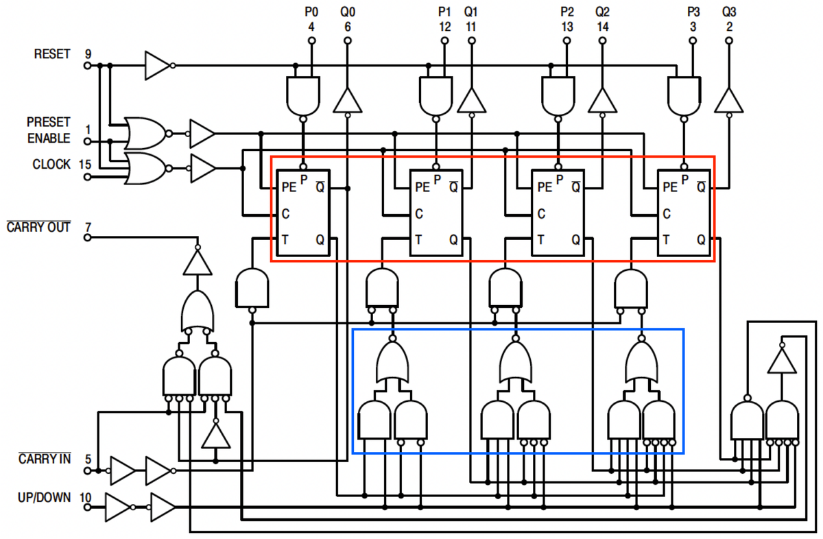
The 561ИЕ11 turns out to be a copy of the Motorola MC14516 binary up/down counter.13 Conveniently, the Motorola datasheet provides a schematic (below). I won't explain the schematic in detail, but a quick overview may be helpful. The chip is a four-bit counter that can count up or down, and the heart of the chip is the four toggle flip-flops (red). To count up, a flip-flop is toggled if there is a carry from the lower bits, while counting down toggles a flip-flop if there is a borrow from the lower bits. (Much like base-10 long addition or subtraction.) The AND/NOR gates at the bottom (blue) look complex, but they are just generating the toggle signal T: toggle if the lower bits are all-1's and you're counting up, or if the lower bits are all-0's and you're counting down. The flip-flops can also be loaded in parallel from the P inputs. Additional logic allows the chips to be cascaded to form arbitrarily large counters; the carry-out pin of one chip is connected to the carry-in of the next.

Logic diagram of the MC14516 up/down counter chip, from the datasheet.

Logic diagram of the MC14516 up/down counter chip, from the datasheet.

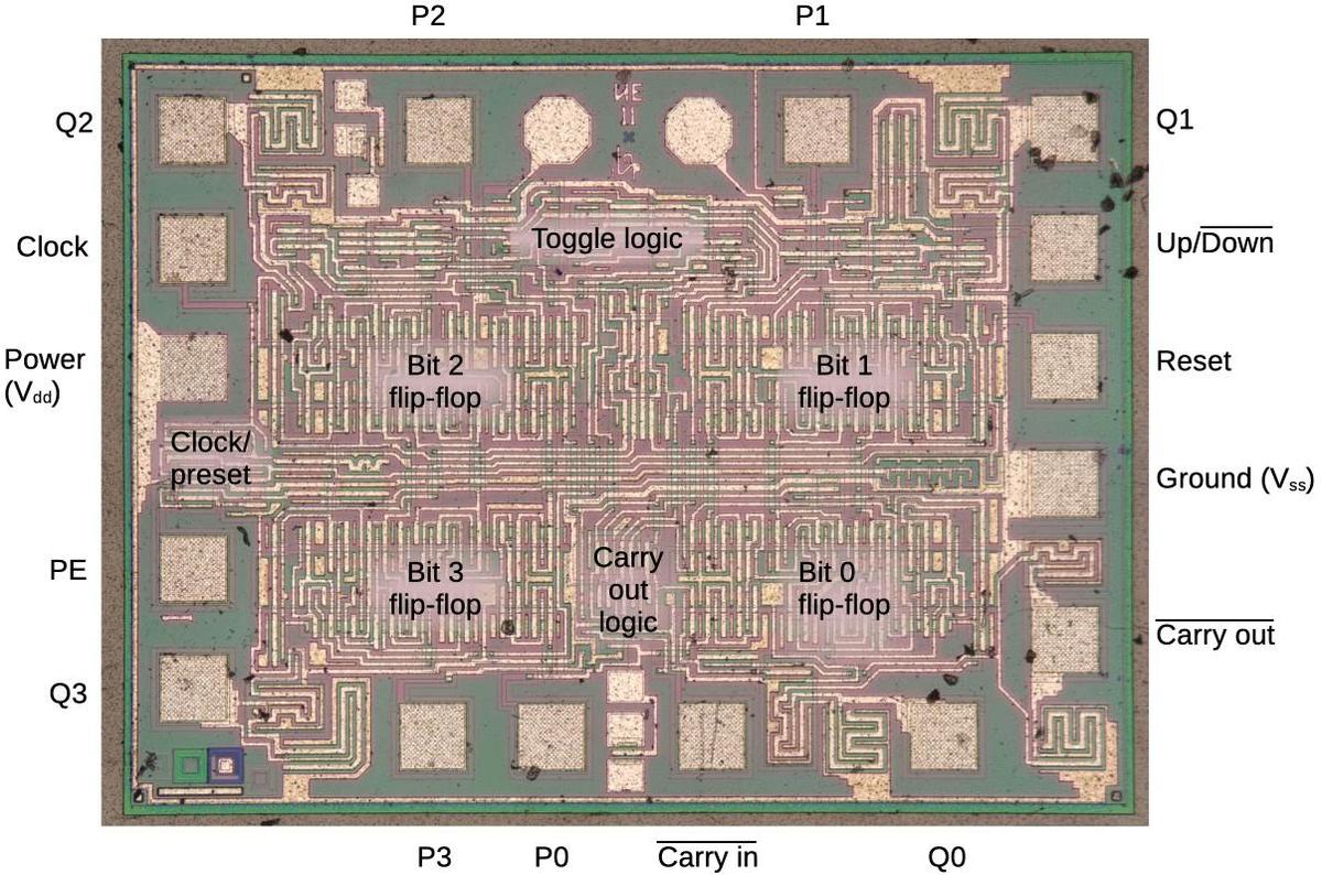
I've labeled the die photo below with the pin functions and the functional blocks. Each quadrant of the chip handles one bit of the counter in a roughly symmetrical way. This quadrant layout accounts for the pin arrangement which otherwise appears semi-random with bits 3 and 0 on one side and bits 2 and 1 on the other, with inputs and output pins jumbled together. The toggle and carry logic is squeezed into the top and middle of the chip. You may recognize the large inverters next to each output pin. When reverse-engineering, look for large transistors next to pads to determine which pins are outputs.

The die with pins and functional blocks labeled.

The die with pins and functional blocks labeled.

Conclusions

This article has discussed the basic circuits that can be found in a CMOS chip. Although the counter chip is old and simple, later chips use the same principles. An important change in later chips is the introduction of silicon-gate transistors, which use polysilicon for the transistor gates and for an additional wiring layer. The circuits are the same, but you need to be able to recognize the polysilicon layer. Many chips have more than one metal layer, which makes it very hard to figure out the wiring connections. Finally, when the feature size approaches the wavelength of light, optical microscopes break down. Thus, these reverse-engineering techniques are only practical up to a point. Nonetheless, many interesting CMOS chips can be studied and reverse-engineered.

For more, follow me on Twitter @kenshirriff or RSS for updates. I'm also on Mastodon as @[email protected]. Thanks to Martin Evtimov for providing the die photos.

Notes and references

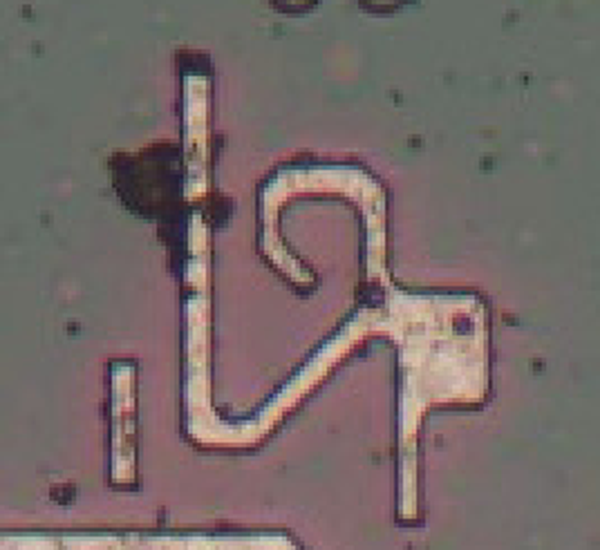
  1. I'm not sure of the date and manufacturing location of the chip. I think the design is old, from the Soviet Union. (Motorola introduced the MC14516 around 1972 but I don't know when it was copied.) The wafer is said to be scrap from a Ukrainian manufacturer so it may have been manufactured more recently. The die has a symbol that might be a manufacturing logo, but nobody on Twitter could identify it.

    A symbol that appears on the die.

    A symbol that appears on the die.


  2. For more about this chip, the Russian databook can be downloaded here; see Volume 5 page 501. 

  3. Early CMOS microprocessors include the 8-bit RCA 1802 COSMAC (1974) and the 12-bit Intersil 6100 (1974). The 1802 is said to be the first CMOS microprocessor. Mainstream microprocessors didn't switch to CMOS until the mid-1980s. 

  4. The chip in this article has metal-gate transistors, with aluminum forming the transistor gate. These transistors were not as advanced as the silicon-gate transistors that were developed in the late 1960s. Silicon gate technology was much better in several ways. First, silicon-gate transistors were smaller, faster, more reliable, and used lower voltages. Second, silicon-gate chips have a layer of polysilicon wiring in addition to the metal wiring; this made chip layouts about twice as dense. 

  5. To produce N-type silicon, the silicon is doped with small amounts of an element such as phosphorus or arsenic. In the periodic table, these elements are one column to the right of silicon so they have one "extra" electron. The free electrons move through the silicon, carrying charge. Because electrons are negative, this type of silicon is called N-type. Conversely, to produce P-type silicon, the silicon is doped with small quantities of an element such as boron. Since boron is one column to the left of silicon in the periodic table, it has one fewer free electrons. A strange thing about semiconductor physics is that the missing electrons (called holes) can move around the silicon much like electrons, but carrying positive charge. Since the charge carriers are positive, this type of silicon is called P-type. For various reasons, electrons carry charge better than holes, so NMOS transistors work better than PMOS transistors. As a result, PMOS transistors need to be about twice the size of comparable NMOS transistors. This quirk is useful for reverse engineering, since it can help distinguish NMOS and PMOS transistors.

    The amount of doping required can be absurdly small, 20 atoms of boron for every billion atoms of silicon in some cases. A typical doping level for N-type silicon is 1015 atoms of phosphorus or arsenic per cubic centimeter, which sounds like a lot until you realize that pure silicon consists of 5×10²² atoms per cubic centimeter. A heavily doped P+ region might have 1020 dopant atoms per cubic centimeter, one atom of boron per 500 atoms of silicon. (Doping levels are described here.) 

  6. This chip is built on a substrate of N-type silicon, with wells of P-type silicon for the NMOS transistors. Chips can be built the other way around, starting with P-type silicon and putting wells of N-type silicon for the PMOS transistors. Another approach is the "twin-well" CMOS process, constructing wells for both NMOS and PMOS transistors. 

  7. The bulk silicon voltage makes the boundary between a transistor and the bulk silicon act as a reverse-biased diode, so current can't flow across the boundary. Specifically, for a PMOS transistor, the N-silicon substrate is connected to the positive supply. For an NMOS transistor, the P-silicon well is connected to ground. A P-N junction acts as a diode, with current flowing from P to N. But the substrate voltages put P at ground and N at +5, blocking any current flow. The result is that the bulk silicon can be considered an insulator, with current restricted to the N+ and P+ doped regions. If this back bias gets reversed, for example, due to power supply fluctuations, current can flow through the substrate. This can result in "latch-up", a situation where the N and P regions act as parasitic NPN and PNP transistors that latch into the "on" state. This shorts power and ground and can destroy the chip. The point is that the substrate voltages are very important for proper operation of the chip. 

  8. Many inverters in this chip duplicate the transistors to increase the current output. The same effect could be achieved with single transistors with twice the gate width. (That is, twice the height in the diagrams.) Because these transistors are arranged in uniform rows, doubling the transistor height would mess up the layout, so using more transistors instead of changing the size makes sense. 

  9. Some chips use dynamic logic, in which case it is okay to leave the gate floating, neither pulled high nor low. Since the gate resistance is extremely high, the capacitance of a gate will hold its value (0 or 1) for a short time. After a few milliseconds, the charge will leak away, so dynamic logic must constantly refresh its signals before they decay.

    In general, the reason you don't want an intermediate voltage as the input to a CMOS circuit is that the voltage might end up turning the PMOS transistor partially on while also turning the NMOS transistor partially on. The result is high current flow from power to ground through the transistors. 

  10. One of the complicated logic gates on the die didn't match the implementation I expected. In particular, for some inputs, the output is neither pulled high nor low. Tracing the source of these inputs reveals what is going on: the gate takes both a signal and its complement as inputs. Thus, some of the "theoretical" inputs are not possible; these can't be both high or both low. The logic gate is optimized to ignore these cases, making the implementation simpler. 

  11. This schematic explains the physical layout of the 3-input NOR gate on the die, in case the wiring isn't clear. Note that the PMOS transistors are wired in series and the NMOS transistors are in parallel, even though both types are physically arranged in rows.

    The 3-input NOR gate on the die. This schematic matches the physical layout.

    The 3-input NOR gate on the die. This schematic matches the physical layout.


  12. The commercial-grade chips and military-grade chips presumably use the same die, but are distinguished by the level of testing. So we can't categorize the die as 561-series or 564-series. 

  13. Motorola introduced the MC14500 series in 1971 to fill holes in the CD4000 series. For more about this series, see A Strong Commitment to Complementary MOS

Inside the mechanical Bendix Air Data Computer, part 3: pressure transducers

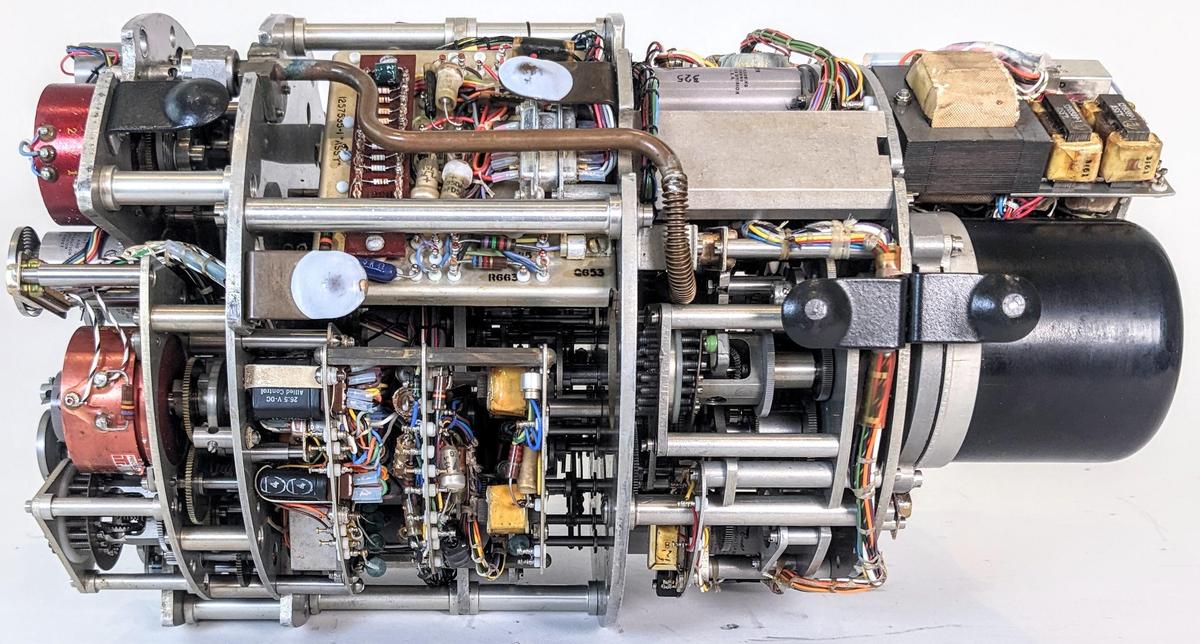
The Bendix Central Air Data Computer (CADC) is an electromechanical analog computer that uses gears and cams for its mathematics. It was a key part of military planes such as the F-101 and the F-111 fighters, computing airspeed, Mach number, and other "air data". This article reverse-engineers the two pressure transducers, on the right in the photo below. It is part 3 of my series on the CADC.1

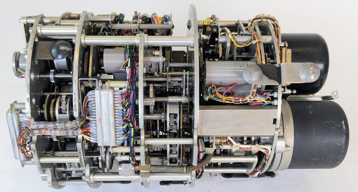
The Bendix MG-1A Central Air Data Computer with the case removed, showing the compact gear mechanisms inside. Click this image (or any other) for a larger version.

The Bendix MG-1A Central Air Data Computer with the case removed, showing the compact gear mechanisms inside. Click this image (or any other) for a larger version.

Aircraft have determined airspeed from air pressure for over a century. A port in the side of the plane provides the static air pressure,2 the air pressure outside the aircraft. A pitot tube points forward and receives the "total" air pressure, a higher pressure due to the speed of the airplane forcing air into the tube. The airspeed can be determined from the ratio of these two pressures, while the altitude can be determined from the static pressure.

But as you approach the speed of sound, the fluid dynamics of air change and the calculations become very complicated. With the development of supersonic fighter planes in the 1950s, simple mechanical instruments were no longer sufficient. Instead, an analog computer calculated the "air data" (airspeed, air density, Mach number, and so forth) from the pressure measurements. This computer then transmitted the air data electrically to the systems that needed it: instruments, weapons targeting, engine control, and so forth. Since the computer was centralized, such a system was called a Central Air Data Computer or CADC, manufactured by Bendix and other companies.

A closeup of the numerous gears inside the CADC. Three differential gear mechanisms are visible.

A closeup of the numerous gears inside the CADC. Three differential gear mechanisms are visible.

Each value in the Bendix CADC is indicated by the rotational position of a shaft. Compact electric motors rotated the shafts, controlled by magnetic amplifier servo loops. Gears, cams, and differentials performed computations, with the results indicated by more rotations. Devices called synchros converted the rotations to electrical outputs that controlled other aircraft systems. The CADC is said to contain 46 synchros, 511 gears, 820 ball bearings, and a total of 2,781 major parts (but I haven't counted). These components are crammed into a compact cylinder: 15 inches long and weighing 28.7 pounds.

The equations computed by the CADC are impressively complicated. For instance, one equation computes the Mach number $M$ from the total pressure \( P_t \) and the static pressure \( P_s \):3

\[~~~\frac{P_t}{P_s} = \frac{166.9215M^7}{( 7M^2-1)^{2.5}}\]

It seems incredible that these functions could be computed mechanically, but three techniques make this possible. The fundamental mechanism is the differential gear, which adds or subtracts values. Second, logarithms are used extensively, so multiplications and divisions become additions and subtractions performed by a differential, while square roots are calculated by gearing down by a factor of 2. Finally, specially-shaped cams implement functions: logarithm, exponential, and other one-variable functions.4 By combining these mechanisms, complicated functions can be computed mechanically.

The pressure transducers

In this article, I'm focusing on the pressure transducers and how they turn pressures into shaft rotations. The CADC receives two pressure inputs: the total pressure \( P_t \) from the pitot tube, and the static pressure \( P_s \) from the static pressure port.5 The CADC has two independent pressure transducer subsystems, one for total pressure and one for static pressure. The two pressure transducers make up the right half of the CADC. The copper pressure tube for the static pressure is visible on top of the CADC below. This tube feeds into the black-domed pressure sensor at the right. The gears, motors, and other mechanisms to the left of the pressure sensor domes generate shaft rotations that are fed into the remainder of the CADC for calculations.

Side view of the CADC.

Side view of the CADC.

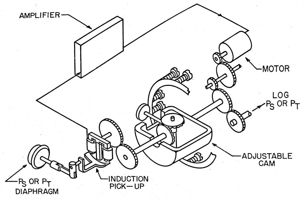
The pressure transducer has a tricky job: it must measure tiny pressure changes, but it must also provide a rotational signal that has enough torque to rotate all the gears in the CADC. To accomplish this, the pressure transducer uses a servo loop that amplifies small pressure changes into accurate rotations. The diagram below provides an overview of the process. The pressure input causes a small movement in the bellows diaphragm. This produces a small shaft rotation that is detected by a sensitive inductive pickup. This signal is amplified and drives a motor with enough power to drive the output shaft. The motor is also geared to counteract the movement of the bellows. The result is a feedback loop so the motor's rotation tracks the air pressure, but provides much more torque. An adjustable cam corrects for any error produced by irregularities in the diaphragm response. This complete mechanism is implemented twice, once for each pressure input.

This diagram shows the structure of the transducer. From "Air Data Computer Mechanization."

This diagram shows the structure of the transducer. From "Air Data Computer Mechanization."

To summarize, as the pressure moves the diaphragm, the induction pick-up produces an error signal. The motor is driven in the appropriate direction until the error signal becomes zero. At this point, the output shaft rotation exactly matches the input pressure. The advantage of the servo loop is that the diaphragm only needs to move the sensitive inductive pickup, rather than driving the gears of the CADC, so the pressure reading is more accurate.

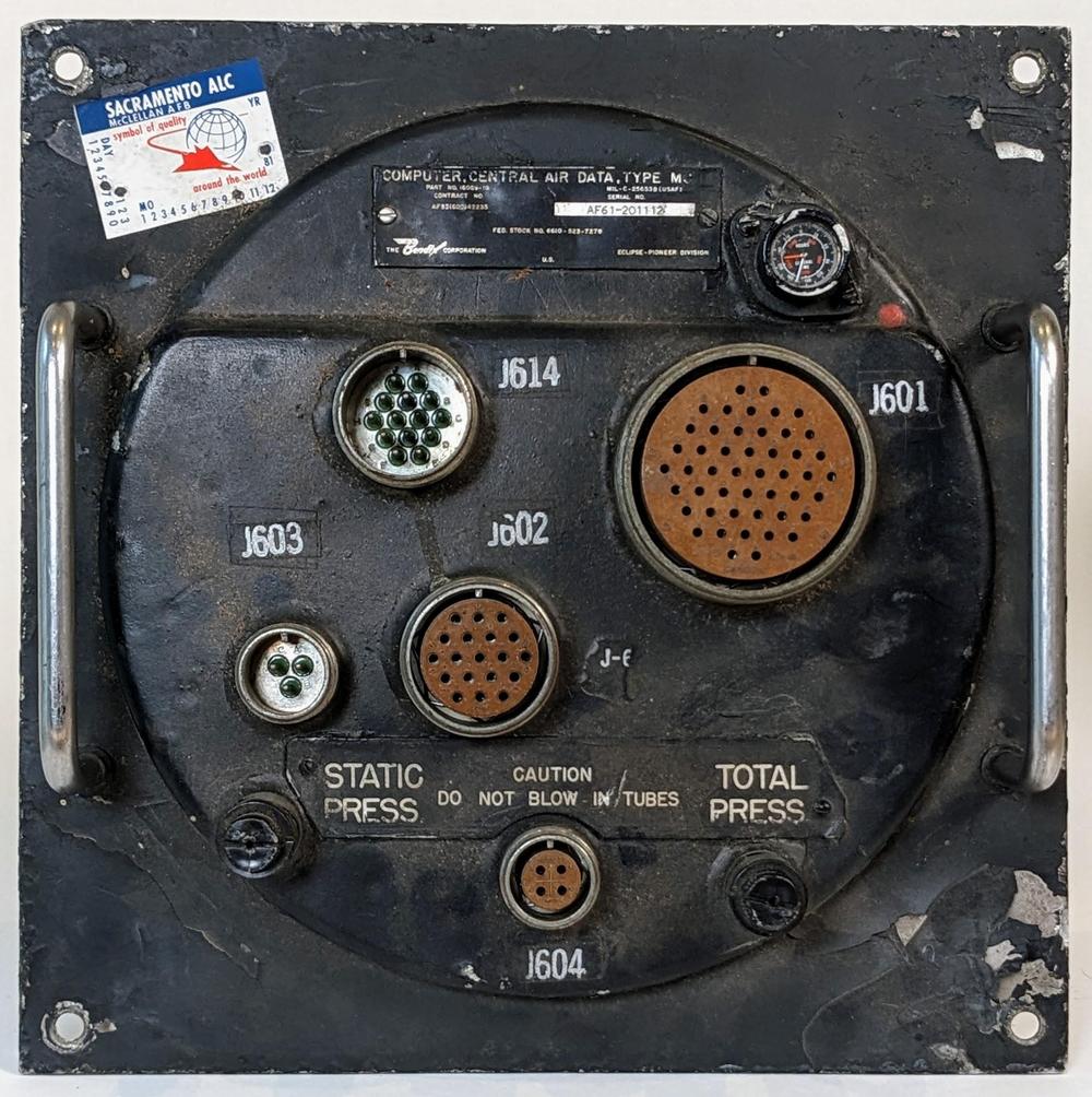
In more detail, the process starts with connections from the aircraft's pitot tube and static pressure port to the CADC. The front of the CADC (below) has connections for the total pressure and the static pressure. The CADC also has five round military connectors for electrical connections between the CADC and the rest of the aircraft. (The outputs from the CADC are electrical, with synchros converting the shaft rotations into electrical representations.) Finally, a tiny time clock at the upper right keeps track of how many hours the CADC has been in operation, so it can be maintained according to schedule.

The front panel of the CADC, showing the static pressure and total pressure connections at the bottom.

The front panel of the CADC, showing the static pressure and total pressure connections at the bottom.

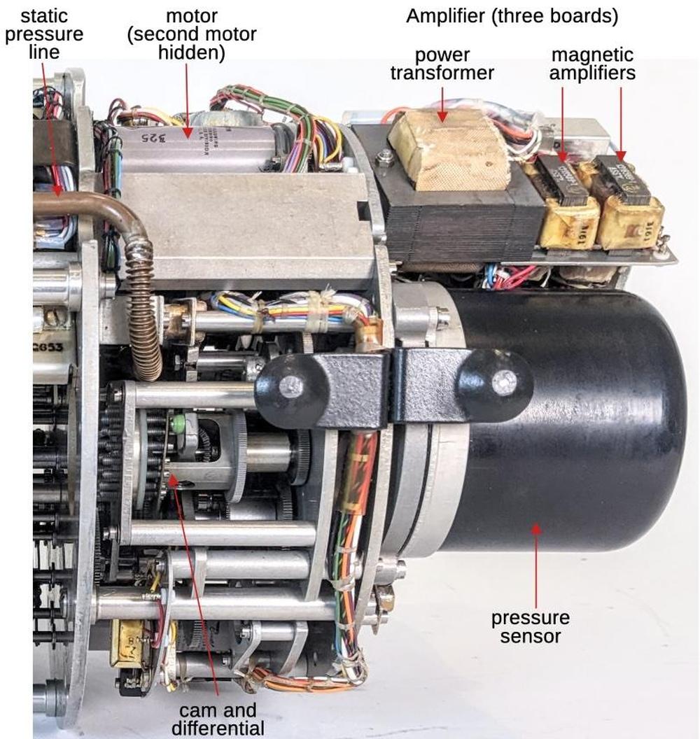
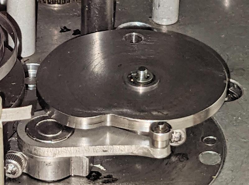
The photo below shows the main components of the pressure transducer system. At the upper left, the pressure line from the CADC's front panel goes to the pressure sensor, airtight under a black dome. The error signal from the sensor goes to the amplifier, which consists of three boards. The amplifier's power transformer and magnetic amplifiers are the most visible components. The amplifier drives the motors to the left. There are two motors controlled by the amplifier: one for coarse adjustments and one for fine adjustments. By using two motors, the CADC can respond rapidly to large pressure changes, while also accurately tracking small pressure changes. Finally, the output from the motor goes through the adjustable cam in the middle before providing the feedback signal to the pressure sensor. The output from the transducer to the rest of the CADC is a shaft on the left, but it is in the middle of the CADC and isn't visible in the photo.

A closeup of the transducer, showing the main parts.

A closeup of the transducer, showing the main parts.

The pressure sensor

Each pressure sensor is packaged in a black airtight dome and is fed from its associated pressure line. Inside the sensor, two sealed metal bellows (below) expand or contract as the pressure changes. The bellows are connected to opposite sides of a metal shaft, which rotates as the bellows expand or contract. This shaft rotates an inductive pickup, providing the error signal. The servo loop rotates a second shaft that counteracts the rotation of the first shaft; this shaft and gears are also visible below.

Inside the pressure transducer. The two disc-shaped bellows are connected to opposite sides of a shaft so the shaft rotates as the bellows expand or contract.

Inside the pressure transducer. The two disc-shaped bellows are connected to opposite sides of a shaft so the shaft rotates as the bellows expand or contract.

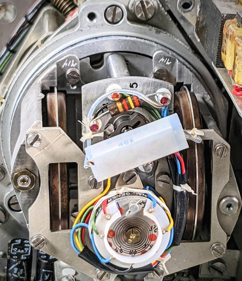
The end view of the sensor below shows the inductive pickup at the bottom, with colorful wires for the input (400 Hz AC) and the output error signal. The coil visible on the inductive pickup is an anti-backlash spring to ensure that the pickup doesn't wobble back and forth. The electrical pickup coil is inside the inductive pickup and isn't visible.

Inside the transducer housing, showing the bellows and inductive pickup.

Inside the transducer housing, showing the bellows and inductive pickup.

The amplifier

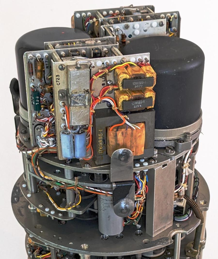
Each transducer feedback signal is amplified by three circuit boards centered around magnetic amplifiers, transformer-like amplifiers that were popular before high-power transistors came along. The photo below shows how the amplifier boards are packed next to the transducers. The boards are complex, filled with resistors, capacitors, germanium transistors, diodes, relays, and other components.

The pressure transducers are the two black domes at the top. The circuit boards next to each pressure transducer are the amplifiers. The yellowish transformer-like devices with three windings are the magnetic amplifiers.

The pressure transducers are the two black domes at the top. The circuit boards next to each pressure transducer are the amplifiers. The yellowish transformer-like devices with three windings are the magnetic amplifiers.

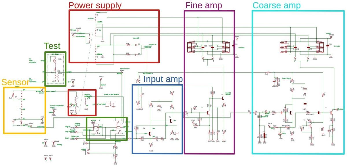
I reverse-engineered the boards and created the schematic below. I'll discuss the schematic at a high level; click it for a larger version if you want to see the full circuitry. The process starts with the inductive sensor (yellow), which provides the error input signal to the amplifier. The first stage of the amplifier (blue) is a two-transistor amplifier and filter. From there, the signal goes to two separate output amplifiers to drive the two motors: fine (purple) and coarse (cyan).

Schematic of the servo amplifier, probably with a few errors. Click for a larger version.

Schematic of the servo amplifier, probably with a few errors. Click for a larger version.

The inductive sensor provides its error signal as a 400 Hz sine wave, with a larger signal indicating more error. The phase of the signal is 0° or 180°, depending on the direction of the error. In other words, the error signal is proportional to the driving AC signal in one direction and flipped when the error is in the other direction. This is important since it indicates which direction the motors should turn. When the error is eliminated, the signal is zero.

Each output amplifier consists of a transistor circuit driving two magnetic amplifiers. Magnetic amplifiers are an old technology that can amplify AC signals, allowing the relatively weak transistor output to control a larger AC output. The basic idea of a magnetic amplifier is a controllable inductor. Normally, the inductor blocks alternating current. But applying a relatively small DC signal to a control winding causes the inductor to saturate, permitting the flow of AC. Since the magnetic amplifier uses a small signal to control a much larger signal, it provides amplification.

In the early 1900s, magnetic amplifiers were used in applications such as dimming lights. Germany improved the technology in World War II, using magnetic amplifiers in ships, rockets, and trains. The magnetic amplifier had a resurgence in the 1950s; the Univac Solid State computer used magnetic amplifiers (rather than vacuum tubes or transistors) as its logic elements. However, improvements in transistors made the magnetic amplifier obsolete except for specialized applications. (See my IEEE Spectrum article on magnetic amplifiers for more history of magnetic amplifiers.)

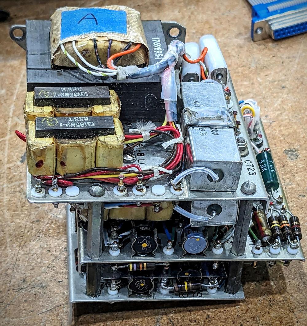
In the CADC, magnetic amplifiers control the AC power to the motors. Two magnetic amplifiers are visible on top of the amplifier board stack, while two more are on the underside; they are the yellow devices that look like transformers. (Behind the magnetic amplifiers, the power transformer is labeled "A".)

One of the three-board amplifiers for the pressure transducer.

One of the three-board amplifiers for the pressure transducer.

The transistor circuit generates the control signal to the magnetic amplifiers, and the output of the magnetic amplifiers is the AC signal to the motors. Specifically, the CADC uses two magnetic amplifiers for each motor. One magnetic amplifier powers the motor to spin clockwise, while the other makes the motor spin counterclockwise. The transistor circuit will pull one magnetic amplifier winding low; the phase of the input signal controls which magnetic amplifier, and thus the motor direction. (If the error input signal is zero, neither winding is pulled low, both magnetic amplifiers block AC, and the motor doesn't turn.)6 The result of this is that the motor will spin in the correct direction based on the error input signal, rotating the mechanism until the mechanical output position matches the input pressure. The motors are "Motor / Tachometer Generator" units that also generate a voltage based on their speed. This speed signal is fed into the transistor amplifier to provide negative feedback, limiting the motor speed as the error becomes smaller and ensuring that the feedback loop doesn't overshoot.

The other servo loops in the CADC (temperature and position error correction) have one motor driver constructed from transistors and two magnetic amplifiers. However, each pressure transducer has two motor drivers (and thus four magnetic amplifiers), one for fine adjustment and one for coarse adjustment. This allows the servo loop to track the input pressure very closely, while also adjusting rapidly to larger changes in pressure. The coarse amplifier uses back-to-back diodes to block small changes; only input voltages larger than a diode drop will pass through and energize the coarse amplifier.

The CADC is powered by standard avionics power of 115 volts AC, 400 hertz. Each pressure transducer amplifier has a simple power supply running off this AC, using a multi-winding power transformer. A center-tapped winding and full wave rectifier produces DC for the transistor amplifiers. Other windings supply AC (controlled by the magnetic amplifiers) to power the motors, AC for the magnetic amplifier control signals, and AC for the sensor. The transformer ensures that the transducer circuitry is electrically isolated from other parts of the CADC and the aircraft. The power supply is indicated in red in the schematic above.

The schematic also shows test circuitry (blue). One of the features of the CADC is that it can be set to two test configurations before flight to ensure that the system is operating properly and is correctly calibrated.7 Two relays allow the pressure transducer to switch to one of two test inputs. This allows the CADC to be checked for proper operation and calibration. The test inputs are provided from an external board and a helical feedback potentiometer (Helipot) that provides simulated sensor input.

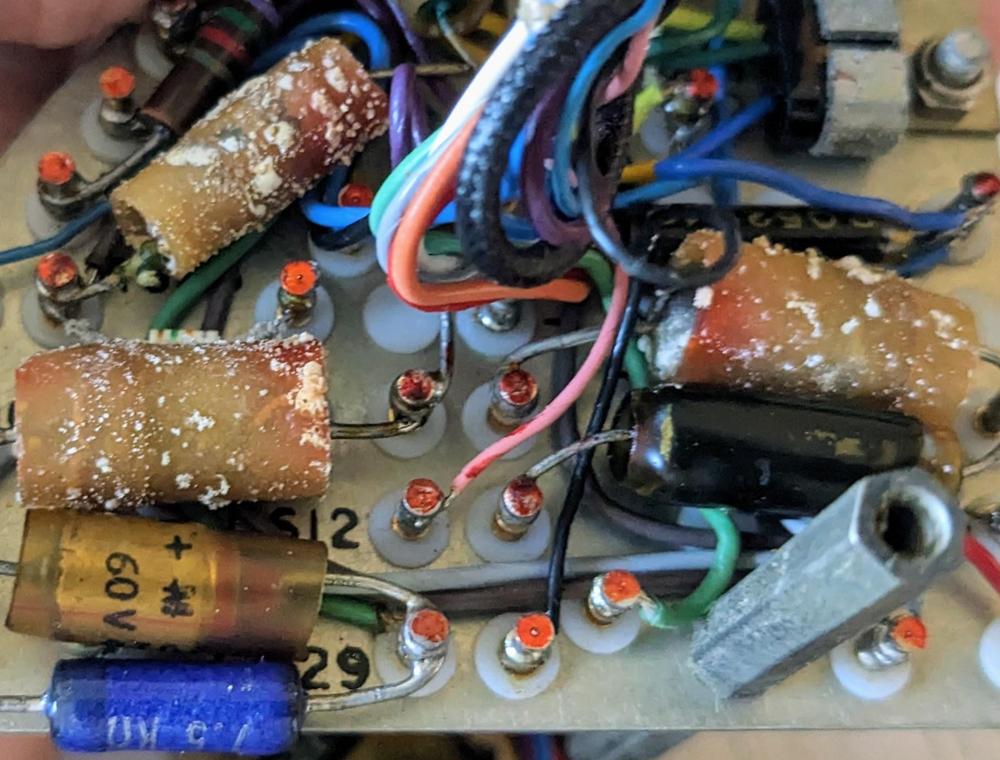
Getting the amplifiers to work was a challenge. Many of the capacitors in the CADC had deteriorated and failed, as shown below. Marc went through the CADC boards and replaced the bad capacitors. However, one of the pressure transducer boards still failed to work. After much debugging, we discovered that one of the new capacitors had also failed. Finally, after replacing that capacitor a second time, the CADC was operational.

Some bad capacitors in the CADC. This is the servo amplifier for the temperature sensor.

Some bad capacitors in the CADC. This is the servo amplifier for the temperature sensor.

The mechanical feedback loop

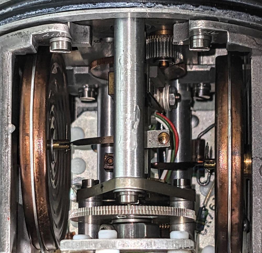
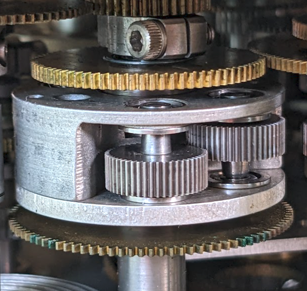
The amplifier boards energize two motors that rotate the output shaft,8 the coarse and fine motors. The outputs from the coarse and fine motors are combined through a differential gear assembly that sums its two input rotations.9 While the differential functions like the differential in a car, it is constructed differently, with a spur-gear design. This compact arrangement of gears is about 1 cm thick and 3 cm in diameter. The differential is mounted on a shaft along with three co-axial gears: two gears provide the inputs to the differential and the third provides the output. In the photo, the gears above and below the differential are the input gears. The entire differential body rotates with the sum, connected to the output gear at the top through a concentric shaft. The two thick gears inside the differential body are part of its mechanism.

A closeup of a differential mechanism.

A closeup of a differential mechanism.

(Differential gear assemblies are also used as the mathematical component of the CADC, as it performs addition or subtraction. Since most values in the CADC are expressed logarithmically, the differential computes multiplication and division when it adds or subtracts its inputs.)

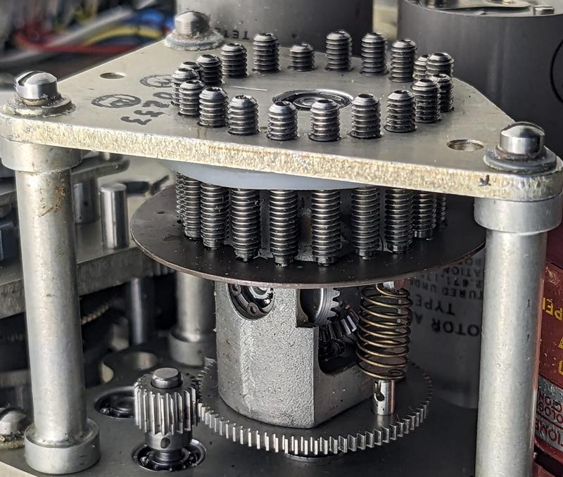
The CADC uses cams to correct for nonlinearities in the pressure sensors. The cam consists of a warped metal plate. As the gear rotates, a spring-loaded vertical follower moves according to the shape of the plate. The differential gear assembly under the plate adds this value to the original input to obtain a corrected value. (This differential implementation is different from the one described above.) The output from the cam is fed into the pressure sensor, closing the feedback loop.

The corrector cam is adjusted to calibrate the output to counteract for variations in the bellows behavior.

The corrector cam is adjusted to calibrate the output to counteract for variations in the bellows behavior.

At the top, 20 screws can be rotated to adjust the shape of the cam plate and thus the correction factor. These cams allow the CADC to be fine-tuned to maximize accuracy. According to the spec, the required accuracy for pressure was "40 feet or 0.15 percent of attained altitude, whichever is greater."

Conclusions

The Bendix CADC was built at an interesting point in time, when computations could be done digitally or analog, mechanically or electrically. Because the inputs were analog and the desired outputs were analog, the decision was made to use an analog computer for the CADC. Moreover, transistors were available but their performance was limited. Thus, the servo amplifiers are built from a combination of transistors and magnetic amplifiers.

Modern air data computers are digital but they are still larger than you might expect because they need to handle physical pressure inputs. While a drone can use a tiny 5mm MEMS pressure sensor, air data computers for aircraft have higher requirements and typically use larger vibrating cylinder pressure sensors. Even so, at 45 mm long, the modern pressure sensor is dramatically smaller than the CADC's pressure transducer with its metal-domed bellows sensor, three-board amplifier, motors, cam, and gear train. Although the mechanical Bendix CADC seems primitive, this CADC was used by the Air Force until the 1980s. I guess if the system worked, there was no reason to update it.

I plan to continue reverse-engineering the Bendix CADC,10 so follow me on Twitter @kenshirriff or RSS for updates. I'm also on Mastodon as @oldbytes.space@kenshirriff. Thanks to Joe for providing the CADC. Thanks to Nancy Chen for obtaining a hard-to-find document for me. Marc Verdiell and Eric Schlaepfer are working on the CADC with me.

Notes and references

  1. My previous posts on the CADC provide an overview and reverse-engineering of the left side. Much of the background of this article is copied from the previous articles, if it looks familiar. 

  2. The static air pressure can also be provided by holes in the side of the pitot tube. I couldn't find information indicating exactly how the planes with the CADC received static pressure. 

  3. Although the CADC's equations may seem ad hoc, they can be derived from fluid dynamics principles. These equations were standardized in the 1950s by various government organizations including the National Bureau of Standards and NACA (the precursor of NASA). 

  4. The CADC also uses cams to implement functions such as logarithms, exponentials, and complicated functions of one variable such as ${M}/{\sqrt{1 + .2 M^2}}$. These cams have a completely different design from the corrector cams. The function cams are fixed shape, unlike the adjustable corrector cams. The function is encoded into the cam's shape during manufacturing, so implementing a hard-to-compute nonlinear function isn't a problem for the CADC. The photo below shows a cam with the follower arm in front. As the cam rotates, the follower moves in and out according to the cam's radius. The pressure transducers do not use fixed cams, so I won't discuss them more in this article.

    A cam inside the CADC implements a function.

    A cam inside the CADC implements a function.


  5. The CADC also has an input for the "position error correction". This input provides a correction factor because the measured static pressure may not exactly match the real static pressure. The problem is that the static pressure is measured from a port on the aircraft. Distortions in the airflow may cause errors in this measurement. A separate box, the "compensator", determined the correction factor based on the angle of attack and fed it to the CADC as a synchro signal. The position error correction is applied in a separate section of the CADC, downstream from the transducers, so I will ignore it for this article. 

  6. A bit more explanation of the transistor circuit driving the magnetic amplifier. The idea is that one magnetic amplifier or the other is selected, depending on the phase of the error signal, causing the motor to turn counterclockwise or clockwise as needed. To implement this, the magnetic amplifier control windings are connected to opposite phases of the 400 Hz power. The transistor is connected to both magnetic amplifiers through diodes, so current will flow only if the transistor pulls the winding low during the half-cycle that the winding is powered high. Thus, depending on the phase of the transistor output, one winding or the other will be powered, allowing that magnetic amplifier to pass AC to the motor. 

  7. According to the specification, the CADC has simulated "low point" and "high point" test conditions. The low point is 11,806 feet altitude, 1064 ft/sec true airspeed, Mach .994, total temperature 317.1 °K, and density × speed of sound of 1.774 lb sec/ft3. The high point is 50,740 feet altitude, 1917 ft/sec true airspeed, Mach 1.980, total temperature 366.6 °K, and density × speed of sound of .338 lb sec/ft3

  8. The motor part number is Bendix FV101-5A1. 

  9. Strictly speaking, the output of the differential is the sum of the inputs divided by two. I'm ignoring the factor of 2 because the gear ratios can easily cancel it out. It's also arbitrary whether you think of the differential as adding or subtracting, since it depends on which rotation direction is defined as positive. 

  10. It was very difficult to find information about the CADC. The official military specification is MIL-C-25653C(USAF). After searching everywhere, I was finally able to get a copy from the Technical Reports & Standards unit of the Library of Congress. The other useful document was in an obscure conference proceedings from 1958: "Air Data Computer Mechanization" (Hazen), Symposium on the USAF Flight Control Data Integration Program, Wright Air Dev Center US Air Force, Feb 3-4, 1958, pp 171-194. 

Interesting double-poly latches inside AMD's vintage LANCE Ethernet chip

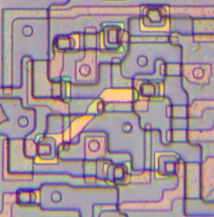
I've studied a lot of chips from the 1970s and 1980s, so I usually know what to expect. But an Ethernet chip from 1982 had something new: a strange layer of yellow wiring on the die. After some study, I learned that the yellow wiring is a second layer of resistive polysilicon, used in the chip's static storage cells and latches.

A closeup of the die of the LANCE chip. The metal has been removed to show the layers underneath.

A closeup of the die of the LANCE chip. The metal has been removed to show the layers underneath.

The die photo above shows a closeup of a latch circuit, with the diagonal yellow stripe in the middle. For this photo, I removed the chip's metal layer so you can see the underlying circuitry. The bottom layer, silicon, appears gray-purple under the microscope, with the active silicon regions slightly darker and bordered in black. On top of the silicon, the pink regions are polysilicon, a special type of silicon. Polysilicon has a critical role in the chip: when it crosses active silicon, polysilicon forms the gate of a transistor. The circles are contacts between the metal layer and the underlying silicon or polysilicon. So far, the components of the chip match most NMOS chips of that time. But what about the bright yellow line crossing the circuit diagonally? That was new to me. This second layer of polysilicon provides resistance. It crosses over the other layers, connected to the silicon at the ends with a complex ring structure.

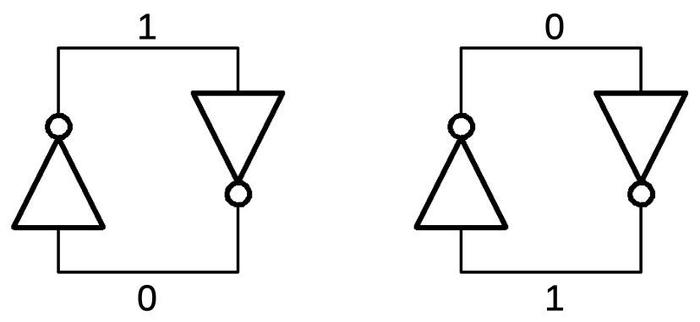
Why would you want high-resistance wiring in your digital chip? To understand this, let's first look at how a bit can be stored. An efficient way to store a bit is to connect two inverters in a loop, as shown below. Each inverter sends the opposite value to the other inverter, so the circuit will be stable in two states, holding one bit: a 1 or a 0.

Two cross-coupled inverters can store either a 0 or a 1 bit.

Two cross-coupled inverters can store either a 0 or a 1 bit.

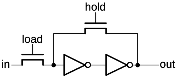
But how do you store a new value into the inverter loop? There are a few techniques. One is to use pass transistors to break the loop, allowing a new value to be stored. In the schematic below, if the hold signal is activated, the transistor turns on, completing the loop. But if hold is dropped and load is activated, a new value can be loaded from the input into the inverter loop.

A latch, controlled by pass transistors.

A latch, controlled by pass transistors.

An alternative is to use a weak inverter that produces a low-current output. In this case, the input signal can simply overpower the value produced by the inverter, forcing the loop into a new state. The advantage of this circuit is that it eliminates the "hold" transistor. However, a weak inverter turns out to be larger than a regular inverter, negating much of the space saving.1 (The Intel 386 processor uses this type of latch.)

A latch using a weak inverter.

A latch using a weak inverter.

A third alternative, used in the Ethernet chip, is to use a resistor for the feedback, limiting the current.2 As in the previous circuit, the input can overpower the low feedback current. However, this circuit is more compact since it doesn't require a larger inverter. The resistor doesn't require additional space since it can overlap the rest of the circuitry, as shown in the photo at the top of the article. The disadvantage is that manufacturing the die requires additional processing steps to create the resistive polysilicon layer.

A latch using a resistor for feedback.

A latch using a resistor for feedback.

In the Ethernet chip, this type of latch is used in many circuits. For example, shift registers are built by connecting latches in sequence, controlled by the clock signals. Latches are also used to create binary counters, with the latch value toggled when the lower bits produce a carry.

The SRAM cell

It would be overkill to create a separate polysilicon layer just for a few latches. It turns out that the chip was constructed with AMD's "64K dynamic RAM process". Dynamic RAM uses tiny capacitors to store data. In the late 1970s, dynamic RAM chips started using a "double-poly" process with one layer of polysilicon to form the capacitors and a second layer of polysilicon for transistor gates and wiring (details).

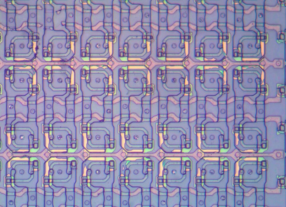
The double-poly process was also useful for shrinking the size of static RAM.3 The Ethernet chip contains several blocks of storage buffers for various purposes. These blocks are implemented as static RAM, including a 22×16 block, a 48×9 block, and a 16×7 block. The photo below shows a closeup of some storage cells, showing how they are arranged in a regular grid. The yellow lines of resistive polysilicon are visible in each cell.

A block of 28 storage cells in the chip. Some of the second polysilicon layer is damaged.

A block of 28 storage cells in the chip. Some of the second polysilicon layer is damaged.

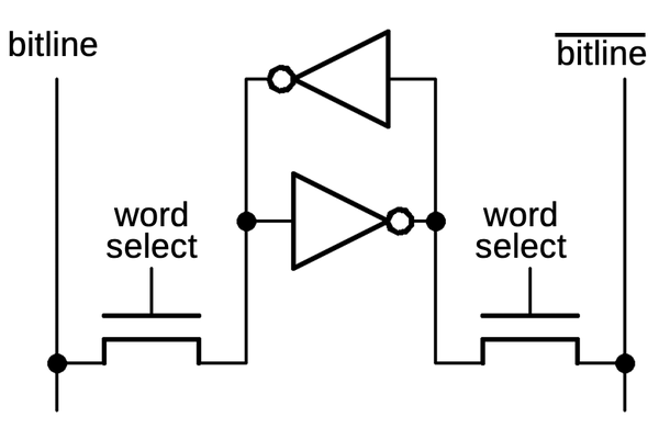
A static RAM storage cell is roughly similar to the latch cell, with two inverters in a loop to store each bit. However, the storage is arranged in a grid: each row corresponds to a particular word, and each column corresponds to the bits in a word. To select a word, a word select line is activated, turning on the pass transistors in that row. Reading and writing the cell is done through a pair of bitlines; each bit has a bitline and a complemented bitline. To read a word, the bits in the word are accessed through the bitlines. To write a word, the new value and its complement are applied to the bitlines, forcing the inverters into the desired state. (The bitlines must be driven with a high-current signal that can overcome the signal from the inverters.)

Schematic of one storage cell.

Schematic of one storage cell.

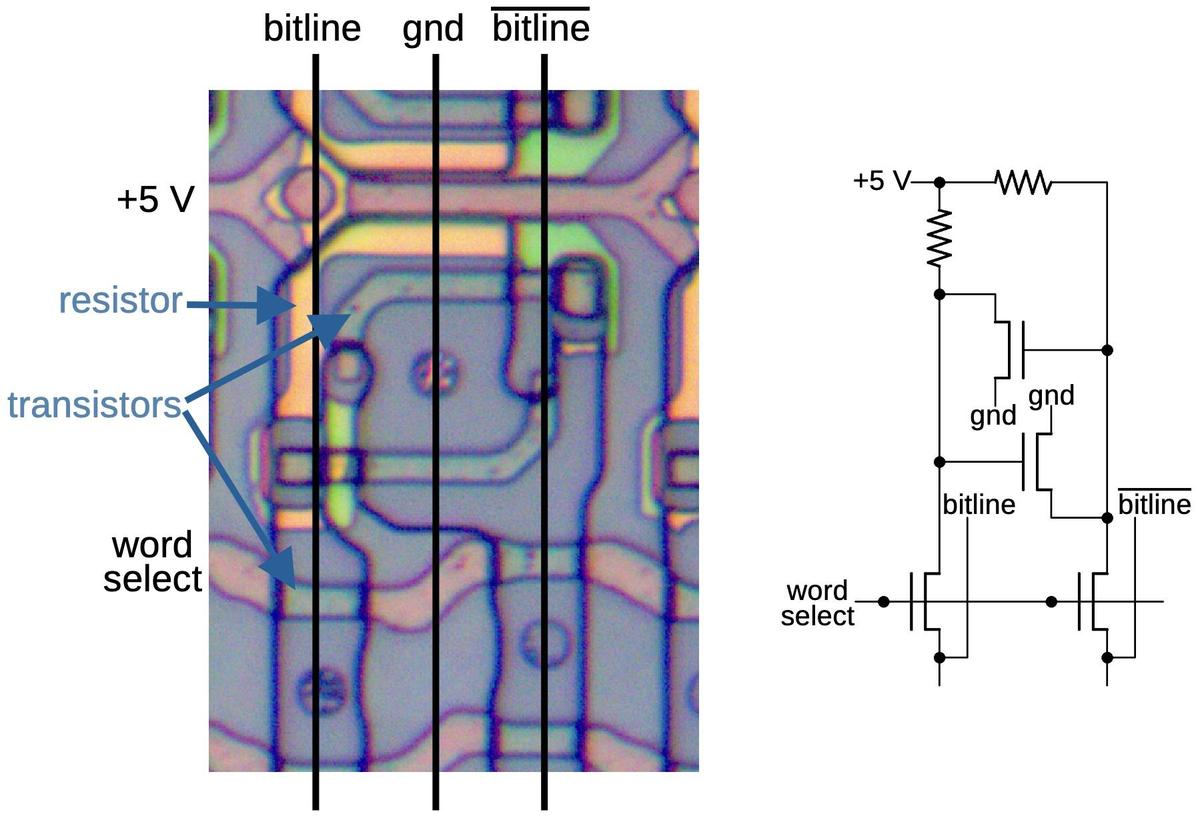
The diagram below shows the physical layout of one memory cell, consisting of two resistors and four transistors. The black lines indicate the vertical metal wiring that was removed. The schematic on the right corresponds to the physical arrangement of the circuit. Each inverter is constructed from a transistor and a pull-up resistor, and the inverters are connected into a loop. (The role of these resistors is completely different from the feedback resistors in the latch.) The two transistors at the bottom are the pass transistors that provide access to the cell for reads or writes.

One memory cell static memory cell as it appears on the die, along with its schematic.

One memory cell static memory cell as it appears on the die, along with its schematic.

The layout of this storage cell is highly optimized to minimize its area. Note that the yellow resistors take almost no additional area, as they overlap other parts of the cell. If constructed without resistors, each inverter would require an additional transistor, making the cell larger.

To summarize, although the double-poly process was introduced for DRAM capacitors, it can also be used for SRAM cell pull-up resistors. Reducing the size of the SRAM cells was probably the motivation to use this process for the Ethernet chip, with the latch feedback resistors a secondary benefit.

The Am7990 LANCE Ethernet chip

I'll wrap up with some background on the AMD Ethernet chip. Ethernet was invented in 1973 at Xerox PARC and became a standard in 1980. Ethernet was originally implemented with a board full of chips, mostly TTL. By the early 1980s, companies such as Intel, Seeq, and AMD introduced chips to put most of the circuitry onto VLSI chips. These chips reduced the complexity of Ethernet interface hardware, causing the price to drop from $2000 to $1000.

The chip that I'm examining is AMD's Am7990 LANCE (Local Area Network Controller for Ethernet). This chip implemented much of the functionality for Ethernet and "Cheapernet" (now known as 10BASE2 Ethernet). The chip handles serial/parallel conversion, computing the 32-bit CRC checksum, handling collisions and backoff, and recognizing desired addresses. The chip also provides DMA access for interfacing with a microcomputer.

The chip doesn't handle everything, though. It was designed to work with an Am7992 Serial Interface Adapter chip that encodes and decodes the bitstream using Manchester encoding. The third chip was the Am7996 transceiver that handled the low-level signaling and interfacing with the coaxial network cable, as well as detecting collisions if two nodes transmitted at the same time.

The LANCE chip is fairly complicated. The die photo below shows the main functional blocks of the chip. The chip is controlled by the large block of microcode ROM in the lower right. The large dark rectangles are storage, implemented with the static RAM cells described above. The chip has 48 pins, connected by tiny bond wires to the square pads around the edges of the die.

Main functional blocks of the LANCE chip.

Main functional blocks of the LANCE chip.

Thanks to Robert Garner for providing the AMD LANCE chip and information, thanks to a bunch of people on Twitter for discussion, and thanks to Bob Patel for providing the functional block labeling and other information. For more, follow me on Twitter @kenshirriff or RSS for updates. I'm also on Mastodon occasionally as @[email protected].

Notes and references

  1. It may seem contradictory for a weak inverter to be larger than a regular inverter, since you'd expect that the bigger the transistor, the stronger the signal. It turns out, however, that creating a weak signal requires a larger transistor, due to how MOS transistors are constructed. The current from a transistor is proportional to the gate's width divided by the length. Thus, to create a more powerful transistor, you increase the width. But to create a weak transistor, you can't decrease the width because the minimum width is limited by the manufacturing process. Thus, you need to increase the gate's length. The result is that both stronger and weaker transistors are larger than "normal" transistors. 

  2. You might worry that the feedback resistor will wastefully dissipate power. However, the feedback current is essentially zero because NMOS transistor gates are essentially insulators. Thus, the resistor only needs to pass enough current to charge or discharge the gate. 

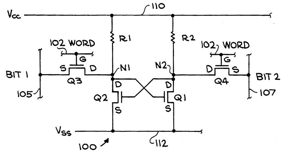
  3. An AMD patent describes the double-poly process as well as the static RAM cell; I'm not sure this is the process used in the Ethernet chip, but I expect the process is similar. The diagram below shows the RAM cell with its two resistors. The patent describes how the resistors and second layer of wiring are formed by a silicide/polysilicon ("inverted polycide") sandwich. (The silicide is a low-resistance compound of tantalum and silicon or molybdenum and silicon.) Specifically, the second layer consists of a buffer layer of polysilicon, a thicker silicide layer, and another layer of polysilicon forming the low-resistance "sandwich". Where resistance is desired, the bottom two layers of "sandwich" are removed during fabrication to leave just a layer of polysilicon. This polysilicon is then doped through implantation to give it the desired resistance.

    The static RAM cell from patent 4569122, "Method of forming a low resistance quasi-buried contact".

    The static RAM cell from patent 4569122, "Method of forming a low resistance quasi-buried contact".

    The patent also describes using the second layer of polysilicon to provide a connection between silicon and the main polysilicon layer. Chips normally use a "buried contact" to connect silicon and polysilicon, but the patent describes how putting the second layer of polysilicon on top reduces the alignment requirements for a low-resistance contact. I think this explains the yellow ring of polysilicon around all the silicon/polysilicon contacts in the chip. (These rings are visible in the die photo at the top of the article.) Patent 4581815 refines this process further.