While programmers today take division for granted, most microprocessors in the 1970s could only add and subtract — division required a slow and tedious loop implemented in assembly code. One of the nice features of the Intel 8086 processor (1978) was that it provided machine instructions for integer multiplication and division. Internally, the 8086 still performed a loop, but the loop was implemented in microcode: faster and transparent to the programmer. Even so, division was a slow operation, about 50 times slower than addition.
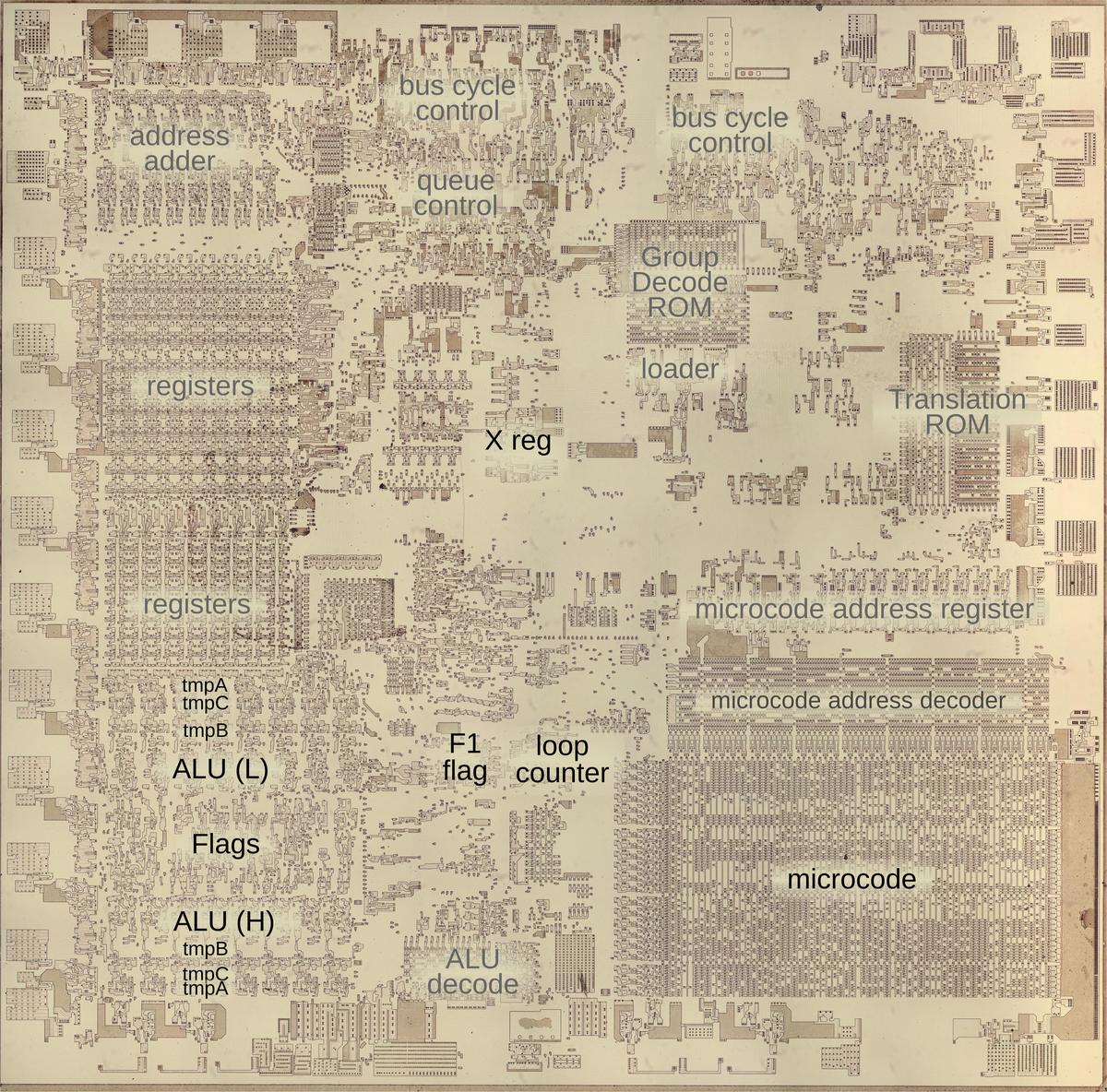
I recently examined multiplication in the 8086, and now it's time to look at the division microcode.1 (There's a lot of overlap with the multiplication post so apologies for any deja vu.) The die photo below shows the chip under a microscope. I've labeled the key functional blocks; the ones that are important to this post are darker. At the left, the ALU (Arithmetic/Logic Unit) performs the arithmetic operations at the heart of division: subtraction and shifts. Division also uses a few special hardware features: the X register, the F1 flag, and a loop counter. The microcode ROM at the lower right controls the process.
Microcode
Like most instructions, the division routines in the 8086 are implemented in microcode. Most people think of machine instructions as the basic steps that a computer performs. However, many processors have another layer of software underneath: microcode. With microcode, instead of building the CPU's control circuitry from complex logic gates, the control logic is largely replaced with code. To execute a machine instruction, the computer internally executes several simpler micro-instructions, specified by the microcode. This is especially useful for a machine instruction such as division, which performs many steps in a loop.
Each micro-instruction in the 8086 is encoded into 21 bits as shown below. Every micro-instruction moves data from a source register to a destination register, each specified with 5 bits. The meaning of the remaining bits depends on the type field and can be anything from an ALU operation to a memory read or write to a change of microcode control flow. Thus, an 8086 micro-instruction typically does two things in parallel: the move and the action. For more about 8086 microcode, see my microcode blog post.
A few details of the ALU (Arithmetic/Logic Unit) operations are necessary to understand the division microcode.
The ALU has three temporary registers that are invisible to the programmer: tmpA, tmpB, and tmpC.
An ALU operation takes its first argument from the specified temporary register, while the second argument always comes from tmpB.
An ALU operation requires two micro-instructions.
The first micro-instruction specifies the ALU operation and source register, configuring the ALU. For instance, ADD tmpA to add tmpA to the default tmpB.
In the next micro-instruction (or a later one), the ALU result can be accessed through a register called Σ (Sigma) and moved to another register.
The carry flag plays a key role in division.
The carry flag is one of the programmer-visible status flags that is set by arithmetic operations, but it is also used
by the microcode.
For unsigned addition, the carry flag is set if there is a carry out of the word (or byte).
For subtraction, the carry flag indicates a borrow, and is set if the subtraction requires a borrow.
Since a borrow results if you subtract a larger number from a smaller number, the carry flag also indicates
the "less than" condition.
The carry flag (and other status flags) are only updated if micro-instruction contains the F bit.
The RCL (Rotate through Carry, Left) micro-instruction is heavily used in the division microcode.2
This operation shifts the bits in a 16-bit word, similar to the << bit-shift operation in high-level languages, but with an additional feature.
Instead of discarding the bit on the end, that bit is moved into the carry flag. Meanwhile, the bit formerly in the carry flag moves into the word.
You can think of this as rotating the bits while treating the carry flag as a 17th bit of the word.
(The RCL operation can also act on a byte.)
These shifts perform an important part of the division process since shifting can be viewed as multiplying or dividing by two.
RCL also provides a convenient way to move the most-significant bit to the carry flag, where it can be tested for a conditional jump.
(This is important because the top bit is used as the sign bit.)
Another important property is that performing RCL on a lower word and then RCL on an upper word will perform a 32-bit shift, since
the high bit of the lower word will be moved into the low bit of the upper word via the carry bit.
Finally, the shift moves the quotient bit from the carry into the register.
Binary division
The division process in the 8086 is similar to grade-school long division, except in binary instead of decimal. The diagram below shows the process: dividing 67 (the dividend) by 9 (the divisor) yields the quotient 7 at the top and the remainder 4 at the bottom. Long division is easier in binary than decimal because you don't need to guess the right quotient digit. Instead, at each step you either subtract the divisor (appropriately shifted) or subtract nothing. Note that although the divisor is 4 bits in this example, the subtractions use 5-bit values. The need for an "extra" bit in division will be important in the discussion below; 16-bit division needs a 17-bit value.
| 0 | 1 | 1 | 1 | ||||||||
| 1 | 0 | 0 | 1 | 0 | 1 | 0 | 0 | 0 | 0 | 1 | 1 |
| - | 0 | 0 | 0 | 0 | |||||||
| 1 | 0 | 0 | 0 | 0 | |||||||
| - | 1 | 0 | 0 | 1 | |||||||
| 0 | 1 | 1 | 1 | 1 | |||||||
| - | 1 | 0 | 0 | 1 | |||||||
| 0 | 1 | 1 | 0 | 1 | |||||||
| - | 1 | 0 | 0 | 1 | |||||||
| 0 | 1 | 0 | 0 | ||||||||
Instead of shifting the divisor to the right each step, the 8086's algorithm shifts the quotient and the current dividend to the left each step. This trick reduces the register space required. Dividing a 32-bit number (the dividend) by a 16-bit number yields a 16-bit result, so it seems like you'd need four 16-bit registers in total. The trick is that after each step, the 32-bit dividend gets one bit smaller, while the result gets one bit larger. Thus, the dividend and the result can be packed together into 32 bits. At the end, what's left of the dividend is the 16-bit remainder. The table below illustrates this process for a sample dividend (blue) and quotient (green).3 At the end, the 16-bit blue value is the remainder.
| dividend | quotient | ||||||||||||||||||||||||||||||
|---|---|---|---|---|---|---|---|---|---|---|---|---|---|---|---|---|---|---|---|---|---|---|---|---|---|---|---|---|---|---|---|
| 0 | 0 | 0 | 0 | 1 | 1 | 1 | 1 | 0 | 0 | 0 | 0 | 0 | 0 | 0 | 0 | 1 | 1 | 1 | 1 | 1 | 1 | 1 | 1 | 0 | 0 | 0 | 0 | 0 | 0 | 0 | 0 |
| 0 | 0 | 0 | 0 | 1 | 1 | 1 | 0 | 0 | 0 | 0 | 0 | 0 | 1 | 0 | 1 | 1 | 1 | 1 | 1 | 1 | 1 | 1 | 0 | 0 | 0 | 0 | 0 | 0 | 0 | 0 | 0 |
| 0 | 0 | 0 | 0 | 1 | 1 | 0 | 0 | 0 | 0 | 0 | 0 | 1 | 1 | 1 | 1 | 1 | 1 | 1 | 1 | 1 | 1 | 0 | 0 | 0 | 0 | 0 | 0 | 0 | 0 | 0 | 0 |
| 0 | 0 | 0 | 0 | 1 | 0 | 0 | 0 | 0 | 0 | 1 | 0 | 0 | 0 | 1 | 1 | 1 | 1 | 1 | 1 | 1 | 0 | 0 | 0 | 0 | 0 | 0 | 0 | 0 | 0 | 0 | 0 |
| 0 | 0 | 0 | 0 | 0 | 0 | 0 | 0 | 0 | 1 | 0 | 0 | 1 | 0 | 1 | 1 | 1 | 1 | 1 | 1 | 0 | 0 | 0 | 0 | 0 | 0 | 0 | 0 | 0 | 0 | 0 | 0 |
| 0 | 0 | 0 | 0 | 0 | 0 | 0 | 0 | 1 | 0 | 0 | 1 | 0 | 1 | 1 | 1 | 1 | 1 | 1 | 0 | 0 | 0 | 0 | 0 | 0 | 0 | 0 | 0 | 0 | 0 | 0 | 1 |
| 0 | 0 | 0 | 0 | 0 | 0 | 0 | 1 | 0 | 0 | 1 | 0 | 1 | 1 | 1 | 1 | 1 | 1 | 0 | 0 | 0 | 0 | 0 | 0 | 0 | 0 | 0 | 0 | 0 | 0 | 1 | 1 |
| 0 | 0 | 0 | 0 | 0 | 0 | 1 | 0 | 0 | 1 | 0 | 1 | 1 | 1 | 1 | 1 | 1 | 0 | 0 | 0 | 0 | 0 | 0 | 0 | 0 | 0 | 0 | 0 | 0 | 1 | 1 | 1 |
| 0 | 0 | 0 | 0 | 0 | 1 | 0 | 0 | 1 | 0 | 1 | 1 | 1 | 1 | 1 | 1 | 0 | 0 | 0 | 0 | 0 | 0 | 0 | 0 | 0 | 0 | 0 | 0 | 1 | 1 | 1 | 1 |
| 0 | 0 | 0 | 0 | 1 | 0 | 0 | 1 | 0 | 1 | 1 | 1 | 1 | 1 | 1 | 0 | 0 | 0 | 0 | 0 | 0 | 0 | 0 | 0 | 0 | 0 | 0 | 1 | 1 | 1 | 1 | 1 |
| 0 | 0 | 0 | 0 | 0 | 0 | 1 | 1 | 0 | 0 | 0 | 0 | 0 | 0 | 0 | 0 | 0 | 0 | 0 | 0 | 0 | 0 | 0 | 0 | 0 | 0 | 1 | 1 | 1 | 1 | 1 | 0 |
| 0 | 0 | 0 | 0 | 0 | 1 | 1 | 0 | 0 | 0 | 0 | 0 | 0 | 0 | 0 | 0 | 0 | 0 | 0 | 0 | 0 | 0 | 0 | 0 | 0 | 1 | 1 | 1 | 1 | 1 | 0 | 1 |
| 0 | 0 | 0 | 0 | 1 | 1 | 0 | 0 | 0 | 0 | 0 | 0 | 0 | 0 | 0 | 0 | 0 | 0 | 0 | 0 | 0 | 0 | 0 | 0 | 1 | 1 | 1 | 1 | 1 | 0 | 1 | 1 |
| 0 | 0 | 0 | 0 | 1 | 0 | 0 | 0 | 0 | 0 | 0 | 0 | 0 | 1 | 0 | 0 | 0 | 0 | 0 | 0 | 0 | 0 | 0 | 1 | 1 | 1 | 1 | 1 | 0 | 1 | 1 | 0 |
| 0 | 0 | 0 | 0 | 0 | 0 | 0 | 0 | 0 | 0 | 0 | 0 | 1 | 1 | 0 | 0 | 0 | 0 | 0 | 0 | 0 | 0 | 1 | 1 | 1 | 1 | 1 | 0 | 1 | 1 | 0 | 0 |
| 0 | 0 | 0 | 0 | 0 | 0 | 0 | 0 | 0 | 0 | 0 | 1 | 1 | 0 | 0 | 0 | 0 | 0 | 0 | 0 | 0 | 1 | 1 | 1 | 1 | 1 | 0 | 1 | 1 | 0 | 0 | 1 |
| 0 | 0 | 0 | 0 | 0 | 0 | 0 | 0 | 0 | 0 | 1 | 1 | 0 | 0 | 0 | 0 | 0 | 0 | 0 | 0 | 1 | 1 | 1 | 1 | 1 | 0 | 1 | 1 | 0 | 0 | 1 | 1 |
The division microcode
The 8086 has four division instructions to handle signed and unsigned division of byte and word operands.
I'll start by describing the microcode for the unsigned word division instruction DIV, which divides a 32-bit dividend by a 16-bit divisor.
The dividend is supplied in the AX and DX registers while the divisor is specified by the source operand.
The 16-bit quotient is returned in AX and the 16-bit remainder in DX.
For a divide-by-zero, or if the quotient is larger than 16 bits, a type 0 "divide error" interrupt is generated.
CORD: The core division routine
The CORD microcode subroutine below implements the long-division algorithm for all division instructions; I think CORD stands for Core Divide.
At entry, the arguments are in the ALU temporary registers:
tmpA/tmpC hold the 32-bit dividend, while tmpB holds the 16-bit divisor.
(I'll explain the configuration for byte division later.)
Each cycle of the loop shifts the values and then potentially subtracts the divisor.
One bit is appended to the quotient to indicate whether the
divisor was subtracted or not.
At the end of the loop, whatever is left of the dividend is the remainder.
Each micro-instruction specifies a register move on the left, and an action on the right.
The moves transfer words between the visible registers and the ALU's temporary registers, while the actions are mostly ALU operations or control flow.
As is usually the case with microcode, the details are tricky.
The first three lines below check if the division will overflow or divide by zero.
The code compares tmpA and tmpB by subtracting tmpB, discarding the result, but setting the status flags (F).
If the upper word of the divisor is greater or equal to the dividend, the division will overflow, so execution jumps to INT0 to generate
a divide-by-zero interrupt.4 (This handles both the case where the dividend is "too large" and the divide-by-0 case.)
The number of loops in the division algorithm is controlled by a special-purpose loop counter.
The MAXC micro-instruction initializes the counter to 7 or 15, for a byte or word divide instruction respectively.
   move        action
             SUBT tmpA   CORD: set up compare
Σ → no dest  MAXC F       compare, set up counter, update flags
             JMP NCY INT0 generate interrupt if overflow
             RCL tmpC    3: main loop: left shift tmpA/tmpC
Σ → tmpC     RCL tmpA
Σ → tmpA     SUBT tmpA    set up compare/subtract
             JMPS CY 13   jump if top bit of tmpA was set
Σ → no dest  F            compare, update flags
             JMPS NCY 14  jump for subtract
             JMPS NCZ 3   test counter, loop back to 3
             RCL tmpC    10: done:
Σ → tmpC                  shift last bit into tmpC
Σ → no dest  RTN          done: get top bit, return

             RCY         13: reset carry
Σ → tmpA     JMPS NCZ 3  14: subtract, loop
             JMPS 10     done, goto 10
The main loop starts at 3.
The tmpC and tmpA registers are shifted left. This has two important side effects. First, the old carry bit (which holds the latest
quotient bit) is shifted into the bottom of tmpC. Second, the top bit of tmpA is shifted into the carry bit;
this provides the necessary "extra" bit for the subtraction below.
Specifically, if the carry (the "extra" tmpA bit) is set, tmpB can be subtracted, which is accomplished by jumping to 13.
Otherwise, the code compares tmpA and tmpB by
subtracting tmpB, discarding the result, and updating the flags (F).
If there was no borrow/carry (tmpA ≥ tmpB), execution jumps to 14 to subtract.
Otherwise, the internal loop counter is decremented and control flow goes back to the top of the loop if not done
(NCZ, Not Counter Zero).
If the loop is done, tmpC is rotated left to pick up the last quotient bit from the carry flag.
Then a second rotate of tmpC is performed but the result is discarded; this puts the top bit of tmpC into the carry flag for
use later in POSTIDIV. Finally, the subroutine returns.
The subtraction path is 13 and 14, which subtract tmpB from tmpA by storing the result (Σ) in tmpA.
This path resets the carry flag for use as the quotient bit.
As in the other path, the loop counter is decremented and tested (NCZ) and execution either continues back at 3
or finishes at 10.
One complication is that the carry bit is the opposite of the desired quotient bit. Specifically, if tmpA < tmpB, the comparison generates a borrow so the carry flag is set to 1. In this case, the desired quotient bit is 0 and no subtraction takes place. But if tmpA ≥ tmpB, the comparison does not generate a borrow (so the carry flag is set to 0), the code subtracts tmpB, and the desired quotient bit is 1. Thus, tmpC ends up holding the complement of the desired result; this is fixed later.
The microcode is carefully designed to pack the divide loop into a small number of micro-instructions. It uses the registers and the carry flag in tricky ways, using the carry flag to hold the top bit of tmpA, the comparison result, and the generated quotient bit. This makes the code impressively dense but tricky to understand.
The top-level division microcode
Now I'll pop up a level and take a look at the top-level microcode (below) that implements the DIV and IDIV machine instructions.
The first three instructions load tmpA, tmpC, and tmpB from the specified registers.
(The M register refers to the source specified in the instruction, either a register or a memory location.)
Next, the X0 condition tests bit 3 of the instruction, which in this case distinguishes DIV from IDIV.
For signed division (IDIV), the microcode calls PREIDIV, which I'll discuss below.
Next, the CORD micro-subroutine discussed above is called to perform the division.
DX → tmpA                      iDIV rmw: load tmpA, tmpC, tmpB
AX → tmpC    RCL tmpA           set up RCL left shift operation
M → tmpB     CALL X0 PREIDIV    set up integer division if IDIV
             CALL CORD          call CORD to perform division
             COM1 tmpC          set up to complement the quotient
DX → tmpB    CALL X0 POSTIDIV   get original dividend, handle IDIV
Σ → AX       NXT                store updated quotient
tmpA → DX    RNI                store remainder, run next instruction
As discussed above, the quotient in tmpC needs to be 1's-complemented, which is done with COM1.
For IDIV, the micro-subroutine POSTIDIV sets the signs of the results appropriately.
The results are stored in the AX and DX registers.
The NXT micro-operation indicates the next micro-instruction is the last one, directing the microcode engine to
start the next
machine instruction. Finally, RNI directs the microcode engine to run the next machine instruction.
8-bit division
The 8086 has separate opcodes for 8-bit division.
The 8086 supports many instructions with byte and word versions, using 8-bit or 16-bit arguments respectively.
In most cases, the byte and word instructions use the same microcode, with the ALU and register hardware using bytes or words based on the instruction.
In the case of division,
the shift micro-operations act on tmpA and tmpC as 8-bit registers rather than 16-bit registers.
Moreover, the MAXC micro-operation initializes the internal counter to 7 rather than 15.
Thus, the same CORD microcode is used for word and byte division, but the number of loops and the specific
operations are changed by the hardware.
The diagram below shows the tmpA and tmpC registers during each step of dividing 0x2345 by 0x34. Note that the registers are treated as 8-bit registers. The divisor (blue) steadily shrinks with the quotient (green) taking its place. At the end, the remainder is 0x41 (blue) and the quotient is 0xad, complement of the green value.
| tmpA | tmpC | ||||||||||||||||||||||||||||||
|---|---|---|---|---|---|---|---|---|---|---|---|---|---|---|---|---|---|---|---|---|---|---|---|---|---|---|---|---|---|---|---|
| 0 | 0 | 0 | 0 | 0 | 0 | 0 | 0 | 0 | 0 | 1 | 0 | 0 | 0 | 1 | 1 | 0 | 0 | 0 | 0 | 0 | 0 | 0 | 0 | 0 | 1 | 0 | 0 | 0 | 1 | 0 | 1 |
| 0 | 0 | 0 | 0 | 0 | 0 | 0 | 0 | 0 | 0 | 0 | 1 | 0 | 0 | 1 | 0 | 0 | 0 | 0 | 0 | 0 | 0 | 0 | 0 | 1 | 0 | 0 | 0 | 1 | 0 | 1 | 0 |
| 0 | 0 | 0 | 0 | 0 | 0 | 0 | 0 | 0 | 0 | 1 | 0 | 0 | 1 | 0 | 1 | 0 | 0 | 0 | 0 | 0 | 0 | 0 | 0 | 0 | 0 | 0 | 1 | 0 | 1 | 0 | 1 |
| 0 | 0 | 0 | 0 | 0 | 0 | 0 | 0 | 0 | 0 | 0 | 1 | 0 | 1 | 1 | 0 | 0 | 0 | 0 | 0 | 0 | 0 | 0 | 0 | 0 | 0 | 1 | 0 | 1 | 0 | 1 | 0 |
| 0 | 0 | 0 | 0 | 0 | 0 | 0 | 0 | 0 | 0 | 1 | 0 | 1 | 1 | 0 | 0 | 0 | 0 | 0 | 0 | 0 | 0 | 0 | 0 | 0 | 1 | 0 | 1 | 0 | 1 | 0 | 1 |
| 0 | 0 | 0 | 0 | 0 | 0 | 0 | 0 | 0 | 0 | 1 | 0 | 0 | 1 | 0 | 0 | 0 | 0 | 0 | 0 | 0 | 0 | 0 | 0 | 1 | 0 | 1 | 0 | 1 | 0 | 1 | 0 |
| 0 | 0 | 0 | 0 | 0 | 0 | 0 | 0 | 0 | 0 | 0 | 1 | 0 | 1 | 0 | 1 | 0 | 0 | 0 | 0 | 0 | 0 | 0 | 0 | 0 | 1 | 0 | 1 | 0 | 1 | 0 | 0 |
| 0 | 0 | 0 | 0 | 0 | 0 | 0 | 0 | 0 | 0 | 1 | 0 | 1 | 0 | 1 | 0 | 0 | 0 | 0 | 0 | 0 | 0 | 0 | 0 | 1 | 0 | 1 | 0 | 1 | 0 | 0 | 1 |
| 0 | 0 | 0 | 0 | 0 | 0 | 0 | 0 | 0 | 0 | 1 | 0 | 0 | 0 | 0 | 1 | 0 | 0 | 0 | 0 | 0 | 0 | 0 | 0 | 0 | 1 | 0 | 1 | 0 | 0 | 1 | 0 |
Although the CORD routine is shared for byte and word division, the top-level microcode is different.
In particular, the byte and word division instructions use different registers, requiring microcode changes.
The microcode below is the top-level code for byte division. It is almost the same as the microcode above, except it
uses the top and bottom bytes of the accumulator (AH and AL) rather than the AX and DX registers.
AH → tmpA                     iDIV rmb: get arguments
AL → tmpC    RCL tmpA          set up RCL left shift operation
M → tmpB     CALL X0 PREIDIV   handle signed division if IDIV
             CALL CORD         call CORD to perform division
             COM1 tmpC         complement the quotient
AH → tmpB    CALL X0 POSTIDIV  handle signed division if IDIV
Σ → AL       NXT               store quotient
tmpA → AH    RNI               store remainder, run next instruction
Signed division
The 8086 (like most computers) represents signed numbers using a format called two's complement.
While a regular byte holds a number from 0 to 255, a signed byte holds a number from -128 to 127.
A negative number is formed by flipping all the bits (known as the one's complement) and then adding 1, yielding the two's complement value.
For instance, +5 is 0x05 while -5 is 0xfb.
(Note that the top bit of a number is set for a negative number; this is the sign bit.)
The nice thing about two's complement numbers is that the same addition and subtraction operations work on both signed and unsigned values.
Unfortunately, this is not the case for signed multiplication and division.
The 8086 has separate IDIV (Integer Divide) instructions to perform signed division.
The 8086 performs signed division by converting the arguments to positive values, performing unsigned division, and then
negating the results if necessary.
As shown earlier, signed and unsigned division both use the same top-level microcode and the microcode conditionally calls some subroutines for
signed division.
These additional subroutines cause a significant performance penalty, making signed division over 20 cycles slower than unsigned division.
I will discuss those micro-subroutines below.
PREIDIV
The first subroutine for signed division is PREIDIV, performing preliminary operations for integer division.
It converts the two arguments, stored in tmpA/tmpC and tmpB, to positive values.
It keeps track of the signs using an internal flag called F1, toggling this flag for each negative argument.
This conveniently handles the rule that two negatives make a positive since complementing the F1 flag twice will clear it.
The point of this is that the main division code (CORD) only needs to handle unsigned division.
The microcode below implements PREIDIV.
First it tests if tmpA is negative, but
the 8086 does not have a microcode condition to directly test the sign of a value.
Instead, the microcode determines if a value is negative by shifting the value left, which moves the top (sign) bit into the carry flag.
The conditional jump (NCY) then tests if the carry is clear, jumping if the value is non-negative.
If tmpA is negative, execution falls through to negate the first argument.
This is tricky because the argument is split between the tmpA and tmpC registers.
The two's complement operation (NEG) is applied to the low word, while either 2's complement or one's complement (COM1) is applied to
the upper word, depending on the carry for mathematical reasons.5
The F1 flag is complemented to keep track of the sign.
(The multiplication process reuses most of this code, starting at the NEGATE entry point.)
Σ → no dest             PREIDIV: shift tmpA left
             JMPS NCY 7  jump if non-negative
             NEG tmpC   NEGATE: negate tmpC
Σ → tmpC     COM1 tmpA F maybe complement tmpA
             JMPS CY 6
             NEG tmpA    negate tmpA if there's no carry
Σ → tmpA     CF1        6: toggle F1 (sign)

             RCL tmpB  7: test sign of tmpB
Σ → no dest  NEG tmpB    maybe negate tmpB
             JMPS NCY 11 skip if tmpB positive
Σ → tmpB     CF1 RTN     else negate tmpB, toggle F1 (sign)
             RTN        11: return
The next part of the code, starting at 7, negates tmpB (the divisor) if it is negative. Since the divisor is a single
word, this code is simpler.
As before, the F1 flag is toggled if tmpB is negative.
At the end, both arguments (tmpA/tmpC and tmpB) are positive, and F1 indicates the sign of the result.
POSTIDIV
After computing the result, the POSTIDIV routine is called for signed division.
The routine first checks for a signed overflow and raises a divide-by-zero interrupt if so.
Next, the routine negates the quotient and remainder if necessary.6
In more detail, the CORD routine left the top bit of tmpC (the complemented quotient) in the carry flag.
Now, that bit is tested. If the carry bit is 0 (NCY), then the top bit of the quotient is 1 so the quotient is too big to fit in a signed value.7
In this case, the INT0 routine is executed to trigger a type 0 interrupt, indicating a divide overflow.
(This is a rather roundabout way of testing the quotient, relying on a carry bit that was set in a previous subroutine.)
             JMP NCY INT0 POSTIDIV: if overflow, trigger interrupt
             RCL tmpB      set up rotate of tmpB
Σ → no dest  NEG tmpA      get sign of tmpB, set up negate of tmpA
             JMPS NCY 5    skip if tmpB non-negative
Σ → tmpA                   otherwise negate tmpA (remainder)
             INC tmpC     5: set up increment
             JMPS F1 8     test sign flag, skip if set
             COM1 tmpC     otherwise set up complement
             CCOF RTN     8: clear carry and overflow flags, return
Next, tmpB (the divisor) is rotated to see if it is negative. (The caller loaded tmpB with the original divisor, replacing the dividend that was in tmpB previously.) If the divisor is negative, tmpA (the remainder) is negated. This implements the 8086 rule that the sign of the remainder matches the sign of the divisor.
The quotient handling is a bit tricky. Recall that tmpC holds the complemented quotient.
the F1 flag is set if the result should be negative. In that case, the complemented quotient needs to be incremented
by 1 (INC) to convert from 1's complement to 2's complement.
On the other hand, if the quotient should be positive, 1's-complementing tmpC (COM1) will yield the desired positive
quotient.
In either case, the ALU is configured in POSTIDIV, but the result will be stored back in the main routine.
Finally, the CCOF micro-operation clears the carry and overflow flags.
Curiously, the 8086 documentation declares that the status flags are undefined following IDIV, but the microcode
explicitly clears the carry and overflow flags.
I assume that the flags were cleared in analogy with MUL, but then Intel decided that this wasn't useful so they
didn't document it. (Documenting this feature would obligate them to provide the same functionality in later x86 chips.)
The hardware for division
For the most part, the 8086 uses the regular ALU addition and shifts for the division algorithm. Some special hardware features provide assistance. In this section, I'll look at this hardware.
Loop counter
The 8086 has a 4-bit loop counter for multiplication and division. This counter starts at 7 for byte division and 15 for word division,
based on the low bit of the opcode.
This loop counter allows the microcode to decrement the counter, test for the end, and perform a conditional branch in one micro-operation.
The counter is implemented with four flip-flops, along with logic to compute the value after decrementing by one.
The MAXC (Maximum Count) micro-instruction sets the counter to 7 or 15 for byte or word operations respectively.
The NCZ (Not Counter Zero) micro-instruction has two actions. First, it performs a conditional jump if the counter is nonzero.
Second, it decrements the counter.
The F1 flag
Signed multiplication and division use an internal flag called F18 to keep track of the sign.
The F1 flag is toggled by microcode through the CF1 (Complement F1) micro-instruction.
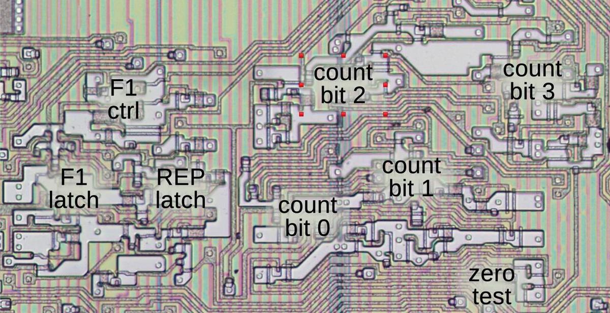
The F1 flag is implemented with a flip-flop, along with a multiplexer to select the value. It is cleared when a new instruction starts,
set by a REP prefix, and toggled by the CF1 micro-instruction.
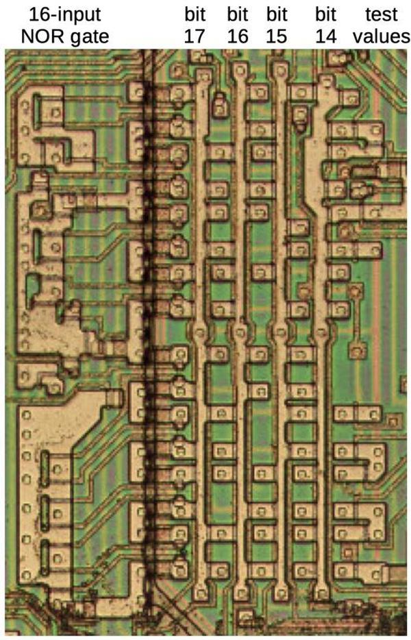
The diagram below shows how the F1 latch and the loop counter appear on the die. In this image, the metal layer has been removed, showing the
silicon and the polysilicon wiring underneath.
X register
The division microcode uses an internal register called the X register to distinguish between the DIV and IDIV instructions.
The X register is a 3-bit register that holds the ALU opcode, indicated by bits 5–3 of the instruction.9
Since the instruction is held in the Instruction Register, you might wonder why a separate register is required.
The motivation is that some opcodes specify the type of ALU operation in the second byte of the instruction, the ModR/M byte, bits 5–3.10
Since the ALU operation is sometimes specified in the first byte and sometimes in the second byte, the X register was added to handle
both these cases.
For the most part, the X register indicates which of the eight standard ALU operations is selected (ADD, OR, ADC, SBB, AND, SUB, XOR, CMP).
However, a few instructions use bit 0 of the X register to distinguish between other pairs of instructions.
For instance, it distinguishes between MUL and IMUL, DIV and IDIV, CMPS and SCAS, MOVS and LODS, or AAA and AAS.
While these instruction pairs may appear to have arbitrary opcodes, they have been carefully assigned
so the microcode can distinguish them.
The implementation of the X register is straightforward, consisting of three flip-flops to hold the three bits of the instruction.
The flip-flops are loaded from the prefetch queue bus during First Clock and during Second Clock for appropriate instructions, as the
instruction bytes travel over the bus.
Testing bit 0 of the X register with the X0 condition is supported by the microcode condition evaluation circuitry, so it can be used for conditional jumps in the microcode.
Algorithmic and historical context
As you can see from the microcode, division is a complicated and relatively slow process. On the 8086, division takes up to 184 clock cycles to perform all the microcode steps. (In comparison, two registers can be added in 3 clock cycles.) Multiplication and division both loop over the bits, performing repeated addition or subtraction respectively. But division requires a decision (subtract or not?) at each step, making it even slower, about half the speed of multiplication.11
Various algorithms have been developed to speed up division. Rather than performing long division one bit at a time, you can do long division in, say, base 4, producing two quotient bits in each step. As with decimal long division, the tricky part is figuring out what digit to select. The SRT algorithm (1957) uses a small lookup table to estimate the quotient digit from a few bits of the divisor and dividend. The clever part is that the selected digit doesn't need to be exactly right at each step; the algorithm will self-correct after a wrong "guess". The Pentium processor (1993) famously had a floating point division bug due to a few missing values in the SRT table. This bug cost Intel $475 million to replace the faulty processors.
Intel's x86 processors steadily improved divide performance. The 80286 (1982) performed a word divide in 22 clocks, about 6 times as fast as the 8086. In the Penryn architecture (2007), Intel upgraded from Radix-4 to Radix-16 division. Rather than having separate integer and floating-point hardware, integer divides were handled through the floating point divider. Although modern Intel processors have greatly improved multiplication and division compared to the 8086, division is still a relatively slow operation. While a Tiger Lake (2020) processor can perform an integer multiplication every clock cycle (with a latency of 3 cycles), division is much slower and can only be done once every 6-10 clock cycles (details).
I've written numerous posts on the 8086 so far and plan to continue reverse-engineering the 8086 die so follow me on Twitter @kenshirriff or RSS for updates. I've also started experimenting with Mastodon recently as @[email protected].
Notes and references
-
My microcode analysis is based on Andrew Jenner's 8086 microcode disassembly. ↩
-
The 8086 patent and Andrew Jenner's microcode use the name
LRCY(Left Rotate through Carry) instead ofRCL. I figure thatRCLwill be more familiar to people because of the corresponding machine instruction. ↩ -
In the dividend/quotient table, the tmpA register is on the left and the tmpC register is on the right. 0x0f00ff00 divided by 0x0ffc yielding the remainder 0x0030 (blue) and quotient 0xf04c (green). (The green bits are the complement of the quotient due to implementation in the 8086.) ↩
-
I described the 8086's interrupt circuitry in detail in this post. ↩
-
The negation code is a bit tricky because the result is split across two words. In most cases, the upper word is bitwise complemented. However, if the lower word is zero, then the upper word is negated (two's complement). I'll demonstrate with 16-bit values to keep the examples small. The number 257 (0x0101) is negated to form -257 (0xfeff). Note that the upper byte is the one's complement (0x01 vs 0xfe) while the lower byte is two's complement (0x01 vs 0xff). On the other hand, the number 256 (0x0100) is negated to form -256 (0xff00). In this case, the upper byte is the two's complement (0x01 vs 0xff) and the lower byte is also the two's complement (0x00 vs 0x00).
(Mathematical explanation: the two's complement is formed by taking the one's complement and adding 1. In most cases, there won't be a carry from the low byte to the upper byte, so the upper byte will remain the one's complement. However, if the low byte is 0, the complement is 0xff and adding 1 will form a carry. Adding this carry to the upper byte yields the two's complement of that byte.)
To support multi-word negation, the 8086's
NEGinstruction clears the carry flag if the operand is 0, and otherwise sets the carry flag. (This is the opposite of the above because subtractions (includingNEG) treat the carry flag as a borrow flag, with the opposite meaning.) The microcodeNEGoperation has identical behavior to the machine instruction, since it is used to implement the machine instruction.Thus to perform a two-word negation, the microcode negates the low word (tmpC) and updates the flags (
F). If the carry is set, the one's complement is applied to the upper word (tmpA). But if the carry is cleared, the two's complement is applied to tmpA. ↩ -
There is a bit of ambiguity with the quotient and remainder of negative numbers. For instance, consider -27 ÷ 7. -27 = 7 × -3 - 6 = 7 * -4 + 1. So you could consider the result to be a quotient of -3 and remainder of -6, or a quotient of -4 and a remainder of 1. The 8086 uses the rule that the remainder will have the same sign as the dividend, so the first result would be used. The advantage of this rule is that you can perform unsigned division and adjust the signs afterward:
27 ÷ 7 = quotient 3, remainder 6.
-27 ÷ 7 = quotient -3, remainder -6.
27 ÷ -7 = quotient -3, remainder 6.
-27 ÷ -7 = quotient 3, remainder -6.This rule is known as truncating division, but some languages use different approaches such as floored division, rounded division, or Euclidean division. Wikipedia has details. ↩
-
The signed overflow condition is slightly stricter than necessary. For a word division, the 16-bit quotient is restricted to the range -32767 to 32767. However, a 16-bit signed value can take on the values -32768 to 32767. Thus, a quotient of -32768 fits in a 16-bit signed value even though the 8086 considers it an error. This is a consequence of the 8086 performing unsigned division and then updating the sign if necessary. ↩
-
The internal
F1flag is also used to keep track of aREPprefix for use with a string operation. I discussed string operations and theF1flag in this post. ↩ -
Curiously, the 8086 patent states that the
Xregister is a 4-bit register holding bits 3–6 of the byte (col. 9, line 20). But looking at the die, it is a 3-bit register holding bits 3–5 of the byte. ↩ -
Some instructions are specified by bits 5–3 in the ModR/M byte rather than in the first opcode byte. The motivation is to avoid wasting bits for instructions that use a ModR/M byte but don't need a register specification. For instance, consider the instruction
ADD [BX],0x1234. This instruction uses a ModR/M byte to specify the memory address. However, because it uses an immediate operand, it does not need the register specification normally provided by bits 5–3 of the ModR/M byte. This frees up the bits to specify the instruction. From one perspective, this is an ugly hack, while from another perspective it is a clever optimization. ↩ -
Even the earliest computers such as ENIAC (1945) usually supported multiplication and division. However, early microprocessors did not provide multiplication and division instructions due to the complexity of these instructions. Instead, the programmer would need to write an assembly code loop, which was very slow. Early microprocessors often had binary-coded decimal instructions that could perform additions and subtractions in decimal. One motivation for these instructions was that converting between binary and decimal was extremely slow due to the need for multiplication and division. Instead, it was easier and faster to keep the values as decimal if that was how they were displayed.
The Texas Instruments TMS9900 (1976) was one of the first microprocessors with multiplication and division instructions. Multiply and divide instructions remained somewhat controversial on RISC (Reduced Instruction-Set Computer) processors due to the complexity of these instructions. The early ARM processors, for instance, did not support multiplication and division. Multiplication was added to ARMv2 (1986) but most ARM processors still don't have integer division. The popular open-source RISC-V architecture (2015) doesn't include integer multiply and divide by default, but provides them as an optional "M" extension.
The 8086's algorithm is designed for simplicity rather than speed. It is a "restoring" algorithm that checks before subtracting to ensure that the current term is always positive. This can require two ALU operations (comparison and subtraction) per cycle. A slightly more complex approach is a "nonrestoring" algorithm that subtracts even if it yields a negative term, and then adds during a later loop iteration. ↩
