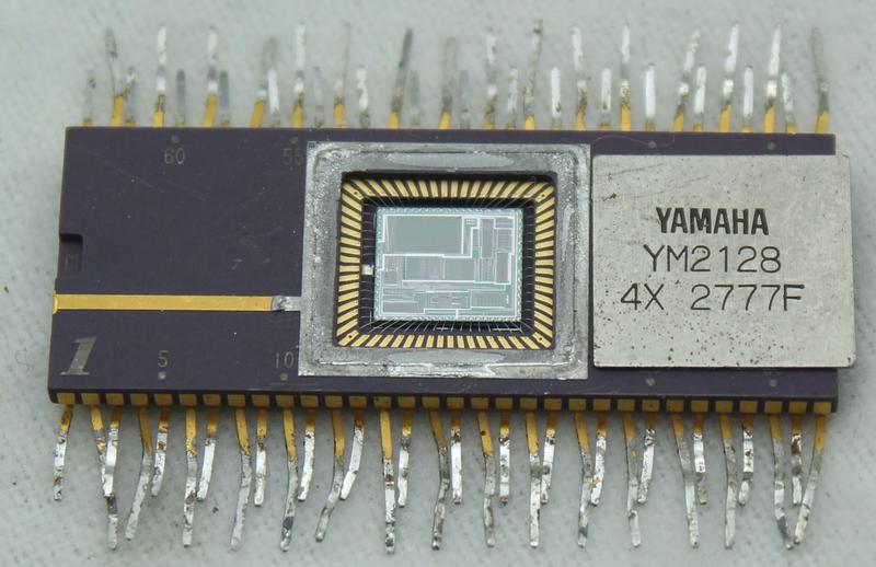
The Yamaha DX7 digital synthesizer was released in 1983 and became extremely popular, defining the sound of 1980s pop music. Because microprocessors weren't fast enough in the early 1980s, the DX7 used two custom digital chips: the EGS "envelope" chip generated frequency and envelope data, which it fed to the OPS "operator" chip that generated the sound waveforms. A key part of the OPS chip is an exponential circuit, which is used for frequency calculation and envelope application. In this blog post, I examine this circuit—implemented by a ROM, shifter, and other circuitry—in detail and extract the ROM's data.
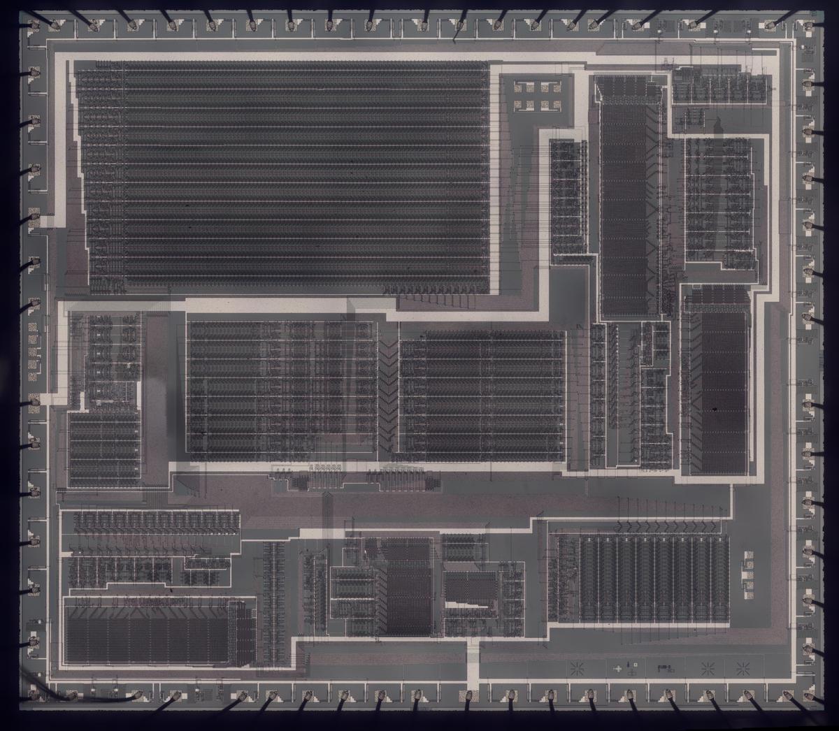
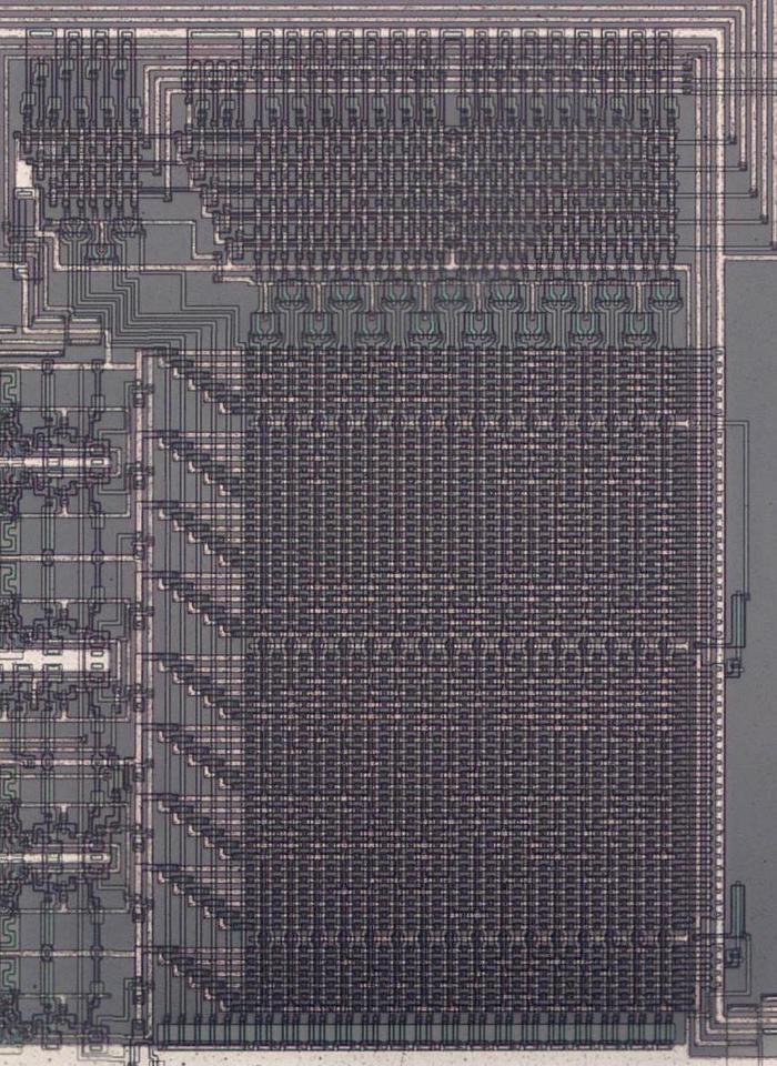
I created the high-resolution die photo below by compositing over a hundred microscope photos. Around the edges, you can see the 64 bond wires attached to pads; these connect the silicon die to the chip's 64 pins. The chip has one layer of metal, visible as the whitish lines on top. (Power and ground are the thick metal lines.) Underneath the metal, the polysilicon wiring layer appears reddish or greenish. Finally, the underlying silicon is grayish. I discussed the chip as a whole in my previous DX7 article; now I will focus on the exponential circuit.
The DX7 was the first commercially successful digital synthesizer. Instead of the analog oscillators and filters of an analog synthesizer, the DX7 generates sounds digitally, using a technique called FM synthesis. The idea is that you start with a sine wave (the carrier signal) and perturb it with another signal (the modulating signal). The modulating signal changes the phase (and thus the frequency) of the carrier, creating complex harmonic structures. These signals are represented as digital values throughout the system; a digital-to-analog converter (DAC) turns the digital representation into an analog voltage for the synthesizer's output.
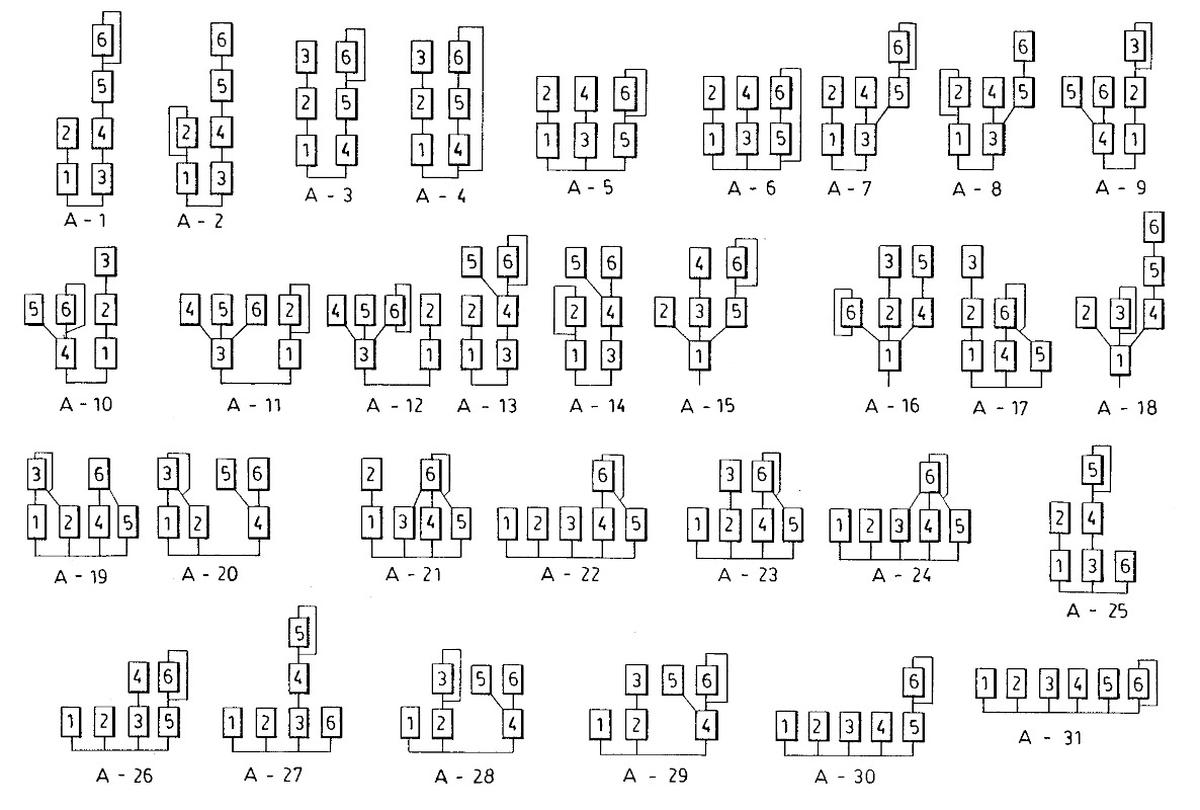
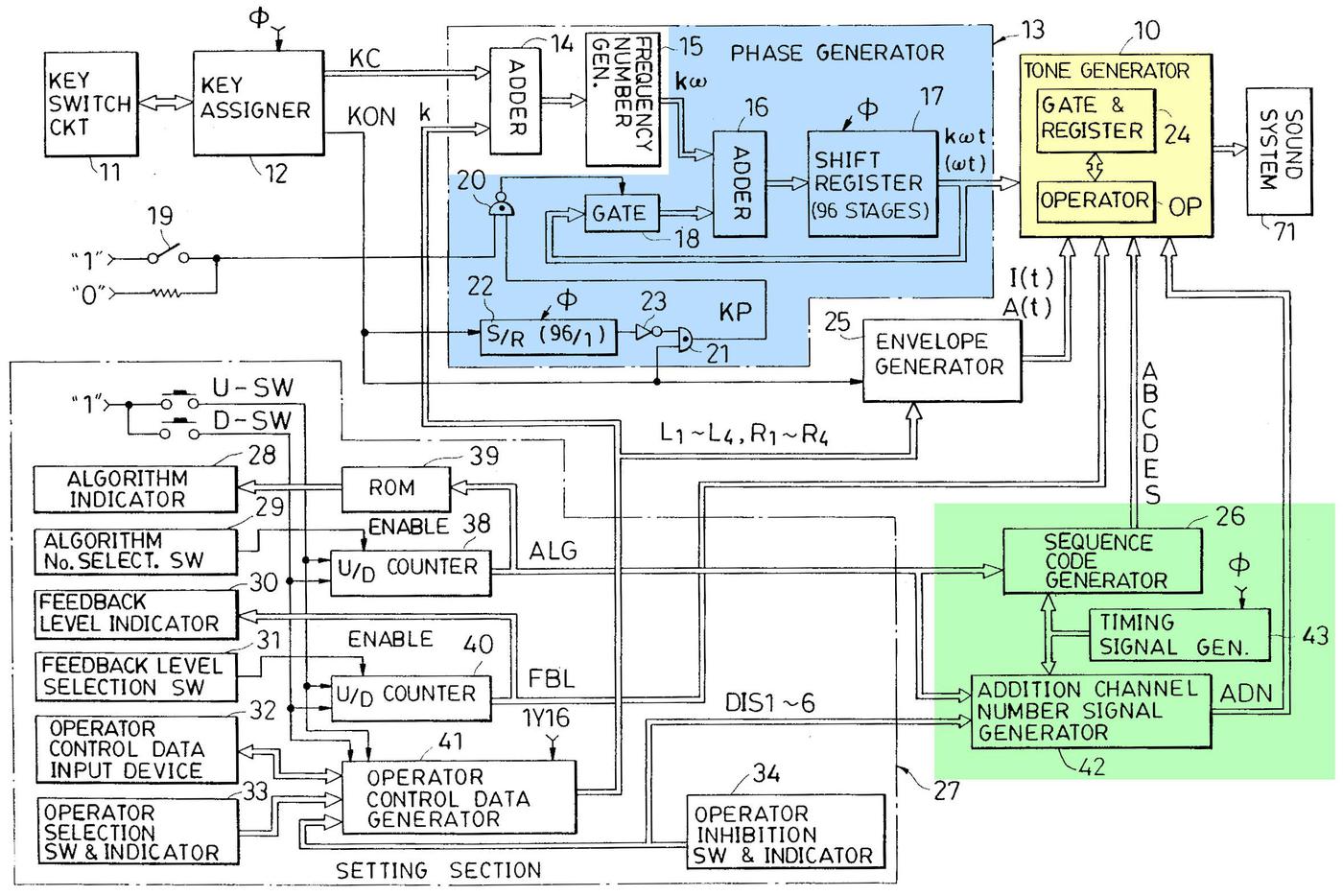
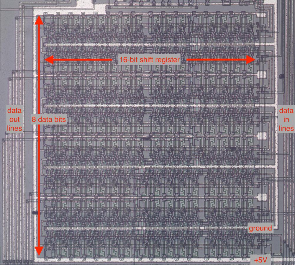
The digital implementation of frequency modulation uses a lookup table that holds a digitized sine wave. By stepping an index through the table at a specific rate, you can produce a sine wave of a fixed frequency. By perturbing this index with another signal, you can produce a modulated sine wave. The DX7 implements this with a sine-wave table in ROM, an increment value that controls the frequency, and an adder that adds the increment to the table index (i.e. the phase angle) each time step. The DX7 has 96 oscillators, so it keeps track of 96 separate phase angles; these are stored in the phase accumulators. The frequency modulation is implemented by operator circuitry, which allows oscillators to perturb other oscillators. (This is a very brief overview of FM synthesis; see my previous DX7 reverse-engineering article for more details.)
Logarithms and exponentials
In hardware, multiplication is much slower than addition, especially with 1980s-era technology. The solution in the DX7 is to represent values as base-2 logarithms because adding logarithms is equivalent to multiplying the values. By applying 2x to the sum, the logarithmic value can be converted back to a linear value.
The first role for logarithms is in the frequency input to the chip: the phase increment value supplied to the chip is logarithmic. The motivation is that note frequencies are related exponentially: for instance, going up one octave doubles the frequency. By using logarithms, note computations can be done with addition.
Second, each oscillator has an associated envelope, which changes the output level according to a time-varying curve.1 To multiply the signal by the envelope level, the sine wave signal and the envelope are both represented logarithmically. Thus, the multiplication is replaced by addition. (The logarithm of the sine-wave signal is conveniently obtained by storing log2(sin(x)) in the waveform ROM instead of sin(x), so the logarithm is obtained "for free".)
The block diagram below shows the structure of the exponential circuit that converts the logarithmic value to a linear value by computing 2x. The exponential circuitry is somewhat complex to fit a fast, high-accuracy exponential calculation into a small space on the die. The circuit takes a 14-bit input value that consists of a 4-bit integer part and 10 fractional bits, so it computes 2x for 0≤x<16.2 The circuit uses a ROM lookup and a shift to rapidly compute the value.
The ROM takes a 10-bit input address (0 through 1023) representing x values 0 through 1023/1024. A technique called delta encoding is used to reduce the size of the ROM. The idea of delta encoding is that if values change slowly, the difference between two values is considerably smaller than the value itself.3 Specifically, only every fourth value is explicitly stored in the ROM; this value is called an "absolute" value.7 The next three values are stored as the deltas, difference between the value and the previous absolute value. The deltas fit into 4 bits4, a considerable saving over the 11-bit absolute values. An adder circuit adds the absolute value to the difference value, yielding the desired exponential value.
The final step in the exponential circuity is to perform a binary shift on the value from the ROM. Shifting by the number of bits in the integer part of the input results in the final exponential value.6 Prior to shifting, a leading 1 is added to the ROM's value so this bit doesn't take up space in the ROM.5 The chip has two exponentiation circuits: one for computing the frequency and one for computing the signal (the sine and envelope path). Most of the circuitry is identical between the two, but the frequency exponent produces 22 bits of output, while the signal exponent has just 14 bits of output.
A closer look at the die
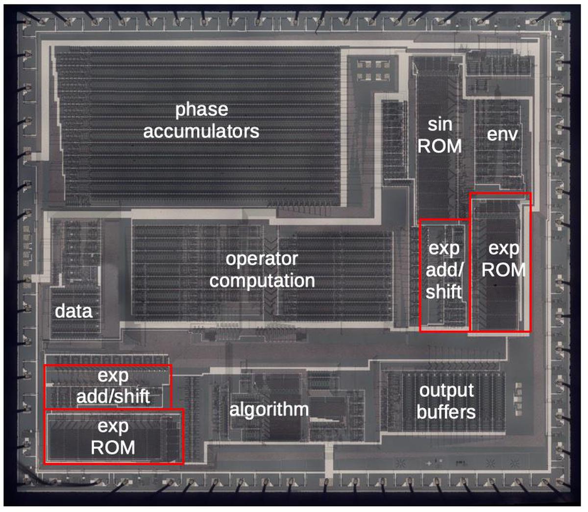
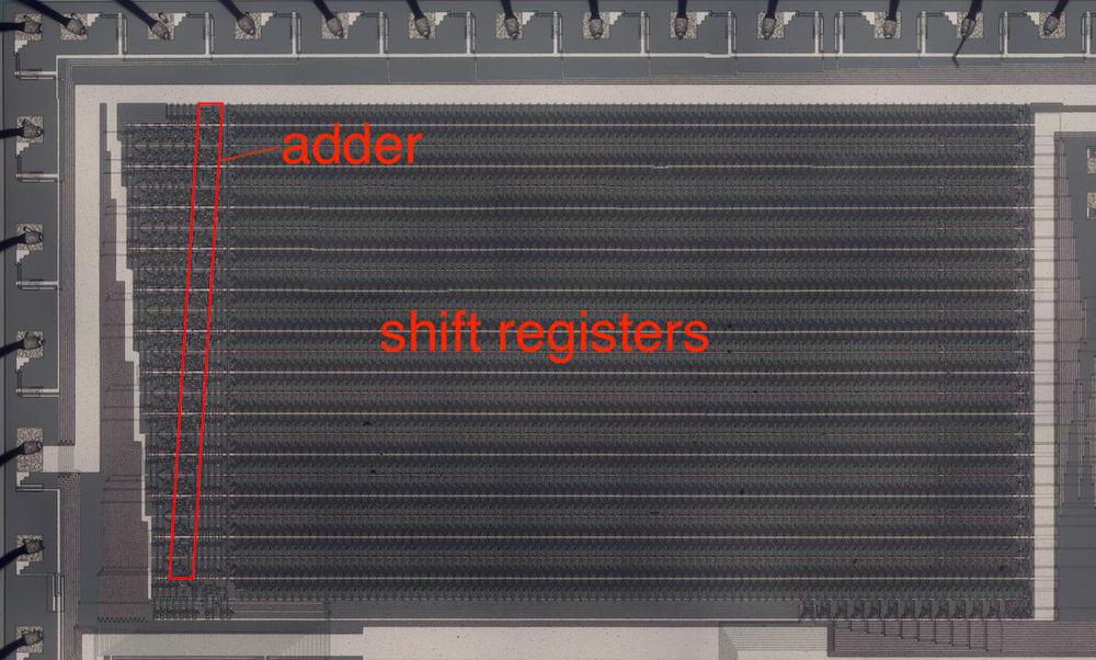
The diagram below labels the pins and the main functional blocks of the chip. In this article, I focus on the two exponential circuits, highlighted in red, but I'll summarize the other blocks. The 96 phase accumulators, implemented with shift registers, are the largest block of the chip. ROMs hold the sine wave function and the exponential function. (There are two identical exponential ROMs, with associated adder and shifter circuitry.) Other major blocks apply the envelope, hold configuration data, compute the operators that combine oscillators, define different operator algorithms, and buffer the output values.
Transistors
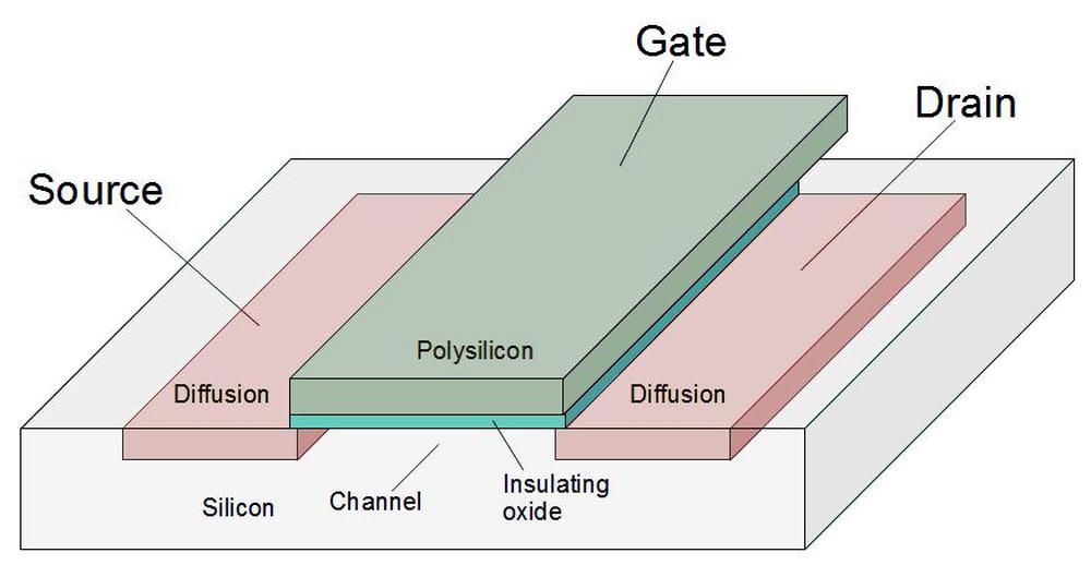
To explain the die photos, I'll first show how a transistor (below) is constructed in an NMOS integrated circuit. Regions of the silicon are doped with impurities to create diffusion regions with desired properties. The transistor can be viewed as a switch, allowing current to flow between two diffusion regions called the source and drain. The transistor is controlled by the gate, made of a special type of silicon called polysilicon. A high voltage on the gate lets current flow between the source and drain, while a low voltage blocks current flow. These tiny transistors are combined to form logic gates and other circuits.
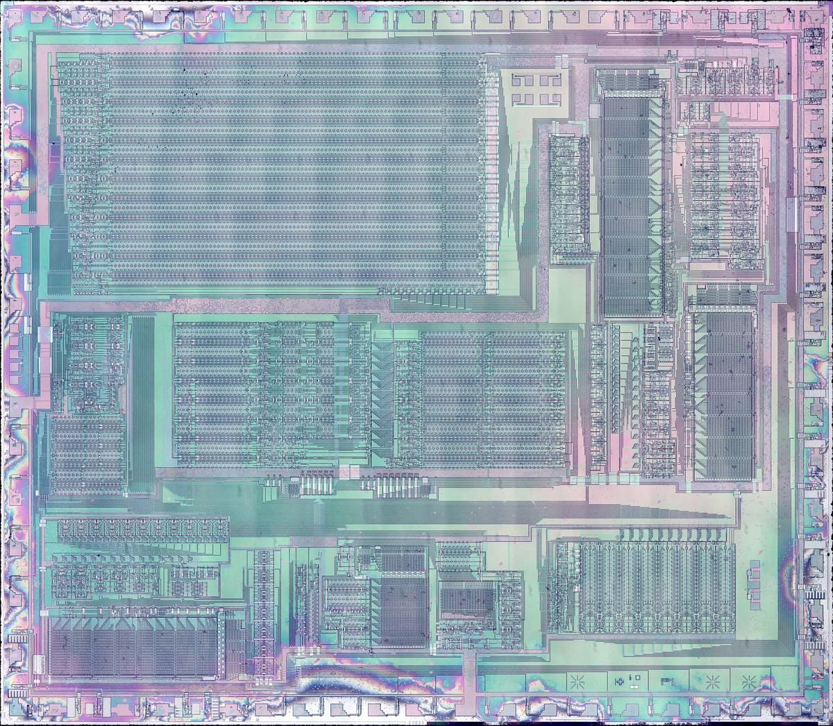
To make the transistors more visible, I removed the metal layer from the chip, resulting in the high-resolution die photo below. (The colors are due to variations in the thickness of the oxide layer due to my etching process.)
The ROM
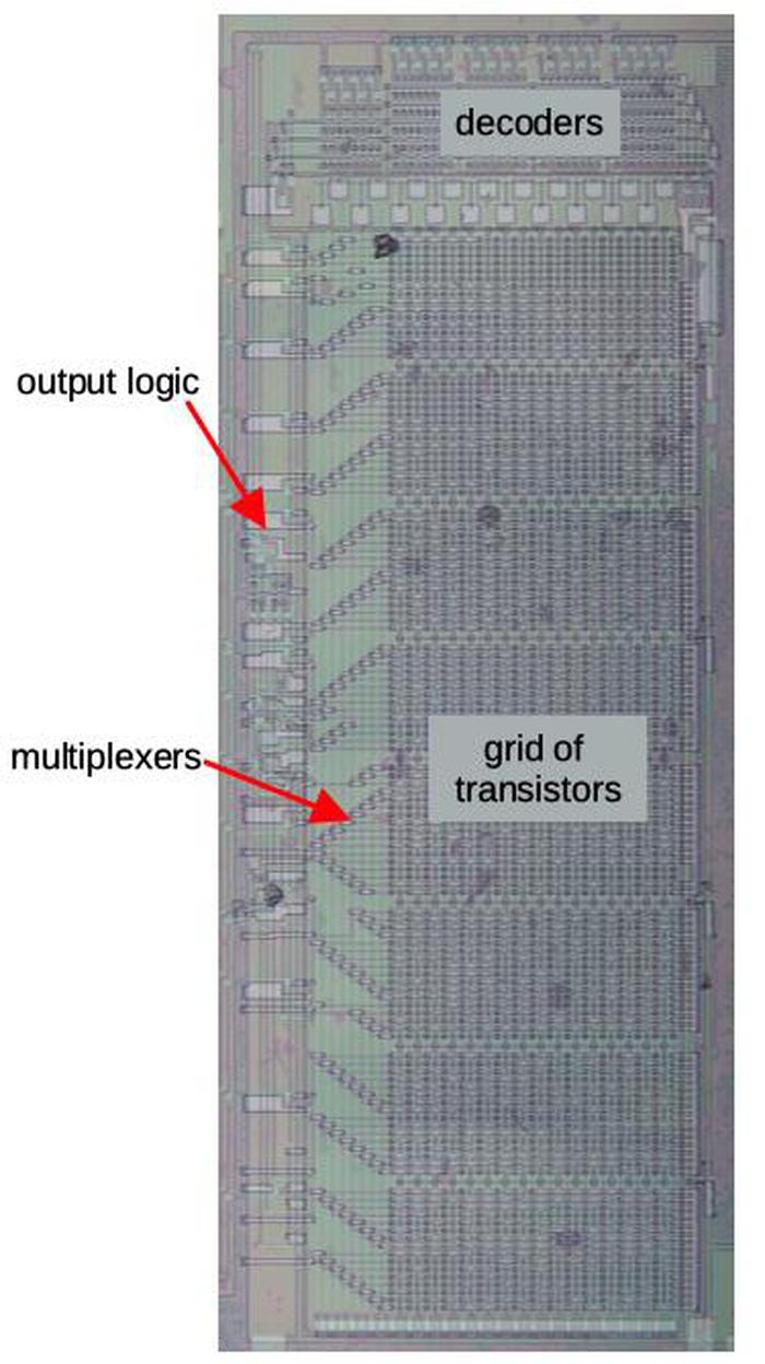
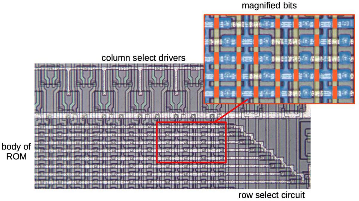
The diagram below shows one of the exponential ROMs. The ROM is constructed from a grid of transistors: 128 rows by 32 columns.8 At each grid point, a transistor can be present, representing a 1 bit; or a transistor can be absent, representing a 0 bit.9
At the top, decoders activate one of the 32 vertical select lines in the ROM, based on five bits of the address. The ROM is arranged into groups of 8 rows (or fewer, depending on compression). A multiplexer selects one bit of each group, based on three bits of the address. This produces a 20-bit output. Finally, the output logic produces the desired delta value, based on the address. The result is the 11-bit absolute value and a 4-bit delta value.
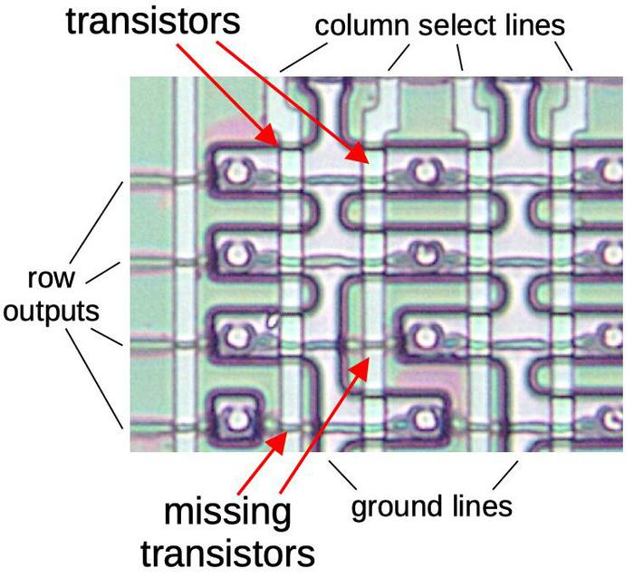
Zooming in on the ROM shows the individual transistors. The large pale regions are the doped silicon, forming transistor sources and drains. The polysilicon select lines are vertical. A transistor is formed when a polysilicon line crosses a doped silicon region. The indicated silicon regions are connected to ground, pulling one side of each transistor low. The circles are connections called vias between the silicon and the metal lines above. (The metal lines have been removed but the wavy horizontal lines show where the metal was.)
Each bit is stored in the ROM by the presence or absence of a transistor at a grid position. (During manufacturing, the silicon doping pattern controls whether or not a transistor exists.) When one of the 32 select lines is activated, all the transistors in that column will turn on, pulling the corresponding output lines low. But if a transistor is missing, the corresponding output line will remain high. Thus, a value is read from the ROM by activating a select line, reading that ROM value onto the output lines. By looking at the silicon pattern in the ROM, I determined the sequence of 1's and 0's stored in the ROM, 4 kilobits in total.
The multiplexer
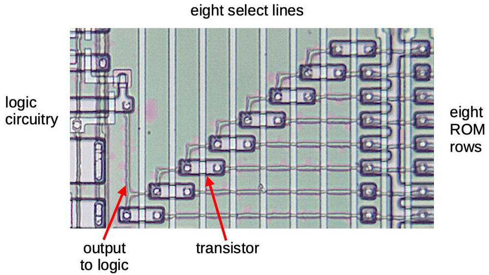
The ROM has 256 entries of 20 bits, before the delta processing is applied. To make the layout more efficient, the ROM stores bits in groups of 8, (conceptually) organized as 8 rows of 32 entries (columns) for each output bit. Each output bit has a multiplexer that selects one of the 8 bits in the group, based on 3 more address lines that control the 8 multiplexer select lines.
Each multiplexer (above) is implemented by 8 pass transistors. One transistor is activated, letting that row's bit through, while the unselected rows are blocked. The output of the multiplexer goes to the logic circuitry on the left.
Looking at the die photo closely shows that some of the multiplexers don't have all eight rows. This is a key optimization to reduce the ROM size. If all the bits in a row are 0, the row can be eliminated from the ROM entirely.10
The delta logic and the adder
The ROM produces 20 output bits, 11 bits for the "absolute" value and 9 bits for the three delta values. Some logic circuitry expands the ROM's 9 bits into three deltas of four bits, taking advantage of some structure in the deltas.11
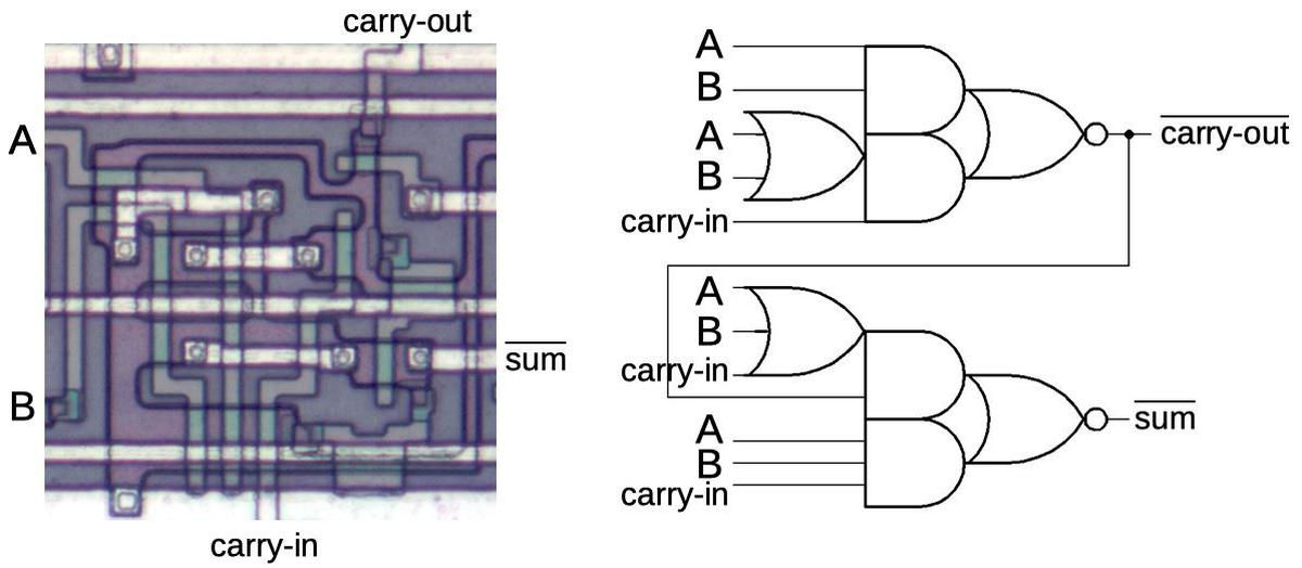
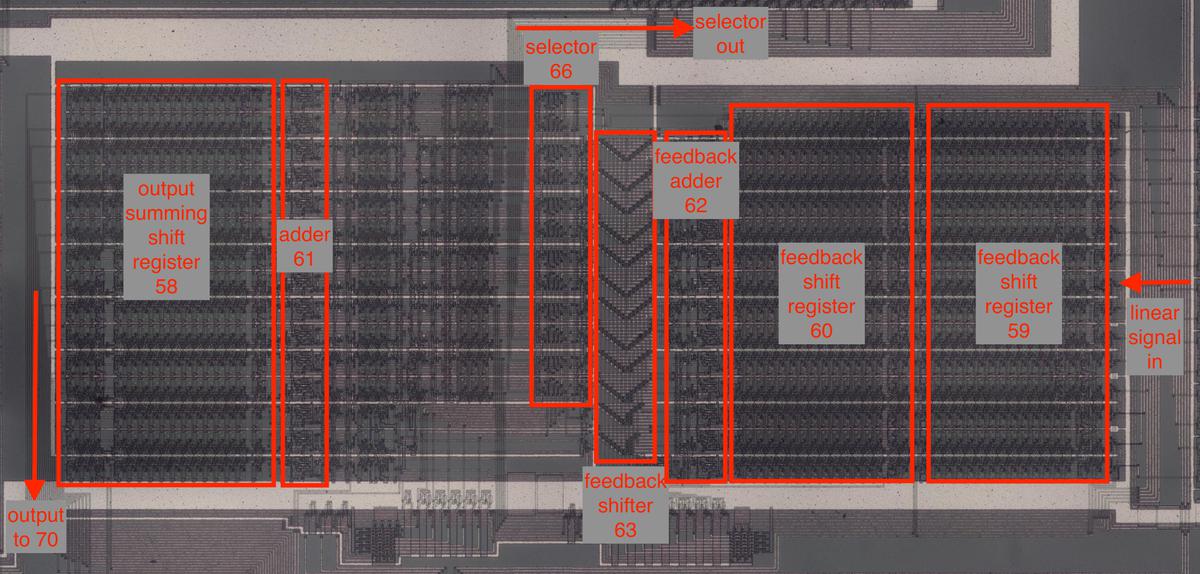
To obtain the 2x-1 value, the 11-bit absolute value and the 4-bit delta must be added. This is accomplished by an adder circuit to the left of the ROM. One interesting feature of the adder is it is pipelined to minimize the delay from carry propagation. I discussed the adder in my previous article so I won't go into details here.
The bit shifter
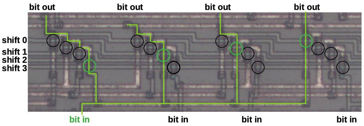
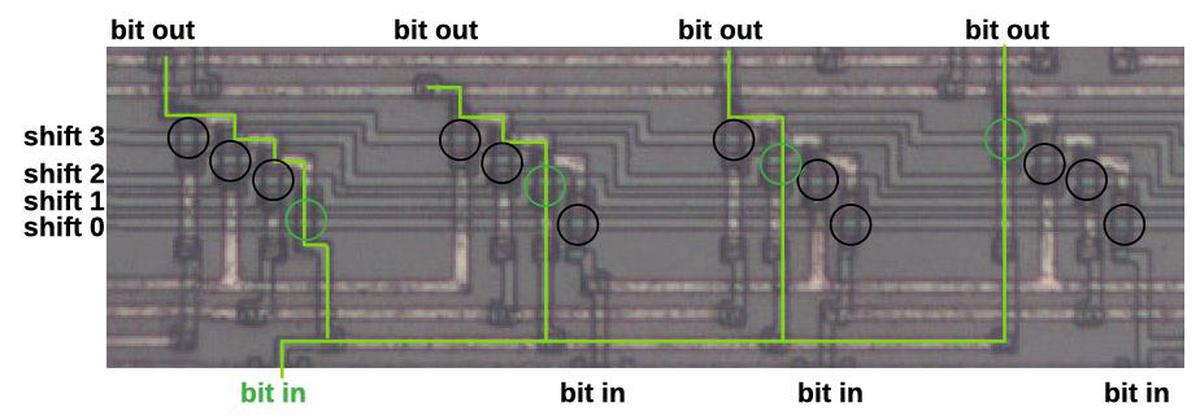
The final building block that I'll discuss is the bit shifter, which implements the integer part of the exponential calculation. It shifts the value to the left by 0 to 15 bits, which is equivalent to multiplying by a power of 2. The shifter is built in two layers: the bottom layer shifts by 0, 1, 2, or 3 positions. The upper layer shifts by 0, 4, 8, or 12 positions. The combination of the two layers permits any shift between 0 and 15 bit positions. Wiring between the two layers distributes the outputs from the first layer to the second layer. Each output goes to four inputs, each spaced 4 bits apart to provide the larger shift.
The diagram below shows part of the shifter that shifts by 0, 1, 2, or 3 positions, controlled by the horizontal lines. The shifter is built from multiplexers, similar to those in the ROM, that select one of four inputs. I've highlighted one of the bits in green. If the "shift 0" line is activated, the rightmost green transistor (circled) will turn on and the green input bit will exit from the rightmost output. Likewise, if the "shift 1" line is activated, the second green transistor will turn on and the green bit will exit shifted one position to the left. The "shift 2" and "shift 3" lines will cause the green bit to be shifted two or three positions to the left. The remaining transistors (circled in black) act in the same manner to shift the other bits. The result is that all the bits will be shifted by shifted 0, 1, 2, or 3 positions. The second shifter is similar, except the input lines go to multiplexers that are four positions apart.
Conclusion
Computing exponents is a key part of the DX7's sound synthesis. The chip needs to compute exponents very quickly, faster than an algorithm such as CORDIC could operate, but a straightforward ROM would have been much too large. The chip solves this dilemma by using delta encoding, ROM compression, and a shifter circuit. These techniques reduced the ROM size by almost 64%.12 By examining the circuitry closely, I have reverse-engineered the exact values that are generated. DX7 emulators may be able to achieve more accuracy by using these values.
The next step is to reverse-engineer the chip's sine wave ROM, which implements the log-sin function. That ROM uses many of the same techniques as the exponential ROM, but stores the deltas differently, for instance. I announce my latest blog posts on Twitter, so follow me @kenshirriff for updates. I also have an RSS feed. If you're interested in ROM data, I also wrote about extracting constants from the 8087 floating point chip.
Thanks to Jacques Mattheij and Anthony Richardson for providing the chip and discussion.14
Notes and references
-
For an output signal, the envelope gives the note a more realistic sound; a typical sound has a sharp attack when it is first played, and then the volume decays. The level is sustained until the key is released, and then dies off quickly. However, the DX7 also applies envelopes to the modulating signals, allowing the timbre of the note to change over time. ↩
-
The exact values of the exponentiation circuit are given as follows. Suppose the 14-bit input value is int.frac, where int is the 4-bit integer part and frac is the 10-bit fractional part. The 12-bit output value from the ROM, after the delta adder and appending a leading 1 bit, is exactly given by round(2frac×2048). The shifter applies a left shift of 0 to 15 bits and then the result is truncated to 22 or 14 bits, for the frequency and signal exponentiation respectively. The final results are
round(2frac× 2048) << int >> 5, and
round(2frac× 2048) << int >> 13, respectively
(where << and >> are the bit shift operators).In both cases, the fixed 1 is in the leftmost position of the output when the input has maximum integer portion (i.e. 15). (This is necessary since otherwise the value would either get truncated, or the leftmost bit would be unused.) However, with input integer portion of 0, the frequency circuit still has 7 bits of output, while the envelope circuit produces a value of 0 (since all the bits are lost in shifting). ↩
-
A different chip, the Yamaha YMF262 was used in computer sound cards such as the Sound Blaster 16. (This chip is also known as OPL3 for FM Operator Type-L.) It uses FM synthesis, but is stripped down compared to the DX-7. The chip was reverse-engineered by Matthew Gambrell and Olli Niemitalo who decapsulated the chip and read out the ROM contents.
The OPL3 exponential ROM is similar to the DX7's in some ways, but is also very different. The OPL3 chip is 256 samples long, rather than 1024, and holds 10-bit values, rather than 12-bit values. Both chips use delta encoding, but the OPL3 has one delta-encoded value for each absolute value, while the DX7 has three delta-encoded values. ↩
-
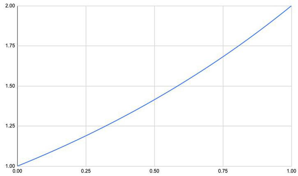
The graph below shows the exponential function 2x over the fractional range. The difference between successive elements is fairly small, so a 4-bit delta value is sufficient. Storing a 4-bit difference instead of an 11-bit absolute value achieves a large space saving.
Graph of 2x over the fractional range.Since the exponential function is convex, the largest delta in the exponential table is at the right, specifically (21023/1024-21020/1024)×2048 ≈ 8.3. The delta almost fits into three bits, but four bits are required. ↩
-
The ROM stores 2x-1 rather than 2x, since all the values have a leading one. Specifically, for 0≤x<1, 1≤2x<2. Adding 1 to the ROM's output instead of explicitly storing it in the ROM reduces the ROM's size. ↩
-
Mathematically, if the input value is split into integer and fractional parts: int+frac, then 2int+frac = 2int×2frac. Multiplying by 2int is the same as performing a binary shift int bits to the left. ↩
-
The absolute value in delta encoding is the full, explicit value. It's unrelated to the absolute value function |x|. ↩
-
The two exponential ROMs on the chip are identical, except one is horizontal and one is vertical. This makes referring to rows and columns a bit ambiguous; hopefully it all makes sense. ↩
-
Whether a transistor in the ROM represents a 1 or a 0 is somewhat arbitrary, since the signal gets inverted several times before use. A transistor will cause that line of the ROM to be pulled low, so at the fundamental level a transistor represents a 0. However, in the exponential ROM, this value is immediately inverted, so a transistor represents a 1 bit in the final result. ↩
-
The ROM operates in two phases, controlled by the clock. In the first phase, the rows and the multiplexers are all pulled high. In the second phase, the desired ROM column is activated. If there are transistors, they will pull the rows low. Through the selected multiplexer transistor, this will pull the multiplexer low. The multiplexer output is then inverted, so a position with a transistor represents a logical 1 and the absence of a transistor represents a logical 0. With this circuit, if a row and multiplexer transistor are omitted entirely, the multiplexer will retain its high precharge value, which represents a logical 0. Thus, any rows in the ROM that are all 0 can be eliminated, saving space. ↩
-
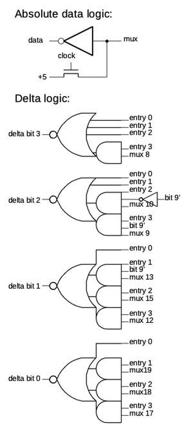
The schematic below shows the implementation of the logic to produce the absolute data and the deltas. The 11 absolute data bits simply take the corresponding multiplexer output and invert it. Each multiplexer also has a transistor to precharge it to +5 on the clock phase 1. (The delta multiplexers also have precharge transistors, but I omitted them from the schematic to avoid clutter.)
Diagram of the logic circuitry.The delta bit logic implements four different cases. Entry 0 provides a delta value of 0 for the absolute value. It is followed by three entries for the values stored as deltas. (In all four cases, the value is computed by adding the absolute value and the delta.) The two low-order address bits select the entry. If the 9 bits from the ROM are labeled A-I, the successive 4-bit delta entries are 0000 (no delta for the "absolute" value), 00AB, 0CDE, FGHI. Three entries use the top bit of the address (bit 9) to force a delta bit to 1 over half the range. This is another optimization so those regions don't need to be stored in the ROM. ↩
-
The exponential circuit takes a 14-bit input and produces a 22-bit output. Holding all these values in a ROM would take over 360 kilobits, impractical in the 1980s. The use of a shifter dramatically reduced the storage requirement to 1024 11-bit values (11 Kb). The ROM compression techniques reduced this to just 4 kilobits, almost 64% less. In this section I break down how the ROM compression is implemented.
The majority of the savings comes from the delta encoding, which uses 256 11-bit "absolute" values and 768 4-bit delta values. This reduces the storage to about 5.9 Kb, saving about 48%. The remainder of the savings comes from eliminating rows in the ROM through various techniques. The ROM is structured as rows of 32 bits. Uncompressed, the ROM would require 184 rows. However, if the values in a row are all 0, the row can be omitted entirely, due to the multiplexer's construction.13 Since the exponential curve grows slowly, the top bits of the absolute value are 0 for large stretches, so many rows can be eliminated. Specifically, the topmost bit is zero for 4 of 8 rows, the next bit zero for 3 of 8 rows, and the next bit zero for 1 row. Thus, 8 rows can be eliminated for the absolute value storage.
The delta bits are also zero much of the time. The top two bits of the first delta are always 0, as is the top bit of the second delta. This is handled by the logic circuitry, eliminating 24 rows of the ROM. 12 more zero rows are eliminated from delta bits that are zero some of the time. Finally, the logic circuitry forces 3 delta bits to 1 over half-intervals where they are always 1, making 12 more rows unnecessary.
To summarize, zero-row-elimination saves 8 rows from absolute value data, and 36 rows from delta data. Another 12 rows are saved by forcing bits to 1. This reduces the ROM from potentially 188 rows to the 128 rows it has, shrinking it almost 32%. ↩
-
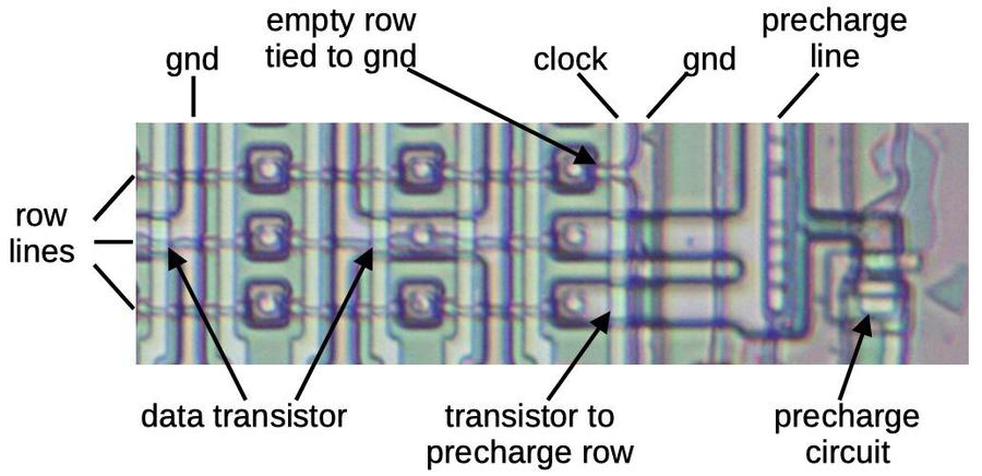
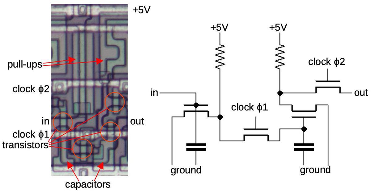
Conceptually, rows in the ROM can be considered NOR gates with pull-up resistors. However, the implementation is slightly different: rows are precharged to +5 during one clock phase and then discharged (or not) to ground through transistors. This reduces the power consumption compared to regular NMOS pull-ups. (Modern circuits use CMOS instead of NMOS to avoid the static power consumption of pull-ups.)
The ROM with its precharge circuit. This is a bit tricky to interpret. The row lines are metal as is the ground line on the right. The other ground lines and the precharge line are in silicon. The clock and the column select lines (unlabeled) are in polysilicon.Another optimization is that rows in the ROM that are all 1's have the transistors omitted and the output line connected directly to ground. This reduces power consumption slightly, since that row line won't be charged and discharged. However, it doesn't save any space, since the row is still physically present. (In contrast rows that are all 0's are omitted entirely.) ↩
-
For more information on the DX7 internals, see DX7 Technical Analysis, DX7 Hardware, OPLx decapsulated, and my previous DX7 article Reverse-engineering the Yamaha DX7 synthesizer's sound chip from die photos. ↩
