In this article I describe repairing an IBM 029 keypunch that wouldn't punch numbers. Keypunches were a vital component of punch card computing, recording data as holes in an 80-column card. Although keypunches have a long history, dating back to the use of punch cards in the 1890s, the IBM 029 keypunch is slightly more modern, introduced in 1964. The repair turned out to be simple, but in the process I learned about the complex mechanical process keypunches used to encode characters.
 rather than the character. Compare with the photo of a different 029 keyboard later.")
A couple weeks ago, I was using the 029 keypunch in the Computer History Museum's 1401 demo room and I found that numbers weren't punching correctly. The keyboard has a "Numeric" key that you press to punch a number or special character. (Unlike modern keyboards with a row of numbers at the top, numbers on the 029 keyboard share keys with letters.) When I tried to type a number, I got the corresponding letter; the keypunch was ignoring the "Numeric" key. The same happened with special characters that required "Numeric".
Frank King, an expert on repairing vintage IBM computers, showed me how to fix the keyboard. The first step was to remove the keyboard from the desk. This was surprisingly easy—you just rotate the keyboard clockwise and lift it up.

On the underside of the keyboard are several microswitches for some special function keys. The microswitches are on the left half, connected by blue wires. Also note the metal rectangles along the right; these are the "latch contacts", one for each key and will be discussed later.

Frank noticed that the keystem for the "Numeric" key wasn't pressing the microswitch, but was out of alignment and missing the microswitch's lever entirely. Thus, pressing the "Numeric" key had no effect and the wrong character was getting punched. He simply rotated the microswitch slightly so it was back into alignment with the keystem, fixing the problem. We placed the keyboard back into the desk and the keypunch was back in business. Many vintage computer repairs are difficult, but this one was quick and easy.
How the keypunch encodes characters
This repair was a good opportunity to look inside the keyboard and study the interesting techniques it uses to encode characters. On a punch card, each character is indicated by the holes punched in one of the card's 80 columns, as shown below. The digits 0 through 9 simply result in a punch in row 0 through 9. Letters are indicated by a punch in digit rows 1 through 9 combined with a punch in one of the top three rows (the "zone" rows1). Special characters usually use three punches. Since each character can have punches in any of 12 rows, you can think of cards as using a (mostly-sparse) 12-bit encoding.

Since each key on the keyboard has one character in alpha mode and another character in numeric mode, the keypunch must somehow determine the hole pattern for each character. With modern technology, you could simply use a tiny ROM to hold a 12-bit row value for the "alpha" mode and a second 12-bit value for the "numeric" mode. (Or use a keyboard encoding chip, digital logic, a microcontroller, etc.) But back in the keypunch era, ROMs weren't available. Instead, the keypunch uses a complex but clever mechanical technique to assign a hole pattern to each character.
The previous model: the 026 keypunch
.")
Before explaining how the 029 keypunch encodes characters, I'll discuss the earlier and simpler IBM 026 keypunch, which was introduced in July 1949. The 026 used the technology of the 1940s: vacuum tubes and electromechanical relays. Encoding the hole pattern with tubes or relays would be bulky and expensive. Instead, the keypunch used a mechanical encoder with metal tabs to indicate where to punch holes.

The diagram above shows the keyboard mechanism in the keypunch. The basic idea is there are 12 "bail contacts" (one for each row on the card); when you press a key, the appropriate contacts are closed to punch holes in the desired rows. To implement this, each key was connected to a separate vertical "permutation bar" by a "latch pull-bar". When a key is pressed, the associated permutation bar drops down. Twelve horizontal bars, called "bails",2 ran perpendicular to the permutation bars, one bail for each row on the card. At each point where a bail crossed a key's permutation bar, the bail could have a protruding tab that meshes with the permutation bar. Pressing a key would cause the permutation bar to push the tab and rotate the bail, closing the bail contact and punching a hole in that row. Thus, the 12 bails mechanically encoded the mapping from keys to holes by the presence or absence of metal tabs along their length.

The photo above shows a permutation bar (right) engaging four tabs on the bails (left). In the photo below, you can see one of the bails removed from the keyboard mechanism. Note the tabs extending from the bail to engage with the permutation bars. Also note the contact on the left end of the bail.

There is a problem with this 12-bail mechanism: it only handles a single character per key, so it doesn't handle numbers. (The keyboard diagram below shows how numbers share keys with letters.) The obvious solution is to add 12 more bails for the second character on a key, but this would double the cost of the mechanism. However, since numbers are indicated by a single punch in a column, a shortcut is possible: use a switch on each number key to punch that row. The 026 keypunch does this, using the latch contacts shown in the earlier diagram. In numeric mode, the latch contact for the "1" key would punch row 1, and so forth for the other numbers. To handle the special characters, three additional bails were added, bringing the total number of bails to 15.5 Thus, the 026 had 12 bails used in alpha mode, 3 bails used in numeric mode for special characters, and a latch contact for each key for numbers and special characters.

The permutation bar and bail mechanism also explains why the "Numeric" key (the one we fixed) has a separate microswitch under the keyboard. The regular mechanism with permutation bars, bails and latch contacts only allows one key to be pressed at a time.3 Since "Numeric" is held down while another key is pressed, it needed a separate mechanism.4
Back to the 029 keypunch
When the 029 keypunch was introduced in 1964, it replaced the 026's vacuum tubes with transistorized circuitry and updated the keypunch's appearance from 1940's streamlining to a modernist design. However, the 029 kept most of the earlier keypunch's internal mechanical components, along with many relays.6

A major functional improvement over the 026 was the addition of many more special characters in the 029; almost every key on the keyboard had a special character. The three numeric mode bails used in the 026 couldn't support all these special characters. The obvious solution would be to add more bails; with 12 bails for alpha and 12 bails for numeric, any characters could be encoded. But, IBM came up with a solution for the 029 that supported the new special characters while still using the 026's 15-bail mechanical encoder. The trick was to assign the bails to rows in a way that handled most of the holes, leaving the latch contact to handle one additional "extra" hole per key.7
The diagram below shows part of the encoding mechanism, based on the keypunch schematics.8 Horizontal lines correspond to the 15 bails; the labels on the left show the row handled by each bail. Each vertical line represents the permutation bar for a key; the key labels are at the bottom. The black dots correspond to tabs on the bail, causing the bail to tripped when activated by the corresponding key. (The circles symbolize the interlock disks that keep two keys from being used simultaneously.3) Note that the 029's bails don't handle all the rows for alpha mode (unlike the 026), leaving some alpha holes to be punched by the latch contacts.

The yellow highlights on the diagram show what happens for the "W _" key. Pressing this key (bottom) will activate the "Numeric 5", "Numeric 8" and "Common 0" bails (left). In addition, the latch contact will activate "Alpha 6" (top). Putting this together, in alpha mode, rows 0 and 6 will be punched and in numeric mode, rows 0, 8 and 5 will be punched. These are the codes for "W" and "_" respectively, so the right holes get punched. The encoder works similarly for other keys, punching the appropriate holes in alpha and numeric modes. Thus, the 029 managed to extend the 026's character set with many new special characters, without requiring a redesign of the mechanical encoder.

Conclusion
For once, repairing computer equipment from the 1960s was quick and easy. Fixing the "Numeric" key didn't even require any tools. The repair did reveal the interesting mechanism used to determine which holes to punch. In the era before inexpensive ROMs, keyboard decoding was done mechanically, with tabs on metal bars indicating which holes to punch. This mechanism was inherited from the earlier 026 keypunch (1949), improved on the 029 keypunch (1964) to handle more symbols, and was finally replaced by electronic encoding when the 129 keypunch was introduced in 1971.6
Follow me on Twitter or RSS to find out about my latest blog posts.
Notes and references
-
The card's zone rows are called 12 (on top) and 11 (below 12). Confusingly, sometimes the 0 row acts as a zone (for a letter) and sometime it acts as a digit (for a number). Also note the special characters that use 8 combined with a digit from 2 to 7; essentially this corresponds to a binary value from 10 to 15. The combination of a zone punch and digit punches encoded a 6-bit character. ↩
-
"Bail" may seem like an obscure word in this context, but it's essentially a metal bar. Looking at old patents, in the early 1900s "bail" was most often used to denote a wire handle on a bucket or pot. It then got generalized to a metal bar in various mechanism, especially one that could be lifted up. If you're from the typewriter era, you might remember the "paper bail", the bar that holds the paper down. (Dictionary link.) ↩
-
An interesting mechanism ensures that only one key can be pressed at a time. The keyboard mechanism contains a row of "interlock disks". When a key is pressed the latch bar slides between two of these disks. These disks slide all the other disks over, blocking the path of any other key's latch bar until the first key is released. ↩
-
The other special keys that use a microswitch are "Error reset", "Multi punch", "Dup", "Feed", "Prog 1", "Prog 2" and "Alpha". ↩
-
The 026 keypunch used a clever trick for some of the special characters. Note the four special character keys in the upper left. These characters were carefully assigned so each pair has the same punch except the upper one punches a 3 and the lower punches a 4. Thus, a single encoding worked for the key with the addition of a relay to switch between 3 and 4. ↩
-
In 1964 IBM introduced the IBM 360 line of computers. They were built from hybrid SLT (Solid Logic Technology) modules, an alternative to integrated circuits. Although the IBM 029 keypunch was introduced along with the SLT-based IBM 360, the keypunch used older transistorized SMS boards. Even though the 029 got rid of the 026's vacuum tubes, it was still a generation behind in technology. It wasn't until the 129 keypunch was announced in 1971 (along with the 370 computer line) that keypunches moved to SLT technology.
The 129's keyboard kept much of the mechanical structure of the older keypunches (the permutation bars and latch contacts), but got rid of the bails used to encode the keypresses. Instead, encoding in the 129 was done through digital logic SLT modules (mostly AND-OR gates) controlled by the latch contact switches. The 026 and 029 keypunches originally had model numbers 26 and 29, but with the introduction of the 129, their names were retconned to the 026 and 029. ↩
-
It's not easy to design a keyboard layout that works with the 029 mechanism since the latch contact can support at most one "extra" hole per key, a hole not handled by the bails. The special characters needed to be assigned to keys in a way that would work; this probably explains the semi-random locations of the special characters on the keyboard. For instance, "(" is on "N" while ")" is on "E". Since both ")" and "E" require a hole in row 5, it made sense to put them on the same key, so the latch contact can handle the 5 punch for both. ↩
-
If you want to learn more about keypunch internals, the manuals are on bitsavers.org. In particular, see the Reference Manual, Maintenance Manual and Schematics. ↩


.")
")


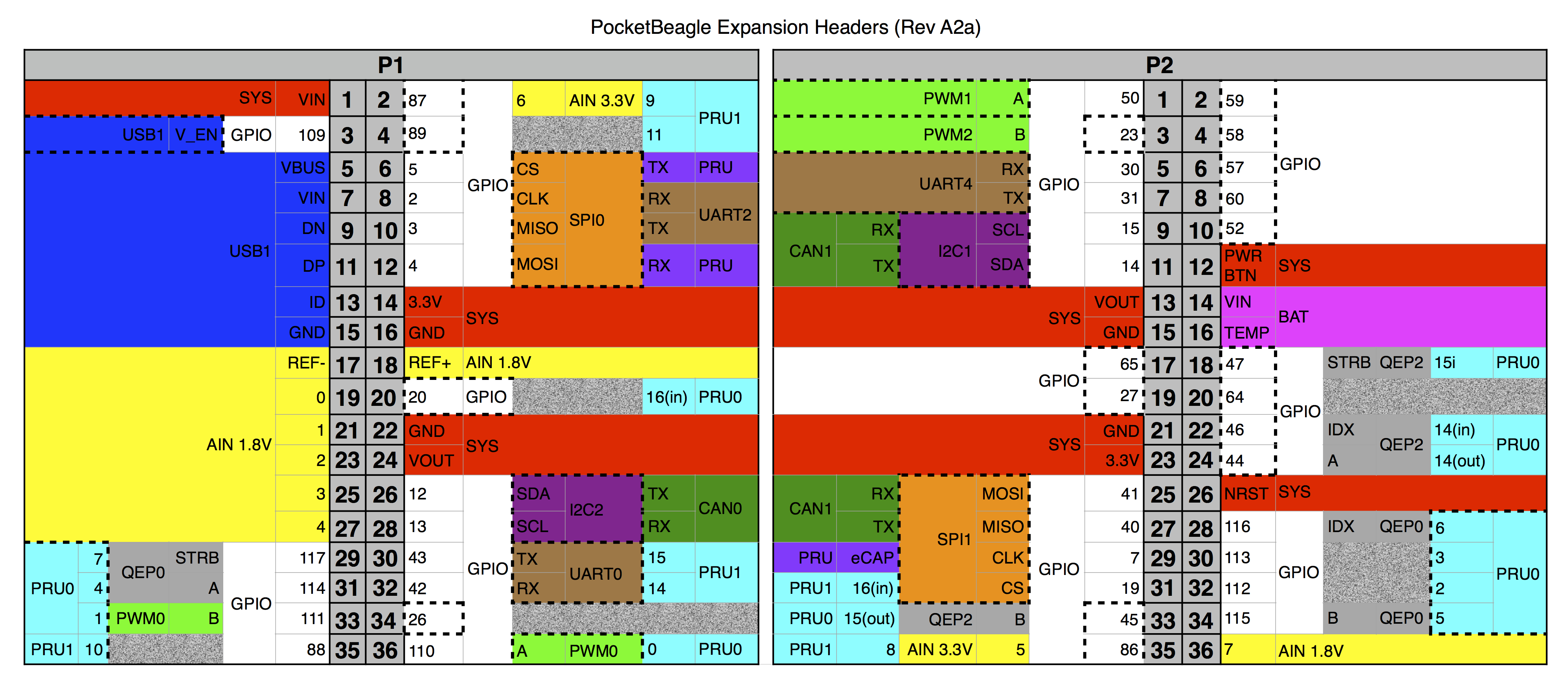
 to the PocketBeagle.")

 can be connected to the PocketBeagle's I2C port with four wires.")

 and printed resistors wired together, an alternative to integrated circuits.")


 is dropped.")

, edges of the Ethernet input (yellow) and the R-C filtered input (green).")


