I'm helping restore a Xerox Alto — a legendary minicomputer from 1973 that helped set the direction for personal computing. This post describes how we cleaned and restored the disk drive and then powered up the system. Spoiler: the drive runs but the system doesn't boot yet.
While creating the Alto, Xerox PARC invented much of the modern personal computer: everything from Ethernet and the laser printer to WYSIWYG editors with high-quality fonts. Getting this revolutionary system running again is a big effort but fortunately I'm working with a strong team: Marc Verdiell, Luca Severini, Ron Crane, Carl Claunch and Ed Thelen, along with special guest Tim Curley from PARC.
If this article gives you deja vu, you probably saw Marc's restoration video (above) on Hacker News last week or read the earlier restoration updates: introduction, day 1, day 2.
Hard disk technology of the 1970s
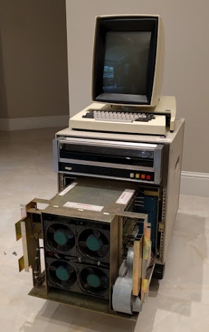
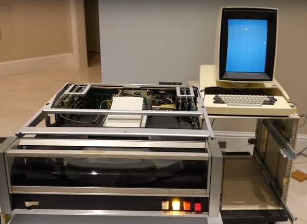
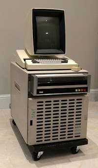
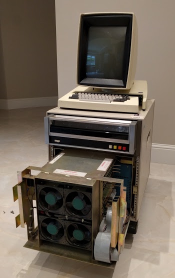
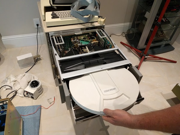
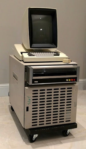
For mass storage, the Alto uses a Diablo disk drive, which stores 2.5 megabytes on a removable 14 inch disk cartridge. With 1970s technology, you don't get much storage even on an inconveniently large disk, so Alto users were constantly short of disk space. The photo below shows the Xerox Alto, with the computer chassis (bottom) partially removed. Above the chassis and below the keyboard is the Diablo disk drive, which is the focus of this article.
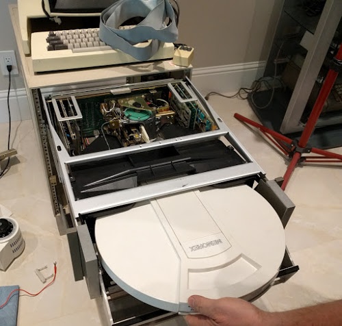
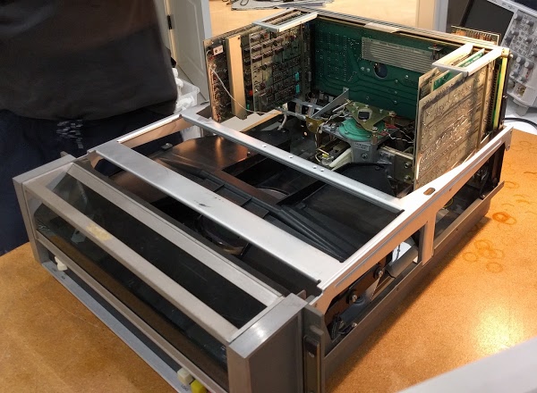
To insert the disk cartridge into the drive, the front of the drive swings down and the cartridge slides into place. The cartridge is an IBM 2315 disk pack, which was used by many manufacturers of the era such as DEC and HP, and contains a single platter inside the hard white protective case. The disk drive has been partially pulled out of the cabinet and the top removed, revealing the internals of the drive. During normal use, the disk drive is inside the cabinet, of course.
Unlike modern hard disks, the Alto's disk is not sealed; the disk pack opens during use to provide access to the heads. To protect against contamination and provide cooling, filtered air is blown through the disk pack during use. Air enters the disk through a metal panel on the bottom of the disk (as seen below) and exits through the head opening, blowing any dust away from the disk surface.
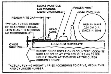
Although the heads are widely separated during disk pack insertion, they move very close to the disk surface during operation, floating on a cushion of air about one thousandth of a millimeter above the surface. The diagram below from the manual illustrates the danger of particles on the disk's surface. Any contamination can cause the head to crash into the disk surface, gouging out the oxide layer and destroying the disk and the head.
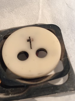
The magnified photo below shows the read/write head. The two air bleed holes ensure that the head is flying at the correct height above the disk surface. The long part of the cross contains the read/write coil, while the short part of the cross contains the erase coils (which erase a band between tracks).
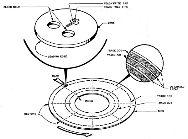
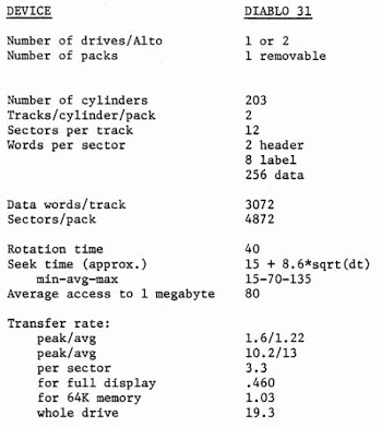
The following diagram shows how data is stored on the disk in 203 tracks (actually 203 cylinders, since there are tracks on the top and bottom surfaces). The drive moves the tiny read/write heads to the desired track. Each track is divided into 12 sectors, with 256 words of data in each sector.
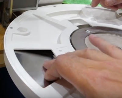
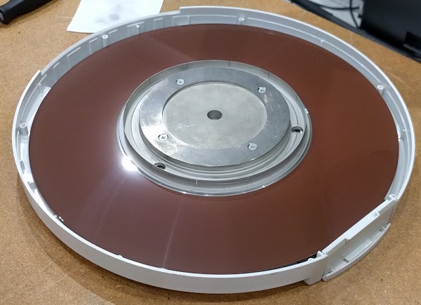
In the photo below, we have removed the top of the disk pack revealing the hard disk inside. Note the vertical metal ring along the inside of the disk; it has twelve narrow slots that physically indicate the twelve sectors of the disk. A double slot is the index mark, indicating the first sector. To make sure the disk surface was clean, we wiped the disk surfaces clean with isopropyl alcohol. This seemed a bit crazy to me, but apparently it's a normal thing to do with disks of that era.
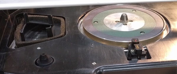
The photo below shows the motor spindle that rotates the hard disk at 1500 RPM. In front of the spindle, you can see the sensor that detects the slots that indicate sectors. To the left is the air duct that provides filtered airflow into the disk pack. (The air intake on the bottom of the disk pack was shown in an earlier photo.) Around the edge of the air duct is foam to provide a seal between the duct and the disk cartridge, ensuring airflow through the cartridge.
After 40 years, the foam had deteriorated into mush and needed to be replaced. The foam no longer provided an airtight seal. Even worse, particles could break off the foam. If a piece of foam got blown onto the disk surface, it would probably trigger a catastrophic disk crash. To replace the foam, we used weatherstripping, which isn't standard but seemed to get the job done.
As well as replacing the foam, we vacuumed any dust out of the drive and carefully cleaned the heads and other drive components.
How the Diablo drive works
The drive itself has fairly limited logic, with most of the functionality inside the Alto. The drive can seek to a particular track, indicate the current sector, and read or write a stream of raw bits. Since there's no buffering in the disk drive, the Alto must supply every bit at the precise time based on the disk's rotation. In the Alto, microcode performs many interfacing tasks that are usually done in hardware. Instead of using DMA, the Alto's microcode moves data words one at a time to the disk interface card in the Alto, which does the serial/parallel conversion.
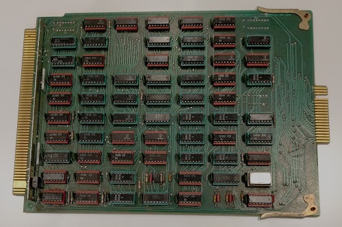
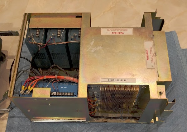
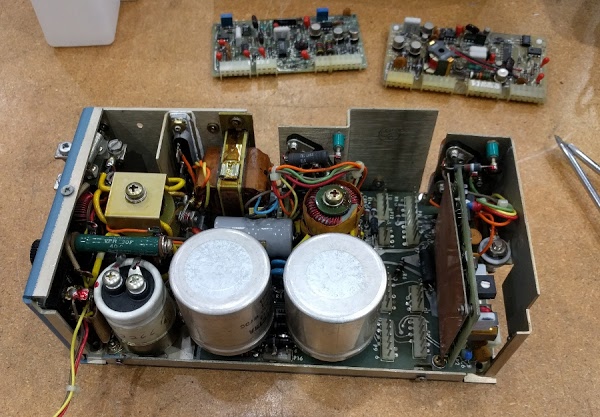
Modern disk drives use a dense disk controller integrated circuit. The Diablo drive, in contrast, implements its limited functionality with transistors and individual chips (mostly gates and flip flops), so it requires boards of components. The photo above shows the 6 main circuit boards of the Alto, plugged into the "mother board": three on the left side and three on the right side. For ease of maintenance, the electronics assembly pops up as seen above, allowing access to the boards. The leftmost board is the analog circuitry, generating the write signals for the heads and amplifying the signals read back from the disk. You can see a wire running from the board to the read/write heads. The next board detects sector and index marks and controls the motor speed. The third board has a counter to keep track of the current sector number.
The three boards on the right perform seeks, moving the disk head to the desired track. The first board computes the difference between the previous track number and the requested track number. The next board counts tracks as the head moves to determine the distance remaining. The rightmost board controls the servo that moves the head to the right track. The seek servo has a four-speed drive, so the head moves rapidly at first and slows down as it approaches the right track, more sophistication than I expected. The Diablo drive manual has detailed schematics.
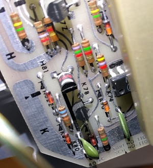
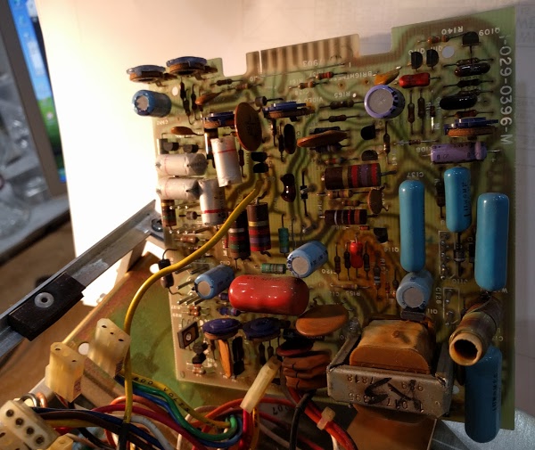
The photo below shows some of the colorful resistors and diodes on the analog read/write board, along with some transistors. Modern circuit boards would be much denser, with tightly packed surface mounted components.
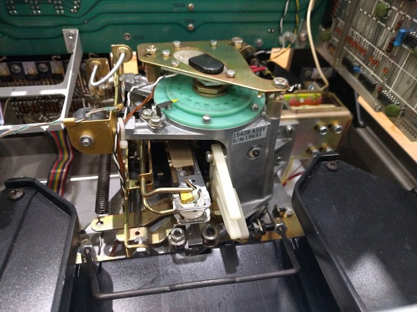
The head positioning mechanism is shown below. The turquoise circles rotate as the drive moves to a new track and the yellow pointer indicates the track number on the dial. The heads themselves are on the arm below (lower center). In front of the heads (bottom of the picture) is the metal bar that opens the disk pack when it is inserted.
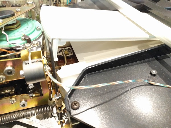
As the disk pack enters the drive, it opens up to provide access to the disk surface. The photo below shows the same mechanism as the previous photo, but from the side and with a disk inserted. You can see the exposed surface of the disk, brownish from the magnetizable iron oxide layer over the aluminum platter. As described earlier, the airflow exits the cartridge here, preventing dust from entering through this opening. The read/write head is visible above the disk's surface, with another head below the disk.
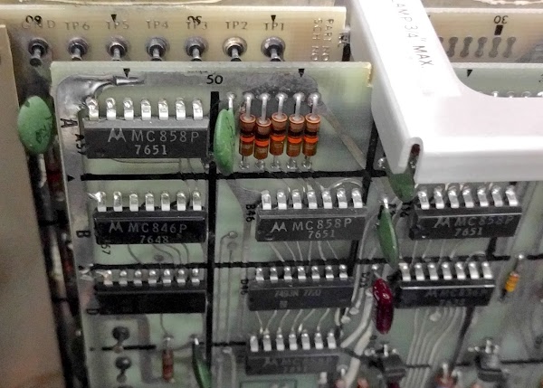
The drive largely uses primitive DTL chips—diode transistor logic, an early form of digital logic, as well as some slightly more modern TTL chips. The photo below shows some of the chips on the sector counting board. The chips labeled MC858P provide four NAND gates, so there's not much logic per chip. (7651 is the date code, indicating the chip was manufactured in week 51 of 1976.)
Conclusion
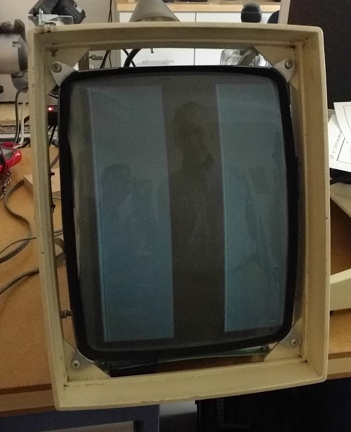
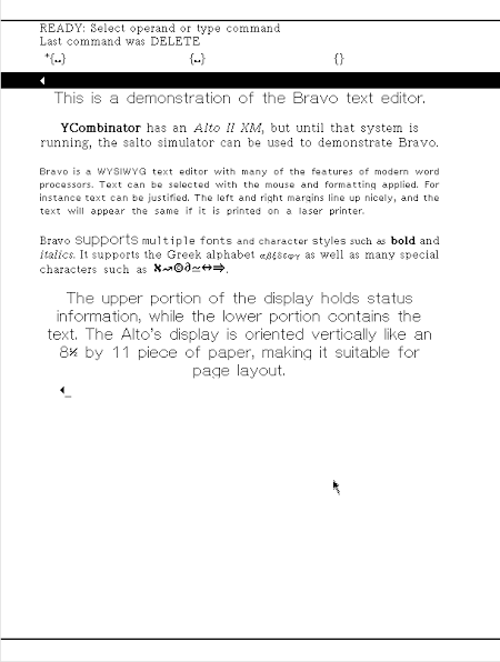
After putting the disk drive back together, we carefully powered up the system. The disk drive spun up to high speed, the heads dropped to the surface, and the disk slowed to 1500 RPM as expected. (One surprising complexity of the drive is it runs at a faster speed for a while so the airflow will blow contaminants out of the disk pack before loading the heads; it has counters and logic to implement this.) We verified that the disk surface remained undamaged, so the drive works properly, at least mechanically.This was the first time we had powered up the Alto circuitry. Happily, nothing emitted smoke. But not surprisingly, the Alto failed to boot from the disk. Unless the Alto can read boot code from the disk (or Ethernet), nothing happens, not even a prompt on the screen. The photo below shows the disk with the ready light illuminated, and the empty screen.
We have a long debugging task ahead of us, to trace through the Alto's logic circuits and find out what's going wrong. We're also building a disk emulator using a FPGA, so we will be able to run the Alto with an emulated disk, rather than depending on the Diablo drive to keep running. The restoration is likely to keep us busy for a while, so expect more updates. One item we are missing is the Alignment Cartridge (or C.E. Pack), a disk cartridge with specially-recorded tracks used to align the drive; let us know if you happen to have one lying around!
For updates on the restoration, follow kenshirriff on Twitter. Thanks to Al Kossow and Keith Hayes for assistance with restoration.
