Using arbitrary remotes with the Arduino IRremote library

My IRremote library decodes output from many infrared remotes: Sony, NEC, RC5, and RC6. However, many remotes use other protocols. While it's not too hard to add support for other protocols, I wanted to show how the library can be used with arbitrary remote controls.

This post describes a simple routine that will generate a unique code for each key on an arbitrary remote. The demo application flashes the LED the appropriate number of times when I push the 0-9 button on my remote.

How it works

The IRremote library records the duration of each (modulated) pulse sent by the remote control. Each key on the remote corresponds to a particular code value, which is converted to a particular sequence of pulses. If you know the encoding algorithm, you can determine the code value, and thus the key pressed. However, for many applications it doesn't really matter what the original code value is, as long as you can uniquely distinguish each key. Thus, if you can turn each unique sequence of pulses into a unique value, then this value will indicate the desired key.

To do this, I look at the duration of successive pulses. If the pulse is shorter than the previous, I assign 0. If the pulse is the same length, I assign 1. If the pulse is longer, I assign 2. (I compare on-durations with on-durations and off-durations with off-duations.) The result is a sequence of 0's, 1's, and 2's. I hash these values into a 32-bit hash value.

With luck, the 32-bit hash value will be unique for each key. Note that these hash values are arbitrary, and don't have any obvious connection with the underlying code value. Most encoding protocols use two different durations, so comparing shorter vs longer will work, but you can imagine a code with multiple duration values that wouldn't work here. In addition, hash collisions could occur, but are pretty unlikely with a 32-bit hash.

Code

The code can be downloaded from IRhashcode.pde. The sample application prints the "real" decoded value and the hash value. The "real" value will only work for supported protocols (Sony, RC5, RC6, NEC), but the hash value should work for almost any remote control.

The code is pretty straightforward. compare() compares the two measured durations within the 20% tolerance.

int compare(unsigned int oldval, unsigned int newval) {
  if (newval < oldval * .8) {
    return 0;
  } 
  else if (oldval < newval * .8) {
    return 2;
  } 
  else {
    return 1;
  }
}
The actual decoding is fairly simple. results->rawbuf holds the measured durations as space, mark, space, mark, ... The loop compares each duration with the next of the same type, and adds that value to the hash result.
#define FNV_PRIME_32 16777619
#define FNV_BASIS_32 2166136261
unsigned long decodeHash(decode_results *results) {
  unsigned long hash = FNV_BASIS_32;
  for (int i = 1; i+2 < results->rawlen; i++) {
    int value =  compare(results->rawbuf[i], results->rawbuf[i+2]);
    // Add value into the hash
    hash = (hash * FNV_PRIME_32) ^ value;
  }
  return hash;
}
The mystery FNV numbers come from the FNV 32-bit hash function, which combines all the values into a single 32-bit value.

The following example code prints out the "real" decoded value and the hash decoded value to the serial port. You will want to use this code to figure out what hash value is associated with each key on the remote.

void loop() {
  if (irrecv.decode(&results)) {
    Serial.print("'real' decode: ");
    Serial.print(results.value, HEX);
    Serial.print(", hash decode: ");
    Serial.println(decodeHash(&results), HEX);
    irrecv.resume(); // Resume decoding (necessary!)
  }
}
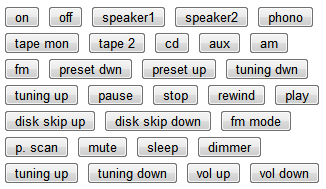
Here's a slightly more realistic example. It receives a code from a Philips remote and flashes the LED appropriately. If you press "1", it flashes once, if you press "8" it flashes 8 times, etc. The code simply uses a case statement to match against the pressed key, and blinks that many times.

You will need to modify this to work with your remote. If it doesn't recognize the code, it will print it to the serial output. Put these unrecognized values into the code to make it work with your remote.

#define LEDPIN 13
void blink() {
  digitalWrite(LEDPIN, HIGH);
  delay(200);
  digitalWrite(LEDPIN, LOW);
  delay(200);
}  

void loop() {
  if (irrecv.decode(&results)) {
    unsigned long hash = decodeHash(&results);
    switch (hash) {
    case 0x322ddc47: // 0 (10)
      blink(); // fallthrough
    case 0xdb78c103: // 9
      blink();
    case 0xab57dd3b: // 8
      blink();
    case 0x715cc13f: // 7
      blink();
    case 0xdc685a5f: // 6
      blink();
    case 0x85b33f1b: // 5
      blink();
    case 0x4ff51b3f: // 4
      blink();
    case 0x15f9ff43: // 3
      blink();
    case 0x2e81ea9b: // 2
      blink();
    case 0x260a8662: // 1
      blink();
      break;
    default:
      Serial.print("Unknown ");
      Serial.println(hash, HEX);    
    }
    irrecv.resume(); // Resume decoding (necessary!)
  }
}

Debugging

The most likely problem is a key will occasionally have different code values. This is likely due to random errors in measuring the pulses. The code considers any durations within +/- 20% to be equal; you can try increasing this value.

If you're using a RC5/RC6 remote, each key will alternate between two different values. In that case, you probably want to use the "real" decoded value, rather than the hashed value, since you can mask out the toggle bit.

If your remote uses a protocol with multiple duration values, you probably won't get unique values from this algorithm.

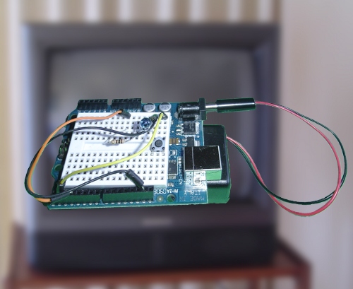
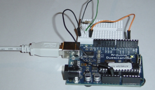
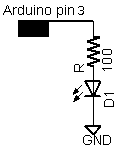
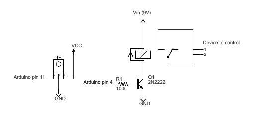
For other problems, see the IRremote page, which also has a schematic for wiring up the IR detector.

Conclusion

This IR hash algorithm extends the IRremote library to be usable with many more types of infrared remote controls. Please let me know if you use it, and I'll add a link to your project if you want.

Arc beats Python for a web-controlled stereo

I recently set up a web interface to my stereo, implementing it in both Python and Arc. I found that, much to my surprise, writing the Arc implementation was much easier than the Python implementation in this case.

In my stereo controller system, I go to a web page that has an image of the appropriate remote control, and click the button. The Javascript in the web page sends a hex code back to the server, which sends the code to an Arduino microcontroller board, which converts the code into an infrared signal. The stereo interprets this signal as a command from the remote control and performs the desired action. It sounds complicated, but it responds quickly, even if I use the browser on my cell phone. I wrote up more details on the system earlier.
Remote control on G1 phone
The web server for this project is fairly straightforward: it needs to serve some static HTML pages and images, and needs to receive POST messages and forward the data over the serial port to the Arduino. I originally wrote the code in Python:

import cgi
import serial

from BaseHTTPServer import HTTPServer
from SimpleHTTPServer import SimpleHTTPRequestHandler

class MyHandler(SimpleHTTPRequestHandler):
  def do_POST(self):
    if self.path == '/arduino':
      form = cgi.FieldStorage(fp=self.rfile, headers=self.headers,
        environ={'REQUEST_METHOD':'POST'})
      code = form['code'].value
      print 'Sent:', code
      arduino.write(code)
      self.send_response(200)
      self.send_header('Content-type', 'text/html')
      return
    return self.do_GET()

arduino = serial.Serial('/dev/ttyUSB0', 9600, timeout=2)
server = HTTPServer(('', 8080), MyHandler).serve_forever()
The Python web server is based on SimpleHTTPServer. To handle POST requests to the /arduino URL, I made a simple handler subclass that pulls the data out of the response, sends it to the serial port, and returns a blank response. The last two lines open the serial port and start up the server. The static web page serving comes "for free."

After writing this, I decided to try writing a version in Arc:

(= srvops* (table))

(= arduino-serial (outfile "/dev/ttyUSB0" 'binary))

(defopr || req "/index.html")

(defop arduino req (w/stdout (stderr)
  (let code (arg req "code")
    (write code arduino-serial)
    (prn "Sent code:" code))))

(thread (serve 8080))
Since you may not be familiar with the Arc web server, I'll give a brief explanation. The first line clears out the server's default pages (login, whoami, prompt, etc) that make sense for news.yc, but not for me. The next line opens the serial port. Next, the mysterious || redirects the home page. The next four lines are the handler for "/arduino": the "code" parameter is pulled out of the request (req). The code is written to the serial port, and printed to the log. The last line starts a serving thread on port 8080.

I'm not going to count tokens since that's a silly metric, but the Arc code is a clear winner here. The first Python disadvantage is the hideous cgi.FieldStorage call to parse the POST data; apparently this is the way to do it, but it took me considerable time to get this right. The second Python disadvantage is the necessity to set up the return code and content-type for the response. I ended up with a browser-specific bug when I didn't have this right, since some Javascript interpreters expect a particular response. Arc automatically sends a valid response. The main Arc disadvantage is there's no real serial port support; the Arc code just opens the port and hopes for the best. On the other hand, Python's serial library lets you set the baud rate, timeouts, and other parameters.

Arc and Python have a few more minor differences. Python requires imports, which Arc doesn't. Arc has the silly clearing of srvops* to avoid unwanted pages. Starting the server thread is simpler in Arc but not as flexible.

To summarize, I found the Python code difficult and error-prone to write, and the Arc code was shorter and just worked. This was a surprise to me; usually I find Python straightforward and Arc gives me pain when I have to write a bunch of code for some trivial thing it doesn't support. (For example, generating a time string in my temperature monitoring.) In this case, however, Arc came out ahead. Perhaps this is because Arc's flagship application is a web server, so it handles web serving well.

Obviously this is a fairly trivial program - the complexity is actually in the Javascript code and the C++ code on the Arduino - so I'm not claiming this as an overall victory for Arc over Python. But it's still interesting to find Arc came out ahead in this case.

TV-B-Gone for the Arduino

I've ported the TV-B-Gone code to run on the Arduino board. If you haven't seen a TV-B-Gone, it's a cute gadget that you point at a TV that's bothering you, and it turns the TV off. Internally, it's an infrared remote that broadcasts more than 100 different off codes that work on almost any TV. I figured it would be interesting to get the TV-B-Gone running on the Arduino.
TV-B-Gone running on an Arduinio

Update (November 2010)

I have a new, improved version of the software. Details and download are here.

The software

I started with the TV-B-Gone firmware, which is available under Creative Commons license. The TV-B-Gone runs on an ATtiny85 microcontroller, not the ATmega328 used by the Arduino, so some porting was required. One tricky part of the port is the IR signals are generated using the low-level hardware timer for PWM (pulse-width modulation). Since the ATtiny85 runs at 8MHz, and the Arduino runs at 16MHz, the timing code needed to be re-written, both the 10us delay loop and the timer register operations. The quick summary is I'm using Timer 2, scaling the clock by 8, using OCR2A to control the frequency and OCR2B to control the duty cycle, and have output on pin 3 (OC2B). (You are not expected to understand this. See my article on Secrets of Arduino PWM for details of how these timers work.)
#define freq_to_timerval(x) (F_CPU / 8 / x - 1)
...
    pinMode(IRLED, OUTPUT);
    TCCR2A = _BV(COM2A0) | _BV(COM2B1) | _BV(WGM21) | _BV(WGM20);
    TCCR2B = _BV(WGM22) | _BV(CS21);
...
    OCR2A = freq; 
    OCR2B = freq / 3; // 33% duty cycle
Another tricky thing is the original firmware stores the IR codes in program space, not RAM. The microcontrollers use a Harvard architecture, which means they have separate memory and data paths for code and data, unlike normal processors that use a von Neumann architecture. Because RAM storage is so small on these microcontrollers, the IR codes are stored in program space, with the result you need to use special methods to access them, rather than normal C pointers. Program memory storage is indicated with the PROGMEM macro and pulled out of memory using special functions such as pgm_read_byte. This makes the code somewhat confusing, for example:
const struct IrCode *NApowerCodes[] PROGMEM = {
  &code_na000Code,
...
}

data_ptr = (PGM_P)pgm_read_word(NApowerCodes+i);  

The original firmware stores the codes as compressed indices into tables of durations. See the TV-B-Gone design for details. Unfortunately, the Arduino's compiler didn't like the zero-length array in the IrCode structure, so I needed to rewrite the long file of codes to include another level of indirection.

Apart from these factors, porting was straightforward, and I tried to keep the original code where possible. I ripped out all the power-up and watchdog code. I replaced the low-level serial code with the Arduino's Serial library. Finally, I packaged it up into an Arduino sketch, which you can download. (Update: get the improved version here.)

The hardware

The hardware is straightfoward. I use pin 13 for the status LED; some Arduinos conveniently have an LED already wired up. Pin 3 is the PWM output to the IR LED through a 100 ohm resistor. If you want more range, add a driver transistor and use multiple IR LEDs. Pin 0 (update: pin 5) selects North American or European codes; leave it unconnected for North America and ground it for European. Pin 1 (update: 2) is connected via a pushbutton to ground to trigger the code transmission. (Update: pins have changed in the new version.)

To use the Arduino TV-B-Gone, point the IR LED at your TV, push the button, and your TV should turn off when the circuit hits the right code, which could take up to a minute. The visible LED should flash for each code that is transmitted. If the circuit doesn't work, use a cellphone camera to verify that the IR LED is transmitting. Don't expect more than a few feet range unless you use a transistor to increase the power. The code will print debugging output to the serial port if you set DEBUG in main.h.

Summary

Is the Arduino TV-B-Gone practical? If you want a TV-B-Gone that you can carry around to amaze your friends, the kit or product is much more compact, has high-powered IR outputs for longer range, and is nicely packaged. However, the Arduino platform is convenient for experimenting, and many people already have it, so I expect people will find it interesting.

You might wonder why I'm not using my Arduino Infrared Library for this project. Actually, I plan to at some point, but I wanted to get the straightforward port working first. In addition, my library will need some extensions to support all the codes that the TV-B-Gone supports.

I hope you enjoy the Arduino TV-B-Gone, and remember to use it for good, not evil!

Controlling your stereo over the web with the Arduino infrared library

Here's how you can control your stereo over the web. Not only that, but any other electronics with a IR remote control can now be controlled through your browser. You can even use your smart phone's browser to control your stereo from across the room or around the world.
Remote control on G1 phone
This project has several pieces: a simple Python web server running on your computer, an Arduino with my infrared library, and an IR LED or other emitter. The Python web server provides a web page with a graphical remote control. Clicking on the web page sends a code to the web server, which sends it over the serial port to the Arduino, which sends it to the IR LED, which controls your device.

The web server

I used a rather trivial Python web server (based on SimpleHTTPServer) that performs two tasks. First, it provides the static HTML pages and images. Second, it receives the POST requests and sends them to the Arduino using the pyserial library.

The following code excerpt shows the handler that processes POSTs to /arduino by extracting the code value out of the POST data and sending it to the Arduino over the serial line. The Python server automatically provides static pages out of the current directory by default; this is how the HTML files and images are served. The code assumes the serial port is /dev/ttyUSB0, which is typically the case on Linux.

class MyHandler(SimpleHTTPRequestHandler):
  def do_POST(self):
    if self.path == '/arduino':
      form = cgi.FieldStorage(fp=self.rfile, headers=self.headers,
        environ={'REQUEST_METHOD':'POST'})
      code = form['code'].value
      arduino.write(code)
      self.send_response(200)
      self.send_header('Content-type', 'text/html')
      return
    return self.do_GET()

arduino = serial.Serial('/dev/ttyUSB0', 9600, timeout=2)
server = HTTPServer(('', 8080), MyHandler).serve_forever()
The server can be accessed locally at http://localhost:8080. You may need to mess around with your firewall and router to access it externally; this is left as an exercise for the reader. I found that using my cell phone's browser via Wi-Fi worked surprisingly well, and over the cellular network there was just a slight lag (maybe 1/3 second).

The Arduino code

The code on the Arduino is pretty simple. It reads a command from the serial port and makes the appropriate IR library call. Commands consist of a character indicating the type of code, followed by 8 hex characters. For instance, "S0000004d1" sends the code 4d1 using Sony protocol; this is "play" on my Sony CD player. "N010e03fc" sends 010e03fc using NEC protocol; this turns my Harman Kardon stereo on. The full code is here, but some highlights:
void processSerialCode() {
  if (Serial.available() < 9) return;
  char type = Serial.read();
  unsigned long code = 0;
  // Read 8 hex characters into code (omitted)
  if (type == 'N') {
    irsend.sendNEC(code, 32);
  } 
  else if (type == 'S') {
    // Send Sony code 3 times
    irsend.sendSony(code, 12);
    delay(50);
    irsend.sendSony(code, 12);
    delay(50);
    irsend.sendSony(code, 12);
  }
  // More code for RC5 and RC6
}
In more detail, the Arduino waits for 9 characters to be available on the serial port. It then parses the hex value and calls the appropriate IR library send routine. The Arduino code does some special-case stuff for the different code types. Sony codes are transmitted three times as the protocol requires. The RC5 and RC6 protocol uses a toggle bit that is flipped on each transmission. (Disclaimer: I don't have RC5/RC6 devices, so this code is untested.) If your device uses a different protocol that the library doesn't support, you're out of luck unless you add the protocol to the library. That's probably not too hard; a couple people have already implemented new protocols.
Arduino controlling stereo via IR

The web page

Most of the smarts of the system are in the web page. In my setup, I have a HK-3370 stereo, and a Sony CDP-CE335 CD player. I took a picture of the remote for each and used an HTML image map to make each button clickable. Clicking on a button uses Ajax to POST the appropriate IR code to the server.

I use Ajax to send the code to the server to avoid reloading the web page on every click. The Javascript code is verbose but straightforward. The first part of the code creates the XML request object; unfortunately different browsers use different objects. The next part of the code creates and sends the POST request. The actual data sent to the server is, for instance, "code=N12345678" to send 0x12345678 using NEC protocol.

function button(value) {
  if (window.XMLHttpRequest) {
   request = new XMLHttpRequest();
  } else if (window.ActiveXObject) {
    try {
      request = new ActiveXObject("Msxml2.XMLHTTP");
    } catch (e) {
      try {
        request = new ActiveXObject("Microsoft.XMLHTTP");
      } catch (e) {}
    }
  }
  request.open('POST', '/arduino', true);
  request.setRequestHeader('Content-type', 'application/x-www-form-urlencoded');
  request.setRequestHeader('Content-length', value.length);
  request.setRequestHeader('Connection', 'close');
  request.send('code=' + value);
}
The clickable buttons are defined in the HTML through an image and an image map. Generating the image and the image map is the hard part of the whole project:
<img src="hk3370.png" width="268" height="800" border="0" usemap="#map" />
<map name="map">
<area shape="rect" coords="60,97,85,111" href="#" alt="on" onClick="button('N010e03fc')" />
<area shape="rect" coords="104,98,129,109" href="#" alt="off" onClick="button('N010ef906')" />
...
Each line in the map defines a region of the image as a button with a particular code. When clicked, this region will call the button function with the appropriate code, causing the code to be sent to the web server, the Arduino, and finally to the stereo. The alt text isn't actually used, but I recommend it to keep track of what button is associated with each line. The href causes the cursor to change when you go over the region, but isn't necessary.
Image of remote control in Internet Explorer

In this approach, the Arduino code and web server code are very simple, as they don't need to know the functions of the codes. A different way to implement this system would be to put the table of codes ("SONY_CD_ON" = 4d1, etc.) either in the web server code or the Arduino code.

To generate the web pages, I took a picture of the remote with my camera and cleaned up the picture with GIMP. I used the GIMP image map plugin to create the image map. I outlined each button, then filled in the URL with the appropriate IR code, and filled in the alt text with the name of the button. Finally, I copied the map file into the HTML file and edited it to use the Javascript function.

The easiest way to obtain the IR codes is to use the IRrecvDump example sketch included in my IR library. Simply press the button on your remote, see what code was sent, and put that code into the image map. Alternatively, you may be able to find codes in the LIRC database.

Once you get going, it's actually fairly quick to generate the image map. Select a button in the editor, click the physical button on the remote, copy the displayed value into the editor, and move on to the next button. As long as you don't get obsessive and start tweaking the regions to line up perfectly, it's pretty quick.

If you don't want to mess around with the image map, take a look at simple.html. This file shows how to use standard HTML buttons. Not as cool as the image, but much easier:

<input type="button" value="on" onClick="button('N010e03fc')" >
<input type="button" value="off" onClick="button('N010ef906')" >
...
Simple button arrangement

The hardware

The Arduino does the work of converting the hex code into an IR signal. The IR library uses digital PWM pin 3 as output, which must be connected to your IR emitter. I use a 100 ohm resistor to limit current. Wiring it up is trivial.
Schematic of IR connection to Arduino

I used a Tivo IR blaster that I had lying around, but a plain IR LED will work too. The following picture shows an IR blaster attached to my sterero. Note that the blaster needs to be positioned about the stereo's IR receiver; it may be easier to see the receiver with a flashlight.
IR blaster attached to stereo

Putting it all together

To summarize the steps:
  • Download the files and unpack them.
  • Get the infrared library and install it.
  • Aim the IR source at the device(s) to control, and connect it to the Arduino. (You may want to use a visible LED for testing.)
  • Connect the Arduino to the computer's USB port.
  • Compile and install IRwebremote.pde using the Arduino IDE.
  • Create HTML files for your remote controls. (This is the hard step.)
  • Run the Python server: python server.py
  • Go to http://localhost:8080 and control the devices.
This project has multiple pieces and requires customization, so it's not a plug-and-play project. I only recommend trying this if you know what you're doing. Good luck!

Lorem Ipsue: when internationalization goes bad

I recently saw a Master cable lock for sale with the interesting text "Lore Ipsum!" and "Lorem Ipsue!" underneath the word "Pull". If you've done any graphic design or web mockups, you're probably familiar with the Lorem ipsum text that's traditionally used as a placeholder. This Latin-based text is used, for instance, when you want to show the style and layout of a website, but don't want people to get distracted by the words.
Lock with text 'Lore ipsum' and 'Lorem ipsue'
Apparently when they designed the lock packaging, they put in placeholders but forgot to replace them with the French and Spanish translations ("Tirez!" and "¡Tira!"). I find "Lorem Ipsue!" in place of "Lorem Ipsum" interesting; maybe it is supposed to be a more Spanish-sounding placeholder, but I would have been more impressed by ¡Lorem Ipsum!

The moral is: make sure you check your internationalization; just because it looks foreign doesn't mean it's right.

Notes on dual-booting Windows 7 and Linux

Dual-booting Windows 7 and Linux is mostly straightforward, but I ran into a few problems. The following notes describe my setup, mostly for my own benefit.

If you're looking for a comprehensive dual-boot tutorial, try apc or Loko.

My setup

I'm running Windows 7 and Fedora 11 Linux on a Gateway SX2800.

Partitioning

I use the Gnome Partition Editior (GParted). Windows 7 conveniently includes a partition software under Disk Management, but inconveniently it can't shrink a volume by a large amount.

My partitioning setup is a bit crazy. Because I bought my computer before Windows 7 was released, I used Windows 7 beta until I got the official upgrade DVD. One unpleasant surprise is you have to reinstall to get from the beta to Windows 7 Home Premium; you can't just upgrade. I had an empty E: partition, so I installed the offical release there, transferred my files with Windows Easy Transfer, and then spent an evening reinstalling all my software. I store most of my data on a FAT32 partition D:to avoid messing around with NTFS on Fedora.

You'll probably want something simpler than what I have, but my partition table is:

$fdisk /dev/sda
...
   Device Boot      Start         End      Blocks   Id  System
/dev/sda1               1        1698    13631488   27  Unknown
/dev/sda2   *        1699       14445   102390277+   7  HPFS/NTFS
/dev/sda3           14446       27193   102398310    7  HPFS/NTFS
/dev/sda4           27194       77825   406701540    5  Extended
/dev/sda5           27194       28289     8803588+  82  Linux swap / Solaris
/dev/sda6           28290       70176   336457296    b  W95 FAT32
/dev/sda7           70177       77825    61440561   83  Linux
sda1 is a mysterious Gateway recovery partition, sda2 is C:, sda3 is E:, sda6 is D: for most of my data, and sda7 is the Linux partition.

/etc/fstab

/dev/sda7               /                       ext3    defaults        1 1
tmpfs                   /dev/shm                tmpfs   defaults        0 0
devpts                  /dev/pts                devpts  gid=5,mode=620  0 0
sysfs                   /sys                    sysfs   defaults        0 0
proc                    /proc                   proc    defaults        0 0
/dev/sda5  swap                    swap    defaults        0 0
/dev/sda6  /d   vfat auto,rw,user,sync,exec,dev,suid,uid=500,gid=500,umask=000 0 2

My GRUB config

default=1
timeout=5
splashimage=(hd0,2)/boot/grub/splash.xpm.gz
hiddenmenu
title Fedora (2.6.30.9-96.fc11.i586)
 root (hd0,6)
 kernel /boot/vmlinuz-2.6.30.9-96.fc11.i586 ro root=/dev/sda7 rhgb quiet
 initrd /boot/initrd-2.6.30.9-96.fc11.i586.img
title Windows 7
 rootnoverify (hd0,1)
 chainloader +1
Note the off-by-one: (hd0,6) boots off sda7. For Windows, you need to specify the partition with the Windows boot loader; if I try to boot E: directly with (hd0,2), I get BOOTMGR IS MISSING.

Editing the GRUB config from Linux rescue boot

Invariably I end up unable to boot Linux from my disk. To fix this, I boot from my Linux CD and then fix the GRUB config. The following assumes sda7 is the Linux partition:
mount /mnt /dev/sda7
cd /mnt/boot/grub
vi menu.lst
grub-install --root-directory=/mnt /dev/sda

Editing the Windows boot loader configuration

If you have multiple versions of Windows, you'll need to configure the Windows boot loader through bcdedit: details.

Other random errors

My Fedora Core boot failed with an infinite loop of "init: ttyx respawning too fast, stopped". The solution was to change selinux=enforcing to selinux=permissive in /etc/selinux/config.

Conclusion

The above notes are mostly for my own benefit the next time I need to configure GRUB, but maybe they'll help someone else. Disclaimer: it's very easy to lose data or mess up your system so it won't boot. Back everything up and make sure you have Linux and Windows rescue disks. Don't blame me if things go wrong.

IR Bubbles: Controlling a relay with an Arduino and an IR remote

An Arduino can be used to turn devices on and off via an infrared remote. As an entirely impractical example of how to use my Arduino infrared remote library to turn things on and off, I have set up my Arduino to turn a bubble maker on and off under remote control. The same techniques can be used to control an LED or anything else via IR remote.

Arduino blowing bubbles

The circuit is straightforward. An IR sensor is connected to the Arduino to detect the infrared signal. On the output side, I used a standard relay circuit. To control the bubble maker, I wired the relay in place of the power switch. A 5 volt source wasn't enough to close the relay I had handy, but 9 volts was. For this reason, I powered the Arduino off a 9V battery and connected the relay to Vin so the relay would get the full 9 volts. (A 9 volt AC adapter also works.)

Arduino IR relay schematic

The code

The following code controls the relay. Any detected IR code will toggle the output on or off. Press a button once on the remote and the output will turn on. Press a button again and the output will turn off. (You will, of course, need to download my Arduino infrared remote library to use this code.)
#include <IRremote.h>

int RECV_PIN = 11;
int OUTPUT_PIN = 4;

IRrecv irrecv(RECV_PIN);
decode_results results;

void setup()
{
  pinMode(OUTPUT_PIN, OUTPUT);
  pinMode(13, OUTPUT);
  irrecv.enableIRIn(); // Start the receiver
}

int on = 0;
unsigned long last = millis();

void loop() {
  if (irrecv.decode(&results)) {
    // If it's been at least 1/4 second since the last
    // IR received, toggle the relay
    if (millis() - last > 250) {
      on = !on;
      digitalWrite(OUTPUT_PIN, on ? HIGH : LOW);
    }
    last = millis();      
    irrecv.resume(); // Receive the next value
  }
}
The above code only toggles the output if there is at least a 1/4 second (250 ms) gap since the last received signal. The motivation behind this is that remotes often repeat the signal as long as the button is held down, and we don't want the output to toggle continuously. One other thing to notice is the call to resume(); after a code is received, the library stops detection until resume() is called.

I should make it clear that although the above example uses a relay output, the relay is just for example. The above code will work with any arbitrary output: you can use it to control a LED or anything else that can be controlled by an Arduino output pin.

Using two buttons

Another way you might want to use an IR remote is have one button turn the output on, and another button turn it off. Here's the loop code to use a Sony DVD remote; the "play" button turns the output on, and the "stop" button turns the output off:
void loop() {
  if (irrecv.decode(&results)) {
    if (results.value == 0x4cb92) { // Sony DVD play
      digitalWrite(OUTPUT_PIN, HIGH);
    } 
    else if (results.value == 0x1cb92) { // Sony DVD stop
      digitalWrite(OUTPUT_PIN, LOW);
    }   
    irrecv.resume(); // Receive the next value
  }
}
Just remember that you have to call resume after all decodes, not just the ones you're interested in.

Getting the codes

You may wonder how I got the Sony codes. One way is to look at the appropriate LIRC config file. (At some point I'll write up a full explanation of the LIRC config files.) An easier way is to just dump out to the serial port the codes that your Arduino receives. Press the buttons on your remote, and read out the values received:
void loop() {
  if (irrecv.decode(&results)) {
    Serial.println(results.value, HEX);
    irrecv.resume(); // Receive the next value
  }
}

Using a specific button

A third way you might want to use an IR remote is to have a specific button toggle the output on and off. Here's code that uses the Tivo button on a Tivo Series 2 remote to toggle the output on and off. Again, you can get the button code from a LIRC config file, or by dumping the output to your serial port.
void loop() {
  if (irrecv.decode(&results)) {
    if (results.value == 0xa10ce00f) { // TIVO button
      // If it's been at least 1/4 second since the last
      // IR received, toggle the relay
      if (millis() - last > 250) {
        on = !on;
        digitalWrite(OUTPUT_PIN, on ? HIGH : LOW);
      }
      last = millis();
    }    
    irrecv.resume(); // Receive the next value
  }
}

The hardware setup

Arduino relay circuit

The hardware setup is pretty simple. The above photo shows the IR detector on the left, and the relay on the right. The drive transistor, resistor, and diode are behind the relay, and the blue terminal strip is in front. The black box to the right of the Arduino is a 9V battery holder. The box underneath is just to hold everything up.

You may wonder why I placed the input and output components so far apart, and why I didn't use the protoboard power and ground buses. It turns out that the motor on the bubble maker is a nasty source of RFI interference that would jam the IR detector's signal if the wires to the bubble maker came near the IR detector wiring. Capacitors didn't help, but distance did. Most likely this won't be a problem for you, but I figured I should mention it.

In conclusion, happy hacking with the infrared library. Let me know if you do anything interesting with it!