Reverse-engineering the TL431: the most common chip you've never heard of

A die photo of the interesting but little-known TL431 power supply IC provides an opportunity to explore how analog circuits are implemented in silicon. While the circuit below may look like a maze, the chip is actually relatively simple and can be reverse-engineered with a bit of examination. This article explains how transistors, resistors, and other components are implemented in silicon to form the chip below.

Thumbnail of the TL431 die.

Die photo of the TL431. Original photo by Zeptobars.

The TL431 is a "programmable precision reference"[1] and is commonly used in switching power supplies, where it provides feedback indicating if the output voltage is too high or too low. By using a special circuit called a bandgap, the TL431 provides a stable voltage reference across a wide temperature range. The block diagram of the TL431 below shows that it has a 2.5 volt reference and a comparator[1], but looking at the die shows that internally it is quite different from the block diagram.

TL431 block diagram from Fairchild datasheet

TL431 block diagram from the datasheet

The TL431 has a long history; it was introduced in 1978[2] and has been a key part of many devices since then. It helped regulate the Apple II power supply, and is now used in most ATX power supplies[3] as well as the the iPhone charger and other chargers. The MagSafe adapter and other laptop adapters use it, as well as minicomputers, LED drivers, audio power supplies, video games and televisions.[4]

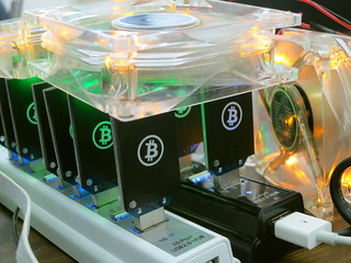
The photos below show the TL431 inside six different power supplies. The TL431 comes in many different shapes and sizes; the two most common are shown below.[5] Perhaps a reason the TL431 doesn't get much attention because it looks like a simple transistor, not an IC.

Six examples of power supplies using the TL431. Top row: cheap 5 volt power supply, cheap phone charger, Apple iPhone charger (uses TL431 and 'GB9' variant). Bottom row: MagSafe power adapter, KMS USB charger, Dell ATX power supply (with optoisolators in front)

Six examples of power supplies using the TL431. Top row: cheap 5 volt power supply, cheap phone charger, Apple iPhone charger (also 'GB9' variant in lower left). Bottom row: MagSafe power adapter, KMS USB charger, Dell ATX power supply (with optoisolators in front)

How components are implemented in the TL431's silicon

Since the TL431 is a fairly simple IC, it's possible to understand what's going on with the silicon layout by examining it closely. I'll show how the transistors, resistors, fuses, and capacitors are implemented, followed by a reverse-engineering of the full chip.

Implementing different transistor types in the IC

The chip uses NPN and PNP bijunction transistors (in contrast to chips like the 6502 that use MOSFET transistors). If you've studied electronics, you've probably seen a diagram of a NPN transistor like the one below, showing the collector (C), base (B), and emitter (E) of the transistor, The transistor is illustrated as a sandwich of P silicon in between two symmetric layers of N silicon; the N-P-N layers make a NPN transistor. It turns out that on the chip, the transistors look nothing like this. The base isn't even in the middle!

Symbol and structure of an NPN transistor.

Symbol and structure of an NPN transistor.

The photo below shows one of the transistors in the TL431 as it appears on the chip. The different pink and purple colors are regions of silicon that has been doped differently, forming N and P regions. The whitish-yellow areas are the metal layer of the chip on top of the silicon - these form the wires connecting to the collector, emitter, and base.

Underneath the photo is a cross-section drawing showing approximately how the transistor is constructed.[6] There's a lot more than just the N-P-N sandwich you see in books, but if you look carefully at the vertical cross section below the 'E', you can find the N-P-N that forms the transistor. The emitter (E) wire is connected to N+ silicon. Below that is a P layer connected to the base contact (B). And below that is a N+ layer connected (indirectly) to the collector (C).[7] The transistor is surrounded by a P+ ring that isolates it from neighboring components. Since most of the transistor in the TL431 are NPN transistors with this structure, it's straightforward to pick out the transistors and find the collector, base, and emitter, once you know what to look for.

An NPN transistor from the TL431 die, and its silicon structure.

An NPN transistor from the TL431 die, and its silicon structure.

The NPN output transistor in the TL431 is much larger than the other transistors since it needs to handle the full current load of the device. While most of the transistors are operating on microamps, this transistor supports up to 100 mA. To support this current, it is large (taking up more than 6% of the entire die), and has wide metal connections to the emitter and collector.

The layout of the output transistor is very different from the other NPN transistors. This transistor is built laterally, with the base between the emitter and collector. The metal on the left connects to the 10 emitters (bluish N silicon), each surrounded by pinkish P silicon for the base (middle wire). The collector (right) has one large contact. The emitter and base wires form nested "fingers". Notice how the metal for the collector gets wider from top to bottom to support the higher current at the bottom of the transistor. The image below shows a detail of the transistor, and the die photo shows the entire transistor.

Closeup of the high-current output transistor in the TL431 chip.

Closeup of the high-current output transistor in the TL431 chip.

The PNP transistors have an entirely different layout from the NPN transistors. They consist of a circular emitter (P), surrounded by a ring shaped base (N), which is surrounded by the collector (P). This forms a P-N-P sandwich horizontally (laterally), unlike the vertical structure of the NPN transistors.[8]

The diagram below shows one of the PNP transistors in the TL431, along with a cross-section showing the silicon structure. Note that although the metal contact for the base is on the edge of the transistor, it is electrically connected through the N and N+ regions to its active ring in between the collector and emitter.

Structure of a PNP transistor in the TL431 chip.

Structure of a PNP transistor in the TL431 chip.

How resistors are implemented in silicon

Resistors are a key component in an analog chip such as the TL431. They are implemented as a long strip of doped silicon. (In this chip, it looks like P-silicon is used for the resistors.) Different resistances are obtained by using different lengths of resistive material: the resistance is proportional to the length-to-width ratio.

The photo below shows three resistors on the die. The three long horizontal strips are the resistive silicon that forms the resistors. Yellowish-white metal conductors pass over the resistors. Note the square contacts where the metal layer is connected to the resistor. The positions of these contacts control the active length of the resistor and thus the resistance. The resistance of the resistor on the bottom is slightly larger because the contacts are slightly farther apart. The top two resistors are connected in series by the metal on the upper left.

Resistors in the TL431.

Resistors in the TL431.

Resistors in ICs have very poor tolerance - the resistance can vary 20% from chip to chip due to variations in the manufacturing process. This is obviously a problem for a precision chip like the TL431. For this reason, the TL431 is designed so the important parameter is the ratio of resistances, especially R1, R2, R3, and R4. As long as the resistances all vary in the same ratio, their exact values don't matter too much. The second way the chip reduces the effect of variation is in the chip layout. The resistors are laid out in parallel bands of the same width to reduce the effect of any asymmetry in the silicon's resistance. The resistors are also placed close together to minimize any variation in silicon properties between different parts of the chip. Finally, the next section shows how the resistances can be adjusted before the chip is packaged, to fine-tune the chip's performance.

Silicon fuses to trim the resistors

One feature of the TL431 that I didn't expect is fuses for trimming the resistances. During manufacture of the chips, these fuses can be blown to adjust the resistances to increase the accuracy of the chip. Some more expensive chips have laser-trimmed resistors, where a laser burns away part of the resistor before the chip is packaged, providing more control than a fuse.

The die photo below shows one of the fuse circuits. There is a small resistor (actually two parallel resistors) in parallel with a fuse. Normally, the fuse causes the resistor to be bypassed. During manufacture, the characteristics of the chip can be measured. If more resistance is required, two probes contact the pads and apply a high current. This will blow the fuse, adding the small resistance to the circuit. Thus, the resistance in the final circuit can be slightly adjusted to improve the chip's accuracy.

A trimming fuse in the TL431.

A trimming fuse in the TL431.

Capacitors

The TL431 contains two capacitors internally, and they are implemented in very different ways.

The first capacitor (under the TLR431A text) is a is formed from a reverse-biased diode (the reddish and purple stripes). The junction of a reverse-biased diode has capacitance, which can be used to form a capacitor (details). One limitation of this type of capacitor is the capacitance varies with voltage because the junction width changes.

A junction capacitor in the TL431 chip with interdigitated PN junctions. The die id is written in metal on top.

A junction capacitor in the TL431 chip with interdigitated PN junctions. The die id is written in metal on top.

The second capacitor is formed in an entirely different manner, and is more like a traditional capacitor with two plates. There's not much to see: it has a large metal plate with the N+ silicon underneath acting as the second plate. The shape is irregular, to fit around other parts of the circuit. This capacitor takes up about 14% of the die, illustrating that capacitors use space very inefficiently in integrated circuits. The datasheet indicates these capacitors are each 20 pF; I don't know if this is the real value or not.

A capacitor in the TL431 chip.

A capacitor in the TL431 chip.

The TL431 chip reverse-engineered

The components of the TL431, shown on the silicon die.

The TL431 die, labeled.

The diagram above indicates the components on the die of the TL431, labeled to correspond to the schematic below. From the earlier discussion, the structure of each component should be clear. The three pins of the chip are connected to the "ref", "anode", and "cathode" pads. The chip has a single layer of metal (yellowish-white) that connects the components. The schematic shows resistances in terms of an unknown scale factor R; 100 Ω is probably a reasonable value for R, but I don't know the exact value. One big surprise from looking at the die is the component values are very different from the values in previously-published schematics. These values fundamentally affect how the bandgap voltage reference work.[9]

Internal schematic of the TL431

Internal schematic of the TL431

How the chip works

Externally, the TL431's operation is straightforward. If the voltage on the ref pin input goes above 2.5 volts, the output transistor conducts, causing current flow between the cathode and anode pins. In a power supply, this increase in current flow signals the power supply control chip (indirectly), causing it to reduce the power which will bring the voltage back to the desired level. Thus, the power supply uses the TL431 to keep the output voltage stable.

I'll give a brief summary of the chip's internal operation here, and write up a detailed explanation later. The most interesting part of the chip is the temperature-compensated bandgap voltage reference.[10] The key to this is seen by looking at the die: transistor Q5 has 8 times the emitter area as Q4, so the two transistors are affected differently by temperature. The outputs of these transistors are combined by R2, R3, and R4 in the right ratio to cancel out the effects of temperature, forming a stable reference.[11][12]

The voltages from the temperature-stabilized bandgap are sent into the comparator, which has inputs Q6 and Q1; Q8 and Q9 drive the comparator. Finally, the output of the comparator goes through Q10 to drive the output transistor Q11.

Decapping the TL431 the low tech way

Getting an IC die photo usually involves dissolving the chip in dangerous acids and then photographing the die with an expensive metallurgical microscope. (Zeptobars describes their process here). I wondered what I'd end up with if I just smashed a TL431 open with Vise-Grip pliers and took a look with a cheap microscope. I broke the die in half in the process, but still got some interesting results. The picture below shows the large copper anode inside the package, which acts as a heat sink. Next to this is (most of ) the die, which is normally mounted on the copper anode where the white circle is. Note how much smaller the die is than the package.

The TL431 package, the internal anode, and most of the die.

The TL431 package, the internal anode, and most of the die.

Using a basic microscope, I obtained the photo below. While the picture doesn't have the same quality as Zeptobars', it shows the structure of the chip better than I expected. This experiment shows that you can do a basic level of chip decapping and die photography without messing around with dangerous acids. From this photo I can see that the cheap TL431s I ordered off eBay are identical to the one Zeptobars decapped. Since the Zeptobars chip didn't match published schematics, I wondered if they ended up with a strange variant chip variant, but apparently not.

Piece of the TL431 die, photographed through a microscope.

Piece of the TL431 die, photographed through a microscope.

Conclusion

Is the TL431 really the most popular IC people haven't heard of? There's no way to know for sure, but I think it's a good candidate. Nobody seems to publish data on which ICs are produced in largest quantities. Some sources say the 555 timer is the most popular chip with a billion produced every year (which seems improbably high to me). The TL431 must be high up the popularity list - you probably have a TL431 within arms-reach right now (in your phone charger, laptop power adapter, PC power supply, or monitor). The difference is that chips such as the 555 and 741 are so well-known that they are almost part of pop culture with books, T-shirts and even mugs. But unless you've worked on power supplies, chances are you've never heard of the TL431. Thus, the TL431 gets my vote for the most common IC that people are unaware of. If you have other suggestions for ICs that don't get the attention they deserve, leave a comment.

Acknowledgments

The die photos are by Zeptobars (except the photo I took). The schematic and analysis are heavily based on Cristophe Basso's work.[12] The analysis benefited from discussion with Mikhail of Zeptobars, and the Visual 6502 group, in particular B. Engl.

Notes and references

[1] Because the TL431 has an unusual function, there's no standard name for its function. Different datasheets describe it as a "adjustable shunt regulator", a "programmable precision reference", a "programmable shunt voltage reference", and a "programmable zener".

[2] I dug up some history on the origins of the TL431 from Texas Instruments' Voltage Regulator Handbook (1977). The precursor chip, the TL430, was introduced as an adjustable shunt regulator in 1976 The TL431 was created as an improvement to TL430 with better accuracy and stability and was called a precision adjustable shunt regulator. The TL431 was announced as a future product in 1977 and launched in 1978. Another future product that TI announced in 1977 was the TL432, which was going to be "Timer/Regulator/Comparator Building Blocks", containing a voltage reference, comparator, and booster transistor in one package. preliminary datasheet. But when the TL432 came out, the "building block" plan had been abandoned. The TL432 ended up being merely a TL431 with the pins in a different order, to help PC board layout. datasheet.

[3] Modern ATX power supplies (example, example) often contain three TL431s. One provides feedback for the standby power supply, another provides feedback for the main power supply, and a third is used as a linear regulator for the 3.3V output.

[4] It's interesting to look at the switching power supplies that don't use the TL431. Earlier switching power supplies typically used a Zener diode as a voltage reference. The earliest Apple II power supplies used a Zener diode as the voltage reference (Astec AA11040), but this was soon replaced by a TL431 in the Astec AA11040-B revision. The Commodore CBM-II model B used a TL430 instead of TL431, which is an unusual choice. HP-1000 minicomputers used both the TL430 (p69) and the TL431 (p73). The original IBM PC power supply used a Zener diode for reference (along with many op amps). Later PC power supplies often used the TL494 PWM controller, which contained its own voltage reference and operated on the secondary side. Other ATX power supplies used the SG6105 which included two TL431s internally.

Phone chargers usually use the TL431. Inexpensive knockoffs are an exception; they often use a Zener diode instead to save a few cents. Another exception is chargers such as the iPad charger, which use primary-side regulation and don't use any voltage feedback from the output at all. See my article on power supply history for more information.

[5] The TL431 is available in a larger variety of packages than I'd expect. Two of the photos show the TL431 in a transistor-like package with three leads (TO-92). The remaining photos show the surface-mounted SOT23-3 package. The TL431 also comes in 4-pin, 5-pin, 6-pin, or 8-pin surface-mounted packages (SOT-89, SOT23-5, SOT323-6, SO-8 or MSOP-8), as well as a larger package like a power transistor (TO-252) or an 8-pin IC package (DIP-8). (pictures).

[6] For more information on how bipolar transistors are implemented in silicon, there are many sources. Semiconductor Technology gives a good overview of NPN transistor construction. Basic Integrated Circuit Processing is a presentation that describes transistor fabrication in great detail. The Wikipedia diagram is also useful.

[7] You might have wondered why there is a distinction between the collector and emitter of a transistor, when the simple picture of a transistor is totally symmetrical. Both connect to an N layer, so why does it matter? As you can see from the die photo, the collector and emitter are very different in a real transistor. In addition to the very large size difference, the silicon doping is different. The result is a transistor will have poor gain if the collector and emitter are swapped.

[8] The PNP transistors in the TL431 have a circular structure that gives them a very different appearance from the NPN transistors. The circular structure used for PNP transistors in the TL431 is illustrated in Designing Analog Chips by Hans Camenzind, who was the designer of the 555 timer. If you want to know more about analog chips work, I strongly recommend Camenzind's book, which explains analog circuits in detail with a minimum of mathematics. Download the free PDF or get the printed version.

The structure of a PNP transistor is also explained in Principles of Semiconductor Devices. Analysis and Design of Analog Integrated Circuits provides detailed models of bipolar transistors and how they are fabricated in ICs.

[9] The transistors and resistors in the die I examined have very different values from values others have published. These values fundamentally affect the operation of the bandgap voltage reference. Specifically, previous schematics show R2 and R3 in a 1:3 ratio, and Q5 has 2 times the emitter area as Q4. Looking at the die photo, R2 and R3 are equal, and Q5 has 8 times the emitter area as Q4. These ratios result in a different ΔVbe. To compensate for this, R1 and R4 are different between previous schematics and the die photo. I will explain this in detail in a later article, but to summarize Vref = 2*Vbe + (2*R1+R2)/R4 * ΔVbe, which works out to about 2.5 volts. Note that the ratio of the resistances matters, not the values; this helps counteract the poor resistor tolerances in a chip.

In the die, Q8 is formed from two transistors in parallel. I would expect Q8 and Q9 to be identical to form a balanced comparator, so I don't understand the motivation behind this. My leading theory is this adjusts the reference voltage up slightly to hit 2.5V. B. Engl suggests this may help the device operate better at low voltage.

[10] I won't go into the details of a bandgap reference here, except to mention that it sounds like some crazy quantum device, but it's really just a couple transistors. For more information on how a bandgap reference works, see How to make a bandgap voltage reference in one easy lesson by Paul Brokaw, inventor of the Brokaw bandgap reference. A presentation on the bandgap reference is here.

[11] In a sense, the bandgap circuit in the TL431 operates "backwards" to a regular bandgap voltage reference. A normal bandgap circuit provides the necessary emitter voltages to produce the desired voltage as output. The TL431's circuit takes the reference voltage as input, and the emitter voltages are used as outputs to the comparator. In other words, contrary to the block diagram, there is not a stable voltage reference inside the TL431 that is compared to the ref input. Instead, the ref input generates two signals to the comparator that match when the input is 2.5 volts.

[12] There are many articles about the TL431, but they tend to be very technical, expecting a background in control theory, Bode plots, etc. The TL431 in Switch-Mode Power Supplies loops is a classic TL431 paper by Christophe Basso and Petr Kadanka. This explains the TL431 from the internals through loop compensation to an actual power supply. It includes a detailed schematic and description of how the TL431 operates internally. Other related articles are at powerelectronics.com. Designing with the TL431, Ray Ridley, Switching Power Magazine is a detailed explanation of how to use the TL431 for power supply feedback, and the details of loop compensation. The TL431 in the Control of Switching Power Supplies is a detailed presentation from ON Semiconductor. The TL431 datasheet includes a schematic of the chip's internals. Strangely, the resistances on this schematic are very different from what can be seen from the die.

iPad charger teardown: inside Apple's charger and a risky phony

This article is now available in Turkish iPad şarjının iç yapısı and Chinese [中文翻译版本] Apple iPad原装充电器拆解.
Apple sells their iPad charger for $19, while you can buy an iPad charger on eBay for about $3. From the outside, the chargers look the same. Is there a difference besides the price? In this article, I look inside real and counterfeit chargers and find that the genuine charger has much better construction, power quality, and most importantly safety. The counterfeit turns out to be a 5 watt charger in disguise, half the power of a genuine charger.

iPad
Counterfeit
A real Apple iPad charger (left) and a counterfeit charger (right

From the outside, the real charger (left) and counterfeit charger (right) are almost identical. If you look very closely, you can spot are a few differences in the text: The counterfeit removed "Designed by Apple in California. Assembled in China" and the manufacturer "Foxlink"[1], probably for legal reasons. (But strangely, the counterfeit still says "TM and © 2010 Apple Inc.") The counterfeit charger displays a bunch of certifications (such as UL) that it doesn't actually have. As you will see below, there is no way it could pass safety testing.

Opening up the chargers reveals big differences between them. The genuine charger on the left is crammed full of components, fitting as much as possible into the case. The counterfeit charger on the right is much simpler with fewer components and much more empty space. The Apple charger uses larger, higher-quality components (in particular the capacitors and the transformer); below you will see that these have a big effect on power quality and safety.

iPad
Counterfeit
The components inside a real iPad charger (left) and a counterfeit charger (right).

The components inside a real iPad charger (left) and a counterfeit charger (right).

One safety difference is obvious: the Apple charger has much more insulation. The upper (high-voltage) half is wrapped in yellow insulating tape. Some components are encased in shrink tubing, there are plastic insulators between some components, and some wires have extra insulation. The counterfeit charger only has minimal insulation.

The build quality of the Apple charger is much higher. In the counterfeit charger, some components are visibly crooked or askew. While this doesn't affect the circuit electrically, it indicates a lack of care in construction.

Flipping the boards over reveals that the circuitry of the genuine Apple charger is much more complex than the counterfeit. The Apple board is crammed with tiny surface-mounted components in every available spot. The counterfeit board has a lot of empty space, with just a few components. Note the reddish insulating tape in the lower center of the Apple board, another safety feature of the genuine charger.

iPad
Counterfeit
The circuit board of a real iPad charger (left) and a counterfeit charger (right).

The circuit board of a real iPad charger (left) and a counterfeit charger (right).

How the chargers work

Both the real and counterfeit chargers use similar flyback[2] switching power supply circuits. The switching power supply is the innovation that allows these chargers to be so compact, unlike the heavy "wall warts" powering older consumer electronics. The principle of a switching power supply is the power is switched on and off tens of thousands of times a second, allowing it to provide the exact amount of power required with very little power wasted as heat. In addition, the high frequencies allow the charger to use a small transformer, unlike the bulky transformers used for 60 Hz AC.

Since the counterfeit charger is much simpler, it is easier to understand how it works and I'll explain it first in reference to the picture below. The AC power enters through the white wires in the upper left. It passes through a fusible resistor, which acts as a safety fuse. Below this, the bridge rectifier contains four diodes which convert the AC into DC (at about 170 to 340 volts[3]). The input capacitor smooths out this power. The 4-pin control IC[4] monitors the charger and uses the switching transistor to turn the high-voltage DC on and off 41,000 times per second. This chopped DC is fed into the primary winding of the flyback transformer. The transformer converts this to the desired high-current 5 volts. The output diode produces DC, and the output capacitor smooths it out. Finally, the output voltage is available at the USB connector to power your iPad. A few components round out the circuit. A feedback winding on the transformer provides voltage feedback to the control IC. This winding also powers the IC; the IC power capacitor smooths out this power. Finally, the blue snubber[5] capacitor absorbs current spikes when the transistor is switched off.[6]

Counterfeit
Inside a counterfeit iPad charger

Inside a counterfeit iPad charger

The genuine iPad charger below operates on similar principles, although the circuit is more advanced. The AC input is on the lower right, and goes through a 2A fuse (in black insulation for safety). The primary has much more filtering than in the counterfeit charger with a filter coil (common mode choke), inductor, and two large electrolytic capacitors. This increases the cost, but improves the power quality. On the output side (left), the charger has two filter capacitors, including a high-quality aluminum polymer capacitor (with the magenta stripe). The Y capacitors help reduce interference.[7] The tiny NTC temperature sensor lets the charger shut down if it overheats. (I removed some of the charger's insulation to make the components visible in this photo.)

iPad
Inside a genuine iPad charger.

Inside a genuine iPad charger.

On the other side of the circuit board, things get complicated in the Apple charger. Starting with the AC input in the upper right, the charger includes additional input filters as well as spark gaps.[8] The latch release circuit[9] lets the charger reset quickly from faults. The control IC[10] provides advanced control of the charger under varying conditions. (This IC is much more complex than the control IC in the counterfeit charger.) The current sense resistor lets the IC monitor the current through the transformer and the line voltage resistors let the IC monitor the input voltage (as well as initially powering-up the IC[9]). The protection circuit uses the temperature sensor on the other side of the board to shut down if there is an over-voltage or over-temperature problem. [20]

iPad
The circuit board inside a genuine iPad charger showing the components.

The circuit board inside a genuine iPad charger showing the components.

The secondary side includes some special features for power quality. The Y-capacitor filter works with the Y capacitors to filter out noise. The output filter circuitry is more complex than in the counterfeit. Note that the real charger has a ground connection, unlike the counterfeit charger which has a plastic pin here.[11]

Both chargers use resistors to put special voltages on the USB data lines[12] to indicate the charger type, using Apple's proprietary system (details). (This is why iPads say "Charging is not supported with this accessory" with some chargers.) Through these resistors the genuine charger indicates that it is an Apple 2A charger, while the counterfeit indicates that it is an Apple 1A charger. This shows that the counterfeit is really a 5W charger packaged as a 10W charger.

When looking at these circuits up close, it's easy to forget just how small the components are. The picture below shows one of the surface-mount components (a 0-ohm resistor[13]) from the iPad charger. It is just to the left of Roosevelt's chin on the dime.

A zero-ohm resistor from the iPad charger, on top of a dime

A zero-ohm resistor

Safety, or lack thereof

Safety probably isn't something you think about when you plug in your charger, but it's important. Inside the charger is 170 volts or more with very little separating it from your iPad and you. If something goes wrong, the charger can burn up (below), injure you, or even kill you. Devices such as chargers have strict safety standards[14] - if you get a charger from a reputable manufacturer. If you buy a cheap counterfeit charger, these safety standards are ignored. You can't see the safety risks from the outside, but by taking the chargers apart, I can show you the dangers of the counterfeit.

Counterfeit iPhone
Counterfeit iPhone charger that burned up
A Counterfeit iPhone charger that burned up. Photo by Anool Mahidharia. Used with permission

Creepage and clearance

The UL regulations[14] require safe separation between the high voltage and the low voltage. This is measured by creepage - the distance between them along the circuit board, and clearance - the distance between them through air. The regulations are complex, but in general there should be at least 4mm between high-voltage circuitry and low-voltage circuitry.

iPad
The iPad charger provides safe creepage and clearance distances between the high-voltage side (bottom) and low-voltage side (top).

The iPad charger provides safe creepage and clearance distances between the primary high-voltage side (bottom) and secondary low-voltage side (top).

The image above shows how the genuine iPad charger's circuit board separates the high voltage (bottom) from the low voltage (top). The happy face on the right marks an empty region that provides a safety gap between the primary and secondary. (This is a contrast with the rest of the circuit board, which is crammed full of components.) This gap of 5.6mm provides a comfortable safety margin. The happy face on the left marks a slot in the board that separates the low voltage and high voltage. The photo below shows how an insulating fin is built into the case and through this slot to protect the USB connector. Additional reddish-brown insulating tape goes through this slot, and the whole high-voltage section is wrapped in yellow insulating tape. The result is multiple layers of protection.

iPad
The iPad charger case has a plastic fin that slides around the USB port to provide extra insulation.

The iPad charger case has a plastic fin that slides around the USB port to provide extra insulation.

The creepage distance on the counterfeit charger board below is scary - only 0.6 mm separation between low and high voltage. The sad face on the right shows where a low-voltage trace is nearly touching the high-voltage trace below. (The ruler on the right indicates millimeters.) The board isn't as bad as it could be: the happy face on the left marks a slot cut in the circuit board under the transformer to increase the creepage distance. But overall, this board is unsafe. If you use the charger in a humid bathroom and a drop of water condenses across the 0.6 mm gap, then zap!

Counterfeit
Dangerous creepage in a counterfeit iPad charger.

Dangerous creepage in a counterfeit iPad charger.

Safety in the transformer

For safety, the high-voltage and low-voltage sides of the charger must be electrically isolated.[15] But obviously the electrical power needs to get through somehow. The flyback transformer accomplishes this task by using magnetic fields to transfer the power without a dangerous direct connection. Because the transformer is a large and relatively expensive component, it is tempting to take safety and quality short cuts here. The genuine transformer (left) is considerably larger than the counterfeit (right), which is a hint of better quality and more power capacity. Disassembling the transformers shows that this is the case.

iPad
Counterfeit
The flyback transformers from an iPad charger (left) and a counterfeit charger (right). Dime and banana are for scale.

The flyback transformers from an iPad charger (left) and a counterfeit charger (right). Dime and banana are for scale.

The key safety requirement of the transformer is to separate the high-voltage windings from the low-voltage secondary winding, and the counterfeit charger fails here. The pictures below show the transformers after removing primary windings and insulating tape, revealing the secondary winding. The wires look similar at first glance, but the the genuine charger (left) has triple-insulated wire while the counterfeit (right) is uninsulated except for a thin varnish. The triple-insulated wire is an important safety feature that keeps the high voltage out even if there is a flaw in the insulating tape and in the wire's insulation. Also note the additional black and white insulation on the wires where they leave the transformer. In the counterfeit charger, the only thing separating the secondary winding from high voltage is the insulating tape. If there is a flaw in the tape or the wires shift too far, then zap!

iPad
Inside the transformer of an iPad charger, This is the triple-insulated secondary winding.
Counterfeit
The secondary winding does not have triple-insulated wiring. This is a major safety flaw in the counterfeit iPad charger.

The real charger provides much more power with much less noise

Lab measurements of the output from the chargers shows a couple problems with the counterfeit. First, the counterfeit turns out to provide at most 5.9W, not 10W. Second, the output voltage is extremely noisy and full of spikes.

The following voltage-vs-current graphs show the performance of the iPad charger (left) and counterfeit charger (right) under increasing load. The line for the real charger goes much farther to the right, showing that the real charger provides much more current. By my measurements, the real charger provides a maximum of 10.1 watts, while the counterfeit charger provides only 5.9 watts. The consequence is the real charger will charge your iPad almost twice as fast. (For details on these graphs, see my article testing a dozen chargers.) The other thing to note is the line for the Apple charger is smooth and thin, while the counterfeit charger's line is all over the place. This indicates that the power provided by the counterfeit charger is noisy and low quality.

iPad
Voltage vs current graph for iPad charger
Counterfeit
Voltage vs current graph for fake iPad charger

The next pair of graphs shows the power quality. The yellow line shows the voltage. The real charger has a stable yellow thin line, while the counterfeit charger's output has large voltage spikes. (I had to change the scale to get the output to fit on the screen, so the counterfeit charger is actually twice as bad as it appears here.) The bottom of the counterfeit charger's yellow line is wavy, due to 120 Hz ripple appearing in the output voltage.

iPad
High frequency oscilloscope trace from Apple iPad charger
Counterfeit
High frequency oscilloscope trace from counterfeit iPad charger

The orange line shows the frequency spectrum of the output: lower is better, and higher is exponentially worse. The counterfeit spectrum is much higher in general, with a large spike at the switching frequency. This shows that the counterfeit charger's power is worse across the frequency spectrum.

You might wonder if the power quality actually matters. The biggest impact it has is on touchscreen performance. The interference from bad power supplies is known to cause the touchscreen to behave erratically.[16] If your screen malfunctions when plugged into a charger, this is probably the cause.

Inside the real charger's transformer

There's more inside the transformer that you'd expect. This section does a full teardown of the transformer from the genuine charger.

iPad
A copper band surrounds the ferrite core in the flyback transformer from an iPad charger.
iPad
Removing the ferrite core and insulation reveals the double-stranded primary winding.

The first photo above shows that underneath the the first layer of yellow insulating tape, a layer of copper foil is attached to the transformer's ferrite core to ground it. Next, removing the ferrite core and more insulation reveals the double-stranded primary winding. The high-voltage input is fed into this winding.

iPad
After removing the triple-stranded bias winding and insulating tape, the secondary winding of the transformer is visible. Note the triple-insulated wires used for the secondary winding.
iPad
The next layer of insulation contains copper foil.

Underneath the primary winding and more insulating tape is the triple-stranded bias winding, which provides feedback and power to the control IC. (In the photo, this winding has been removed and is surrounding the transformer.) After removing more insulating tape, the secondary winding of the transformer is visible. As discussed in the safety section, the secondary winding has triple-insulated wires and extra insulation where the wires leave the transformer. The next layer of insulation (right) contains copper foil. This helps reduce interference.

iPad
The innermost layer of the iPad charger flyback transformer is the primary winding.

Finally, the innermost layer of the iPad charger flyback transformer is the second half of the primary winding (above). Splitting the primary winding into two layers is more expensive, but results in a better transformer due to better coupling of the magnetic fields.

In comparison, the transformer of the counterfeit charger is much lower quality. (I haven't included the pictures for reasons of space; click through to see them.) It simply has the bias winding (pic), secondary winding (pic), and primary winding (pic) , separated by insulating tape. Unlike the genuine transformer, the counterfeit saves cost by omitting the copper foil layers. The counterfeit also doesn't use the more expensive split, multi-stranded windings that the genuine charger uses. As discussed earlier, the secondary winding is plain copper wire, not triple-insulated wire, which is a significant safety flaw.

How does the iPad charger compare to the iPhone charger?

The iPad charger is considerably larger than the iPhone charger and provides twice the power. In my detailed iPhone charger teardown I looked at the internals of the iPhone charger. The iPhone charger (below) uses two circuit boards that combine to form a one inch cube, which is impressive engineering. The iPhone and iPad chargers are both flyback switching power supplies, but the feedback mechanisms are very different.[17] Overall, I like the iPhone charger more than the iPad charger from a design standpoint, mainly because of the harder engineering challenge of cramming everything into a much smaller space.

iPhone
Inside the iPhone charger: input inductor (green), Y capacitor (blue), flyback transformer (yellow), USB connector (silver). The primary circuit board is on top and the secondary board on the bottom.

Schematics

In my iPhone charger teardown, I drew up a schematic of the charger, but for the iPad chargers I didn't need to do this. The genuine iPad charger is almost identical[18] to the reference design schematic provided by iWatt. The counterfeit charger is almost identical to the schematic in the DB02A controller datasheet. You can see from the schematics that the genuine charger has a much more complex circuit than the counterfeit. (Click the thumbnails below to get to the datasheets.)

iPad
Thumbnail: Click for schematic of iPad charger based on iWatt 1691 controller.
Counterfeit
Thumbnail: Click for schematic of counterfeit iPad charger based on DB02A controller.

Is the Apple charger worth the price?

Apple's charger is expensive compared to other chargers, but is a high quality product. You should definitely stay away from the cheap counterfeit chargers, as they are low quality and dangerous. Non-Apple name brand chargers are generally good quality according to my tests, with some better than Apple. If you want to get an Apple charger without the high price, the best way I've found is to buy a used one on eBay from a US source. I've bought several for testing, and they have always been genuine.

I wrote earlier about Apple's huge profit margins on chargers. Apple has since dropped their charger prices from $29 to $19, which is more reasonable, but looking at the price of similar chargers from other manufacturers and the cost of components, I think Apple has a huge profit margin even at $19.[19]

In any case, the iPad charger is an impressive piece of engineering with a lot of interesting circuitry inside. The counterfeit charger is also impressive in its own way - it's amazing that a charger can be manufactured and sold for such a low price (if you don't care about safety and quality). Overall, you mostly get what you pay for; even if you can't tell from the outside, there are big differences inside the case.

Notes and references

[1] Foxlink (Taiwan), Foxconn (Taiwan), and Flextronics (Singapore) are all manufacturers for Apple with confusingly similar names. Foxconn is the company with controversy over employee treatment; this charger is made by Foxlink, a different company. Interestingly, the chairmen of both companies are brothers and the companies do a lot of business with each other. The companies state that they are entirely independent, though (statement, Foxlink annual report). Foxconn and Flextronics are the world's #1 and #3 largest electronics manufacturing companies according to the MMI top 50 for 2013, while Foxlink is smaller.

[2] The chargers uses a flyback design, where the transformer operates "backwards" from how you might expect. When a voltage pulse is sent into the transformer, the output diode blocks the output so there is no output - instead a magnetic field builds up in the transformer. The transformer core has a tiny air gap to help store this field. When the voltage input stops, the magnetic field collapses, transferring power to the output winding. Flyback power supplies are very common for low-wattage power supplies.

[3] You might wonder why the DC voltage inside the power supply is so much higher than the line voltage. The DC voltage is approximately sqrt(2) times the AC voltage, since the diode charges the capacitor to the peak of the AC signal. Thus, the input of 100 to 240 volts AC is converted to a DC voltage of 145 to 345 volts internally. This isn't enough to be officially high voltage but I'll call it high voltage for convenience. According to standards, anything under 50 volts AC or 120 V dc is considered extra-low voltage and is considered safe under normal conditions. But I'll refer to the 5V output as low voltage for convenience.

[4] The counterfeit charger uses a DB02A controller IC. This controller only has four pins and is in a TO-94 (SIP-4) package. (According to the official JEDEC standard, TO-94 is a bolt-like package for large SCRs. It's a puzzle why some companies use TO-94 to describe 4-pin inline packages.) According to the datasheet (Chinese), the chip is for 500mA-1000mA chargers, which explains why the counterfeit charger only produces 5 watts, instead of the 10 watts an iPad charger is supposed to produce. This controller is very inexpensive, available for ¥ 0.35 (about 6 cents).

I couldn't find any US chips similar to this chip, even after a lot of searching; it appears to be a Chinese design with datasheets only in Chinese, manufactured by "Fine Made" Shenzhen Fuman Electronics. Since the chip only has four pins, I expected it to be a trivial Ringing Choke Converter (RCC) circuit with just a couple transistors inside the chip - but I cracked it open with Vise-Grips and it turns out to be a fairly complex chip. I took a picture through a microscope of the IC die, which is about 1 mm across. One interesting feature is the many white pads around the outside of the die, which are used to blow fuses to trim various resistances in the chip. I wasn't expecting to see this level of quality and sophistication. The die has the label "N7113 802" at the right; I don't know what this indicates. Three of the four wires connect in the lower left, and the fourth in the lower right.

Die photo of the DB02A SMPS controller chip.

Die photo of the DB02A SMPS controller chip used in the counterfeit charger.

[5] When a diode or transistor switches, it creates a voltage spike, which can be controlled by a special snubber or clamp circuit. For a lot of information on snubbers and clamps, see Passive Lossless Snubbers for High Frequency PWM Conversion and Switchmode Power Supply Reference Manual.

[6] In the counterfeit charger, the switching transistor is a ALJ 13003 NPN power transistor (datasheet), apparently made by Shenzhen LongJing Microelectronics Co. This transistor is a version of Motorola's MJE 13003 switchmode transistor which was introduced in 1976 (MJE indicates power device in a plastic package). The bridge rectifier is a B6M (datasheet). The output diode is a SR260 Schottky barrier rectifier.

[7] The iPad charger uses special Y-capacitors to bridge the high-voltage and low-voltage sides of the charger. This capacitor helps reduce EMI interference, and is specially designed to avoid any safety hazard. It does, however, pass a tiny amount of electricity - if you feel a tingle from your charger, these capacitors are probably the cause. For more information on X and Y capacitors, see Kemet's presentation and Designing low leakage current power supplies.

[8] The iPad has two spark gaps next to inductor L1 (the input AC common mode choke). I couldn't find a lot of information on this sort of spark gap, but one example of it is an Infineon SMPS design, where similar spark gaps are designed to discharge accumulated charge for a 3KV lightning surge test.

[9] The Apple charger includes a "latch release circuit". If there is a fault, the control IC will shut down the charger until power is removed. However, after unplugging a charger, the input capacitors may store power for many seconds. (You may have seen LEDs remain illuminated for several seconds after unplugging devices.) The latch release circuit ensures that the charger will reset properly even if you plug it back in quickly. It does this by providing a separate diode bridge for the charger's power - this circuit has a much smaller capacitor, so it will power off quickly. (See the schematic for details.) This seems like over-engineering to me, adding extra circuitry for this rare case.

In normal use, by the way, the control IC is powered by the transformer's feedback winding. But if the control IC isn't running, the transformer won't work, leading to a chicken-and-egg situation. The solution is a startup power path where the control IC gets enough power from the AC input to start up, and then switches to the transformer.

[10] The genuine charger uses a complex control chip manufactured by iWatt, the 1691. This chip monitors the input line voltage, the current through the transformer, and the voltage feedback from the transformer. It controls the switching frequency and length of time the power is switched on, with different behavior under no load, low load, and high load, as well as constant monitoring for faults. A detailed presentation on the iW1691 is here. This chip sells for about 30 cents, but I expect Apple gets a better price.

[11] The real charger has a metal ground pin that connects to the power plug, while the counterfeit has a plastic pin. This is one difference between the chargers that is visible externally if you slide the power plug off the charger. Ironically, the US plug doesn't use the ground connection, so this is one safety issue that doesn't make any difference in practice.

[12] Apple uses a proprietary technique for the charger to indicate to the device what kind of charger it is. Different types of Apple chargers use resistances to put different voltages on the USB D+ and D- pins. For details on USB charging protocols, see my earlier references.

[13] While it would be nice to find superconductors inside the charger, unfortunately the zero-ohm resistor is a bit more than 0 ohms. While this resistor may seem pointless, it allows the manufacturers to substitute a resistor later if different transistors require it.

[14] The outside of the charger has the slightly mysterious text: "For use with information technology equipment". This indicates that the charger is covered by the safety standard UL 60950-1, which specifies the various isolation distances required. For a brief overview of isolation distances, see i-Spec Circuit Separation and some of my earlier references.

[15] Only a few special components can safely bridge the gap between the high voltage side of the charger and the low voltage side. The most obvious is the transformer. Y-capacitors can also bridge the primary and secondary side because they are designed not to pass dangerous currents, and not to short out if they fail. Optoisolators use a light signal to provide feedback between the circuits in an iPhone charger, but are not used in the iPad charger.

[16] For an explanation of why the noisy output from cheap chargers messes up touchscreens, see Noise Wars: Projected Capacitance Strikes Back. The article discusses how capacitive touchscreen ICs need to sense pico-Coulombs of charge, which is very difficult when AC noise is present. The article blames touchscreen problems on aftermarket low cost chargers.

[17] The biggest difference between the iPhone charger and the iPad charger is the feedback used to regulate the voltage. The iPhone charger measures the output voltage with a TL431 chip and sends a feedback signal to the control IC via an optoisolator. The iPad charger avoids these components by using primary-side regulation. Instead of measuring the actual output voltage, the iPad control IC looks at the voltage in the feedback winding, which should approximately match the output voltage.

[18] I noticed only a few significant differences between the iPad charger and iWatt's published 1691 charger reference design. This probably means iWatt did most of the design work for Apple.

Comparing the actual charger with the reference design shows a few filtering improvements. The charger has RC snubbers the input bridge rectifier (a rare feature also in the iPhone charger). The charger has an extra diode on the secondary for filtering, as well as a (zener?) diode in the switching transistor drive circuit. The iPad charger uses two Y-capacitors instead of one, and a R/C filter attached to the Y-capacitor on the secondary side. The charger connects line ground to secondary ground through a resistor. The reference design doesn't show the USB data resistors[12].

[19] Some people think that I'm ignoring Apple's cost of designing chargers when figuring their large profit margin. First, if you spend $2 million on design and manufacture 200 million chargers, then design adds only one cent to the cost per charger. Second, iWatt's designers deserve credit for the complex control chip and the reference design, which is most of the design work.

[20] For those interested in the components, the iPad charger's primary diodes (F6w) are 1.5A 60V Schottky Barrier Diodes (datasheet). The "T3" diodes are fast switching diodes (datasheet). The switching transistor is an Infineon SPA04N60C Cool MOS® 650V power transistor (datasheet). The bridge rectifier is a bridge: MB10S CD 0.5A bridge rectifier with high surge capacity (datasheet). The component in the protection circuit that looks like a transistor is a BAV70 dual high-speed switching diode (datasheet). The output diode is a SBR10U45SP5 10A super barrier rectifier (datasheet). The Y capacitors are 220pF 250V. The input capacitors are Samxon 10µFand 4.7µF 400v electrolytics. The output capacitors are a Koshin KLH 820µF 6.3V aluminum electrolytic, and a 820 µF 6.3V X-CON ULR aluminum polymer capacitor (which is more expensive than a regular electrolytic, but filters better because of its lower ESR).

The programming error that cost Mt Gox 2609 bitcoins

In October 2011, Mt Gox lost over 2609 bitcoins by accidentally creating transactions that can never be redeemed. (At the time, 2609 bitcoins were worth about $8000, but they would be worth almost $1.5 million dollars now.) The problem was discussed on the Bitcoin forum, but I think it's worth taking a closer look at it in light of Mt Gox's recent massive bitcoin loss and bankruptcy. This problem reveals how easy it is to lose bitcoins through software errors. It also reveals that Mt Gox has made careless and expensive programming errors before.

The problem

When you send bitcoins to an address, what happens inside the Bitcoin transaction is more complicated than you would expect. The transaction contains a tiny computer program in the Bitcoin Script language, and this program is executed to determine if the bitcoins can be spent. Normally the program requires a public key and signature in order to spend the bitcoins. The program checks that the public key matches the address you sent the bitcoins to, and the signature is valid, proving the spender of the bitcoins has the private key. If everything matches, the bitcoins can be spent.

You might wonder why Bitcoin uses such a complex system to validate transactions. The idea is that by providing a programming language, Bitcoin allows many different types of transactions, such as escrow transactions or more complex contracts.

Going into a bit more detail, a typical scriptPubKey program looks like:

OP_DUP
OP_HASH160
f2e63314c350094550c703fcdcd4850ad37d8310
OP_EQUALVERIFY
OP_CHECKSIG

This program is part of a transaction that sent bitcoins to the address 1P9LHy6K2c9cwbfSfdaaoYVAprqUYtcFnB (which in hex is the f2e633... value above). In order for that address to redeem the bitcoins, they must provide the public key for the address 1P9L... and provide the signature for the spending transaction (which proves they have the private key). Walking through the execution of the program, it first duplicates the provided public key, computes the 160-bit hash of it, and verifies that it is equal to the provided public key address. Then it checks the signature for validity. If all goes well, the bitcoins can be spent. If there is a problem, the transaction is rejected.

In Mt Gox's bad transactions, they made a small but costly error. The script is:

OP_DUP
OP_HASH160
0
OP_EQUALVERIFY
OP_CHECKSIG
Note that in place of the destination address hash, this transaction has the byte 0, representing OP_0, which pushes an empty array of bytes. Since it's impossible for the 160-bit hash to match an empty array, it's impossible for this script to complete successfully, and the bitcoins can never be spent. (For more information on how these scripts work, see my article Bitcoins the hard way).

Why does Bitcoin permit broken transactions?

You might wonder why Bitcoin permits transactions that can never be spent. Unfortunately, it would be very difficult to determine if a script can be satisfied or not. Bitcoin is designed to give people a lot of flexibility with the Script language, even though it's easy to shoot yourself in the foot. In addition, a complex algorithm to reject transactions would be very dangerous - if clients and miners disagree on the validity of a transaction, a blockchain fork will result, causing chaos.

(The computer scientists are probably yelling "halting problem" at this point. However, that doesn't apply because the Bitcoin Script language doesn't have loops so it's guaranteed to halt. A non-terminating script would be a disaster since miners and clients would lock up, so the language prohibits looping.)

In addition, it's common to lose bitcoins by using an address when you don't have the private key, and there's no way software could detect that. Strangely, people often do this on purpose. Many transactions deliberately send tiny amounts of bitcoins to bad addresses to hide text and images in the blockchain. Other people have deliberately lost over a million dollars in bitcoins in a Counterparty proof-of-burn.

Gold coins from the Fishpool Hoard. Unlike lost bitcoins, lost gold coins can sometimes be recovered.

Another interesting script bug

While analyzing coinbase transactions, I came across another interesting bug that lost bitcoins. Some transactions have the meaningless and unredeemable script:
OP_IFDUP
OP_IF
OP_2SWAP
OP_VERIFY
OP_2OVER
OP_DEPTH

That script turns out to be the ASCII text script. Instead of putting the redemption script into the transaction, the P2Pool miners accidentally put in the literal word "script". The associated bitcoins are lost forever due to this error.

Conclusion

Losing bitcoins due to programming errors is very easy. Mt Gox has lost thousands of bitcoins in the past this way, as have others. I don't know what happened to Mt Gox recently (although I know it wasn't OP_PUSHDATA2 malleability), but based on history it is worth keeping programming errors in mind.

If you want some scary reading describing other major Bitcoin losses, take a look at List of Major Bitcoin Heists, Thefts, Hacks, Scams, and Losses.

Bitcoin mining the hard way: the algorithms, protocols, and bytes

This article explains Bitcoin mining in details, right down to the hex data and network traffic. If you've ever wondered what really happens in Bitcoin mining, you've come to the right place. My previous article, Bitcoins the hard way described how I manually created a Bitcoin transaction and sent it into the system. In this article, I show what happens next: how a transaction gets mined into a block.

The purpose of mining

Bitcoin mining is often thought of as the way to create new bitcoins. But that's really just a secondary purpose. The primary importance of mining is to ensure that all participants have a consistent view of the Bitcoin data. Because Bitcoin is a distributed peer-to-peer system, there is no central database that keeps track of who owns bitcoins. Instead, the log of all transactions is distributed across the network.

The main problem with a distributed transaction log is how to avoid inconsistencies that could allow someone to spend the same bitcoins twice. The solution in Bitcoin is to mine the outstanding transactions into a block of transactions approximately every 10 minutes, which makes them official. Conflicting or invalid transactions aren't allowed into a block, so the double spend problem is avoided.

Although mining transactions into blocks avoid double-spending, it raises new problems: What stops people from randomly mining blocks? How do you decide who gets to mine a block? How does the network agree on which blocks are valid? Solving those problems is the key innovation of Bitcoin: mining is made very, very difficult, a technique called proof-of-work. It takes an insanely huge amount of computational effort to mine a block, but it is easy for peers on the network to verify that a block has been successfully mined.[1]

Each mined block references the previous block, forming an unbroken chain back to the first Bitcoin block. This blockchain ensures that everyone agrees on the transaction record. It also ensures that nobody can tamper with blocks in the chain since re-mining all the following blocks would be computationally infeasible.[2] As long as nobody has more than half the computational resources, mining remains competitive and nobody can control the blockchain.

As a side-effect, mining adds new bitcoins to the system. For each block mined, miners currently get 25 new bitcoins (currently worth about $15,000), which encourages miners to do the hard work of mining blocks. With the possibility of receiving $15,000 every 10 minutes, there is a lot of money in mining.

How mining works

Mining requires a task that is very difficult to perform, but easy to verify. Bitcoin mining uses cryptography, with a hash function called double SHA-256. A hash takes a chunk of data as input and shrinks it down into a smaller hash value (in this case 256 bits). With a cryptographic hash, there's no way to get a hash value you want without trying a whole lot of inputs. But once you find an input that gives the value you want, it's easy for anyone to verify the hash. Thus, cryptographic hashing becomes a good way to implement the Bitcoin "proof-of-work".

In more detail, to mine a block, you first collect the new transactions into a block. Then you hash the block to form a 256-bit block hash value. If the hash starts with enough zeros[3], the block has been successfully mined and is sent into the Bitcoin network and the hash becomes the identifier for the block. Most of the time the hash isn't successful, so you modify the block slightly and try again, over and over billions of times. About every 10 minutes someone will successfully mine a block, and the process starts over.

The diagram below shows the structure of a specific block, and how it is hashed. The yellow part is the block header, and it is followed by the transactions that go into the block. The first transaction is the special coinbase transaction that grants the mining reward to the miner. The remaining transactions are standard Bitcoin transactions moving bitcoins around. If the hash of the header starts with enough zeros[3], the block is successfully mined. For the block below, the hash is successful: 0000000000000000e067a478024addfecdc93628978aa52d91fabd4292982a50 and the block became block #286819 in the blockchain.

Structure of a Bitcoin block

Structure of a Bitcoin block

The block header contains a handful of fields that describe the block. The first field in the block is the protocol version. It is followed by the hash of the previous block in the blockchain, which ensures all the blocks form an unbroken sequence in the blockchain. (Inconveniently, the hash is reversed in the header.) The next field is the Merkle root,[4] a special hash of all the transactions in the block. This is also a key part of Bitcoin security, since it ensures that transactions cannot be changed once they are part of a block.[5] Next is a (moderately accurate) timestamp of the block, followed by the mining difficulty value bits.[3] Finally, the nonce is an arbitrary value that is incremented on each hash attempt to provide a new hash value. The tricky part of mining is finding a nonce that works.

Untitled

ASIC Bitcoin Miner
Photo by Mirko Tobias Schaefer, (CC BY 2.0)

A short program to mine a block

I wrote a Python program that mines the above block. The program itself is pretty simple - the hardest part of the code is computing the difficulty target from bits.[3] Otherwise it's just a loop over different nonce values. Each iteration puts the data into a structure, hashes it, and tests the result.

The following table shows the hash obtained for selected nonce values. The key point is that each nonce generates a basically-random hash value. Every so often a "lucky" nonce will generate a hash starting with some zeroes. To get a lot of zeroes, you need to try an exponentially large number of nonces. For this block, the "winning" nonce is 856192328.

noncehash
05c56c2883435b38aeba0e69fb2e0e3db3b22448d3e17b903d774dd5650796f76
128902a23a194dee94141d1b70102accd85fc2c1ead0901ba0e41ade90d38a08e
2729577af82250aaf9e44f70a72814cf56c16d430a878bf52fdaceeb7b4bd37f4
38491452381016cf80562ff489e492e00331de3553178c73c5169574000f1ed1c
3903fd5ff1048668cd3cde4f3fb5bde1ff306d26a4630f420c78df1e504e24f3c7
9900001e3a4583f4c6d81251e8d9901dbe0df74d7144300d7c03cab15eca04bd4bb
521170000642411733cd63264d3bedc046a5364ff3c77d2b37ca298ad8f1b5a9f05ba
181315200000c94a85b5c06c9b06ace1ba7c7f759e795715f399c9c1b1b7f5d387a319f
19745650000000cdccf49f13f5c3f14a2c12a56ae60e900c5e65bfe1cc24f038f0668a6c
2439898010000000ce99e2a00633ca958a16e17f30085a54f04667a5492db49bcae15d190
8561923280000000000000000e067a478024addfecdc93628978aa52d91fabd4292982a50

I should point out that I cheated by starting with a block that could be successfully mined. Most of the attempts to mine a block will fail entirely - none of the nonce values will succeed. In that case, you need to modify the block slightly and try again. The timestamp can be adjusted (which is why the timestamp in mined blocks is often wrong). New transactions can be added to the block, changing the Merkle hash. The coinbase transaction can be modified - this turns out to be very important for mining pools. Any of these changes will result in totally different hashes, so the nonce values can be tried again.

My Python program does about 42,000 hashes per second, which is a million times slower than the hardware used by real miners. My program would take about 11 million years on average to mine a block from scratch.

Mining is very hard

The difficulty of mining a block is astounding. At the current difficulty, the chance of a hash succeeding is a bit less than one in 1019. Finding a successful hash is harder than finding a particular grain of sand from all the grains of sand on Earth. To find a hash every ten minutes, the Bitcoin hash rate needs to be insanely large. Currently, the miners on the Bitcoin network are doing about 25 million gigahashes per second. That is, every second about 25,000,000,000,000,000 blocks gets hashed. I estimate (very roughly) that the total hardware used for Bitcoin mining cost tens of millions of dollars and uses as much power as the country of Cambodia.[6]

Note that finding a successful hash is an entirely arbitrary task that doesn't accomplish anything useful in itself. The only purpose of finding a small hash is to make mining difficult, which is fundamental to Bitcoin security. It seems to me that the effort put into Bitcoin mining has gone off the rails recently.

Mining is funded mostly by the 25 bitcoin reward per block, and slightly by the transaction fees (about 0.1 bitcoin per block). Since the mining reward currently works out to about $15,000 per block, that pays for a lot of hardware. Per transaction, miners are getting about $34 in mining reward and $0.10 in fees (stats).

FPGA Bitcoin mining setup with 41 Icarus

15 GH/s FPGA Bitcoin mining configuration with 41 Icarus. Photo by permission of Xiangfu Liu

Mining with a pool

Because mining is so difficult, it is typically done in mining pools, where a bunch of miners share the work and share the rewards. If you mine by yourself, you might successfully mine a block and get 25 bitcoin every few years. By mining as part of a pool, you could get a fraction of a bitcoin every day instead, which for most people is preferable.

Mining pools use an interesting technique to see how much work miners are doing. They send out a block to be mined, and get updates from a miner whenever a miner gets a partial solution. Each partial solution proves the miner is working hard on the problem and gives the miner a share in the final reward when someone succeeds in mining the block.

For instance, if Bitcoin mining requires a hash starting with 15 zeroes, the mining pool can ask for hashes starting with 10 zeroes, which is a million times easier. Depending on the power of their hardware, a miner might find such a solution every few seconds or a few times an hour. Eventually one of these solutions will start with not just 10 zeroes but 15 zeroes, successfully mining the block and winning the reward for the pool.[7] The reward is then split based on each miner's count of shares as a fraction of the total, and the pool operator takes a small percentage for overhead.[8]

Most of the time someone outside the pool will mine a block first. In that case, the pool operator sends out new data and the miners just start mining the new block. People in a pool can get edgy if a long time goes without a payout because of bad luck in mining.

Stratum: The communication between a pool and the miners

Next I'll look in detail at the communication between a miner and the mining pool. The communication between the pool and the miners is interesting. The pool must efficiently provide work to the miners and collect their results quickly. The pool must make sure miners aren't duplicating work. And the pool must make sure miners don't waste time working on a block that has already been mined.

An important issue for mining pools is how to support fast miners. The nonce field in the header is too small for fast miners since they will run through all the possible values faster than the pool can send blocks. The solution is to allow miners to update the coinbase transaction so they can put additional nonces there. This makes mining more complicated since after building the coinbase transaction the miner must recompute the Merkle hash tree and then try mining the block.

I'm going to look at the Stratum mining pool protocol that is used by many pools. (Some alternative protocols are the Getwork and Getblocktemplate protocols.) The following Python program uses the Stratum protocol to make a mining request to the GHash.IO mining pool and displays the results. (This program is a minimal demonstration; don't use this code for real mining.)

The information below is what the mining pool sends back over the network in response to the program above. Since the Stratum protocol uses JSON-RPC the results are readable ASCII rather than the binary packets used by most of Bitcoin. This provides all the data needed to start mining as part of the pool:
{"id":1,"result":[[["mining.set_difficulty","b4b6693b72a50c7116db18d6497cac52"],["mining.notify","ae6812eb4cd7735a302a8a9dd95cf71f"]],"4bc6af58",4],"error":null}

{"id":null,"params":[16],"method":"mining.set_difficulty"}

{"id":null,"params":["58af8d8c","975b9717f7d18ec1f2ad55e2559b5997b8da0e3317c803780000000100000000","01000000010000000000000000000000000000000000000000000000000000000000000000ffffffff4803636004062f503253482f04428b055308","2e522cfabe6d6da0bd01f57abe963d25879583eea5ea6f08f83e3327eba9806b14119718cbb1cf04000000000000000000000001fb673495000000001976a91480ad90d403581fa3bf46086a91b2d9d4125db6c188ac00000000",["ea9da84d55ebf07f47def6b9b35ab30fc18b6e980fc618f262724388f2e9c591","f8578e6b5900de614aabe563c9622a8f514e11d368caa78890ac2ed615a2300c","1632f2b53febb0a999784c4feb1655144793c4e662226aff64b71c6837430791","ad4328979dba3e30f11c2d94445731f461a25842523fcbfa53cd42b585e63fcd","a904a9a41d1c8f9e860ba2b07ba13187b41aa7246f341489a730c6dc6fb42701","dd7e026ac1fff0feac6bed6872b6964f5ea00bd8913a956e6b2eb7e22363dc5c","2c3b18d8edff29c013394c28888c6b50ed8733760a3d4d9082c3f1f5a43afa64"],"00000002","19015f53","53058b41",false],"method":"mining.notify"
{"id":2,"result":true,"error":null}
{"id":null,"params":[16],"method":"mining.set_difficulty"}
The first line is a response from the pool server with the subscription details. The first values are not too important. The value 4bc6af58 is the value extranonce1 that is used when building the block. Each client gets a unique value to ensure that all the mining clients generate unique blocks and don't duplicate work. The following value (4 bytes) is the length of the extranonce2_size value that the miner puts in the coinbase while mining.

The second line is a mining.set_difficulty message to our client. With a difficulty of 16, I can get a share every hour or two on my PC. In comparison, the Bitcoin mining difficulty is 3,129,573,174.52[3] - thus it's about 200 million times easier to get a share in this pool than to successfully mine a block independently. That's why people join pools.

The third line is a mining.notify notification to our client. This message defines that block for us to mine. There's a lot of data returned under "params", so I'll explain it field by field.

job_id58af8d8c
prevhash975b9717f7d18ec1f2ad55e2559b5997b8da0e3317c803780000000100000000
coinb10100000001000000000000000000000000000000000000000000000000000000
0000000000ffffffff4803636004062f503253482f04428b055308
coinb22e522cfabe6d6da0bd01f57abe963d25879583eea5ea6f08f83e3327eba9806b
14119718cbb1cf04000000000000000000000001fb673495000000001976a914
80ad90d403581fa3bf46086a91b2d9d4125db6c188ac00000000
merkle_branch["ea9da84d55ebf07f47def6b9b35ab30fc18b6e980fc618f262724388f2e9c591", ...]
version00000002
nbits19015f53
ntime53058b41
clean_jobsfalse

The job_id is used to identify this mining task if the miner reports back success.

Most of the fields are used in the block header. The prevhash is the hash of the previous block. Apparently mixing big-ending and little-endian isn't confusing enough so this hash value also has every block of 4 bytes reversed. The version is the block protocol version. The nbits indicates the difficulty[3] of the block. The timestamp ntime is not necessarily accurate.

The coinb1 and coinb2 fields allow the miner to build the coinbase transaction for the block. This transaction is formed by concatenating coinb1, the extranonce1 value obtained at the start, the extranonce2 that the miner has generated, and coinb2. The result is a transaction in Bitcoin protocol. The merkle_branch hash list lets the miner efficiently recompute the Merkle hash with the new coinbase transaction.

clean_jobs is used if the miner needs to restart the mining jobs.

After receiving this data, the miner can start generating coinbase transactions and mining blocks.

Butterfly Labs Jalapeño

Butterfly Labs Jalapeño ASIC miner, 7+ GH/s, by 0xF2, (CC BY-ND 2.0)

Creating a block for a pool

Once the miner has received the information from the pool, it is straightforward to form the coinbase transaction by joining the coinb1, extranonce1, extranonce2, and coinb2 to form a coinbase transaction. The diagram below shows how the combination of these four values forms a complete transaction, with the nonces in the middle of the coinbase script. (The block below is slightly different from the one described earlier.)

A coinbase transaction generated by the GHash.io mining pool

A coinbase transaction generated by the GHash.io mining pool

The structure of the coinbase transaction is similar to a regular transaction, but there are a few important differences. A normal transaction transfers bitcoins from inputs (usually source addresses) to outputs (usually destination addresses). A coinbase transaction is generating new bitcoins out of thin air, rather than doing a transfer, so the transaction is slightly different. The previous output hash and index are irrelevant for the coinbase transaction. the first script is the scriptSig which signs the transaction to prove ownership of the incoming bitcoins. In a coinbase transaction, this is irrelevant, so instead the field is called the coinbase and is mostly arbitrary data.[9] (Many miners hide messages in there.) The value field in the coinbase transaction is the 25 bitcoin mining reward plus any bitcoins left over from the other transactions (the left over bitcoins are treated as mining fees). Finally, both regular transactions and the coinbase transaction use the second script (scriptPubKey) to specify the recipients of the bitcoins.[10] For details on transactions, see my my previous article.

Once the coinbase transaction is created, the hash for this coinbase transaction is combined with the merkle_branch data from the pool to generate the Merkle hash[4] for the entire set of transactions. Because of the structure of the Merkle hash (explained below), this allows the hash for the entire set of transactions to be recomputed easily.

Finally, the block header is built from the new Merkle hash and the data provided by the pool, and the hash algorithm can iterate over the nonce values in the header, just like the Python program earlier. Once all the nonce values have been tried, the miner increments the extranonce2, generates a new coinbase transaction and continues.

A Bitcoin block header

A Bitcoin block header

Informing the mining pool of success

The difficulty[3] for a mining pool is set much lower than the Bitcoin mining difficulty (fewer leading zeros required), so it's much easier to get a share. When a block is hashed to the pool's difficulty, you send a simple JSON message to the mining pool to submit it:
{"method": "mining.submit", "params": ["kens.worker1", "58af8db7", "00000000", "53058d7b", "e8832204"], "id":4}
The parameters are the worker name, job id, extranonce2, time, and header nonce. This information is sufficient for the pool to build the matching coinbase transaction and header, and verify the block. If the hash meets the pool difficulty, you get a share. If the hash also meets the much, much harder Bitcoin difficulty, the block has been successfully mined. In this case the pool submits the block to the Bitcoin network and everyone with shares gets paid accordingly.

Mining for fun and profit

If you're curious about mining, it's surprisingly easy to try out mining yourself, although you'll be lucky to earn even a penny. Just create an account at a mining pool such as BTC Guild, download mining software such as cpuminer (minerd.exe), and run the software to start mining. For a pool with low difficulty, you should get shares in a few minutes; in a pool with a higher difficulty (such as GHash.IO), it may take you an hour or two to get a share, which is more frustrating.[3]

Example of Bitcoin mining

Unprofitable Bitcoin CPU mining on my PC

The screenshot above shows what mining looks like as you get shares and blocks get mined. I got lucky and it only took me a minute to successfully mine a share. A minute later someone successfully mined a block, so the pool tells everyone to start over. Another block was mined less than a minute after that - although blocks are 10 minutes apart on average, the times can vary widely. It took 12 minutes for my next share to be generated. After running for a while, I earned 0.00000043 BTC, which is a tiny fraction of a cent.

Bitcoin mining is an "arms race". Originally people could mine with the CPU on a regular PC, but that hasn't been practical for a while. Next mining was offloaded to GPUs. Now, mining is done with special-purpose ASIC hardware, which is rapidly increasing in speed. For-profit mining is very competitive, and you'll need to look elsewhere for information.

If you want to try out mining just for fun, you may prefer to mine a currency such as Dogecoin rather than Bitcoin. First, Dogecoin uses a different hash algorithm which doesn't work well with ASIC hardware, so you're not as disadvantaged compared to professional miners. Second, because dogecoins are worth much less than bitcoins, you'll end up with a much larger number of dogecoins, which seems more rewarding. For Dogecoin mining, I used the dogepool.pw pool somewhat arbitrarily. The process is almost the same as Bitcoin mining, except you use the scrypt algorithm instead of sha256d. There are many other alternative cryptocurrencies to choose from.

Notes and references

[1] Bitcoin mining seems like a NP (nondeterministic polynomial) problem since a solution can be quickly verified. However, there are a couple of issues with making this rigorous. First, since hashes are a fixed size, mining can be done in constant time (but with a very large constant of 2^256). Thus, you'd need to consider an extended mining scheme where the difficulty can go to infinity. Second, mining would need to be turned into a decision problem - e.g. instead of finding a nonce, the problem would be "Is there a successful nonce less than k". (Note that if you can solve that problem, you can rapidly find the nonce with binary search.)

With these changes, the mining problem is in NP. The next question is if it is NP-complete. That is, can an arbitrary NP-complete problem be turned into a mining problem? I believe that is currently unknown.

[2] You might wonder what happens if two miners succeed in mining a block at approximately the same time. Has the problem of conflicting transactions has just been replaced by the problem of conflicting blocks?) The rule is that only the longest chain of valid blocks is used, and the other branch is ignored. Thus, when a miner extends the chain with one of the two parallel blocks, the other block becomes an orphan block and is ignored.

Orphan blocks are fairly common, roughly one a day. For this reason, the (somewhat arbitrary) recommendation is to wait for six confirmations (about one hour) before considering a transaction solidly confirmed.

[3] I've been describing a successful hash as starting with enough zeros, but there's an official definition of difficulty. A valid block must have a hash below a target value. (Since the target starts with a bunch of zeros, so will the valid hash.)

There are two different hard-to-understand ways of representing the target. The first, bits is a mantissa/exponent representation of the target in 32 bits. The second, difficulty is the ratio between a base target and the current target. A difficulty of N is N times as difficult as this base target. The base target is 0x00000000FFFF0000000000000000000000000000000000000000000000000000, which corresponds to approximately 1 in 232 or 1 in 4.2 billion hashes succeeding.

Difficulty changes approximately every two weeks to keep the block hash rate around 1 every 10 minutes. The https://blockchain.info/stats difficulty value is 3,129,573,174.52, corresponding to a target of 00000000000000015f5300000000000000000000000000000000000000000000. Multiplying my PC's performance by the current difficulty shows it would take my PC about 35,000 years to mine a block.

The pool difficulty is important when using a mining pool. My PC can do about 12 million hashes/sec running cpuminer, so at a difficulty of 1 my PC could find a block every 6 minutes. The BTC Guild pool uses a difficulty of 2, so I get a share about every 12 minutes. GHash.IO has a minimum difficulty of 16 on the other hand, so I only get a share every hour or two on the average. (My overall earnings would be similar either way, since the shares per block scale inversely with the difficulty.)

[4] Instead of hashing all the transactions into the block directly, the transactions are first hashed together to yield a Merkle root. The Merkle root is the root of a binary Merkle tree. The idea is to start with all the transaction hashes. Pairs of hashes are hashed together to yield new hashes. The process is repeated on the new list of hashes and continues recursively until a single hash is obtained. This final root hash is the value used when computing the block. (See Wikipedia for more details.)

In the Merkle tree, each transaction is hashed. Then pairs of hashes are hashed together. Then pairs of the new hashes are hashed together, and so on, until a single hash remains. This allows the hash of a single transaction to be verified efficiently without recomputing all the hashes. One place this comes in useful is generating a new coinbase transaction for a mining pool.

The (patented) idea of a Merkle tree is if you need to modify or verify a single transaction, you don't need to recompute everything, but can just recompute the affected pairs. Personally, I think the Merkle tree is a pointless optimization for Bitcoin and for reasonable transaction numbers it would be faster to do a single large hash, rather than multiple hashes up the Merkle tree.

Here's some demonstration code to compute the Merkle root for the block I'm discussing. The 99 transaction hashes are hard-coded for convenience. The resulting Merkle root is 871714dcbae6c8193a2bb9b2a69fe1c0440399f38d94b3a0f1b447275a29978a

[5] There are a few ways that third parties can modify transactions without invalidating the signature on the transaction. This is known as transaction malleability. These modifications change the hash of the transaction. Since the hash is part of the block, a transaction has a fixed hash and cannot be modified by malleability once it has been mined into a block. (Unless the whole block is orphaned, of course.)

[6] It's hard to estimate the cost of mining because the hardware is changing so rapidly and it's unclear what is actually in use, but I'll do a rough calculation. Looking at the Bitcoin mining hardware and Mining hardware comparison pages, the HashBlaster looks like the most efficient currently available at 375 MH/s/$ and 1818 MH/s/W. The Bitcoin network is 25 billion MH/s, which works out to about $70 million hardware cost and 15 MW. (This is about the total power consumption of Cambodia.) At $0.15/kWH, that would be about $50,000/day on electricity ($300 per block or $0.70 per transaction). Since mining generates about $140,000 per day, spending $50,000 per day on electricity seems like the right ballpark. Other estimates are at Hacker News.

[7] You might wonder why a miner doesn't cheat. If they successfully mine a block, why not submit it themselves so they can claim the full mining reward, rather than splitting it? The main reason is the coinbase transaction has the pool's address, not the miner's address. If the miner submits the block bypassing the pool, the reward still goes to the pool. And if the miner changes the address, the hash is no longer valid.

[8] There are several different reward systems used by mining pools. For instance, a pool can pay out the exact amount earned from a block or an average amount. Or a pool can pay a fixed amount per share. A pool can weight shares by time to avoid miners switching between pools mid-block. These different systems can balance risk between the miners and the pool operator and adjust the variance of payments. For details, see the Bitcoin wiki here or here.

[9] I've figured out a lot of the structure of the coinbase script above. First it contains the block height (0x046063 or 286819), which is required for version 2). Next is the string '/P2SH/' which indicates the miner supports Pay To Script Hash). This is followed by a timestamp. Next is 8 bytes of the two nonces. This is followed by apparently-random data and then the text "Happy NY! Yours GHash.IO".

[10] The typical coinbase script format has changed over time. Originally, the output scripts were all pay-to-pubkey, with the script: public_key OP_CHECKSIG. This script puts the public key itself in the script. However, now about 95% of coinbase transactions use the standard pay-to-pubkey-hash script: OP_DUP OP_HASH160 addr OP_EQUALVERIFY OP_CHECKSIG. This script only includes the public key hash (the address) and requires the redeemer to provide the public key. To see the difference, compare the output scripts in this transaction and this transaction.