Showing posts sorted by date for query IR. Sort by relevance Show all posts

Decoding an air conditioner control's checksum with differential cryptanalysis

Back in 2009 I wrote an Arduino library (IRRemote) to encode and decode infrared signals for remote controls. I got an email recently from someone wanting to control an air conditioner. It turns out that air conditioner remote controls are much complicated than TV remote controls: the codes are longer and include a moderately complex checksum. My reader had collected 35 signals from his air conditioner remote control, but couldn't figure out the checksum algorithm. I decided to use differential cryptanalysis to figure out the checksum, which was overkill but an interesting exercise. In case anyone else wants to decode a similar remote control, I've written up how I found the algorithm.

My IR remote library can be used with the Arduino to send and receive signals. (This is not the air conditioner remote.)

My IR remote library can be used with the Arduino to send and receive signals. (This is not the air conditioner remote.)

The problem is to find a checksum algorithm that when given three bytes of input (left), computes the correct one byte checksum (right).

10100001 10010011 01100011 => 01110111
10100001 10010011 01100100 => 01110001
10100001 10010011 01100101 => 01110000
10100001 10010011 01100110 => 01110010
10100001 10010011 01100111 => 01110011
10100001 10010011 01101000 => 01111001
10100001 10010011 01101001 => 01111000
10100001 10010011 01101010 => 01111010
10100001 10010011 01101011 => 01111011
10100001 10010011 01101100 => 01111110
10100001 10010011 01101101 => 01111111
10100001 10010011 01101110 => 01111100
10100001 10010011 01101111 => 01111101
10100001 10010011 01110001 => 01100100
10100001 10010011 01110010 => 01100110
10100001 10010011 01110011 => 01100111
10100001 10010011 01110100 => 01100001
10100001 10010011 01110101 => 01100000
10100001 10010011 01110111 => 01100011
10100001 10010011 01110111 => 01100011
10100001 10010011 01111000 => 01101001
10100001 10010011 01101000 => 01111001
10100001 00010011 01101000 => 11111001
10100001 00010011 01101100 => 11111110
10100001 10010011 01101100 => 01111110
10100001 10010100 01111110 => 01101011
10100001 10000010 01101100 => 01100000
10100001 10000001 01101100 => 01100011
10100001 10010011 01101100 => 01111110
10100001 10010000 01101100 => 01111100
10100001 10011000 01101100 => 01110100
10100001 10001000 01101100 => 01101100
10100001 10010000 01101100 => 01111100
10100001 10011000 01101100 => 01110100
10100010 00000010 11111111 => 01111110

The idea behind differential cryptanalysis is to look at the outputs resulting from inputs that have a small difference, to see what patterns emerge (details). Finding air conditioner checksums is kind of a trivial application of differential cryptanalysis, but using differential cryptanalysis provides a framework for approaching the problem. I wrote a simple program that found input pairs that differed in one bit and displayed the difference (i.e. xor) between the corresponding checksums. The table below shows the differences.

000000000000000000000001 : 00000001
000000000000000000000010 : 00000010
000000000000000000000010 : 00000011
000000000000000000000100 : 00000100
000000000000000000000100 : 00000110
000000000000000000000100 : 00000111
000000000000000000001000 : 00001100
000000000000000000001000 : 00001110
000000000000000000001000 : 00001111
000000000000000000010000 : 00010000
000000000000100000000000 : 00001000
000000000001000000000000 : 00011000
000000001000000000000000 : 10000000

The first thing to notice is that changing one bit in the input causes a relatively small change in the output. If the checksum were something cryptographic, a single bit change would entirely change the output (so you'd see half the bits flipped on average). Thus, we know we're dealing with a simple algorithm.

The second thing to notice is the upper four bits of the checksum change simply: changing a bit in the upper four bits of an input byte changes the corresponding bit in the upper four bits of the output. This suggests that the the three bytes are simply xor'd to generate the upper four bits. In fact, my reader had already determined that the xor of the input bytes (along with 0x20) yielded the upper four bits of the checksum.

The final thing to notice is there's an unusual avalanche pattern in the lower four bits. Changing the lowest input bit changes the lowest checksum bit. Changing the second-lowest input bit changes the second-lowest checksum bit and potentially the last checksum bit. Likewise changing the fourth-lowest input bit changes the fourth-lowest checksum bit and potentially the bits to the right. And the change pattern always has 1's potentially followed by 0's, not a mixture. (1100, 1110, 1111)

What simple operation has this sort of avalanche effect? Consider adding two binary numbers. If you change a high-order bit of an input, only that bit will change in the output. If you change a low-order input bit, the low-order bit of the output will change. But maybe there will be a carry, and the next bit will change. And if there's a carry from that position, the third bit will change. Likewise, changing a bit in the middle will change that bit and potentially some of the bits to the left (due to carries). So if you change the low-order bit, the change in the output could be 0001 (no carry), or 0011, or 0111, or 1111 (all carries). This is the same pattern seen in the air conditioner checksums but backwards. This raises the possibility that the checksum is using a binary sum, but we're looking at the bits backwards.

So I made a program that reversed the bits in the input and output, and took the sum of the four bits from each byte. The output below shows the reversed input, the sum, and the 4-bit value from the correct checksum. Note that the sum and the correct value usually add up to 46 or 30 (two short of a multiple of 16). This suggested that the checksum is (-sum-2) & 0xf.

110001101100100110000101 32 14
001001101100100110000101 22 8
101001101100100110000101 30 0
011001101100100110000101 26 4
111001101100100110000101 34 12
000101101100100110000101 21 9
100101101100100110000101 29 1
010101101100100110000101 25 5
110101101100100110000101 33 13
001101101100100110000101 23 7
101101101100100110000101 31 15
011101101100100110000101 27 3
111101101100100110000101 35 11
100011101100100110000101 28 2
010011101100100110000101 24 6
110011101100100110000101 32 14
001011101100100110000101 22 8
101011101100100110000101 30 0
111011101100100110000101 34 12
111011101100100110000101 34 12
000111101100100110000101 21 9
000101101100100110000101 21 9
000101101100100010000101 21 9
001101101100100010000101 23 7
001101101100100110000101 23 7
011111100010100110000101 17 13
001101100100000110000101 15 0 *
001101101000000110000101 19 12 *
001101101100100110000101 23 7
001101100000100110000101 11 3
001101100001100110000101 12 2
001101100001000110000101 12 3 *
001101100000100110000101 11 3
001101100001100110000101 12 2
111111110100000001000101 23 7

That formula worked with three exceptions (marked with asterisks). Studying the exceptions showed that adding in byte 1 bit 3 and byte 2 bit 7 yielded the correct answer in all cases.

Conclusion

Putting this together yields the following algorithm (full code here):

inbytes = map(bitreverse, inbytes)
xorpart = (inbytes[0] ^ inbytes[1] ^ inbytes[2] ^ 0x4) & 0xf
sumpart = (inbytes[0] >> 4) + (inbytes[1] >> 4) + (inbytes[2] >> 4) +
  (inbytes[2] & 1) + ((inbytes[1] >> 3) & 1) + 1
sumpart = (-sumpart) & 0xf
result = bitreverse((sumpart << 4) | xorpart)

Is this the right formula? It gives the right checksum for all the given inputs. However, some bits never change in the input data; in particular all inputs start with "101000", so there's no way of knowing how they affect the algorithm. They could be added to the sum, for instance, replacing the constant +1. The constant 0x4 in the xor also makes me a bit suspicious. It's quite possible that the checksum formula would need to be tweaked if additional input data becomes available.

I should point out that determining the checksum formula is unnecessary for most air conditioning applications. Most users could just hard-code the checksums for the handful of commands they want to send, rather than working out the general algorithm.

Thanks to Antonio Martinez Lavin, maker of the Cuby air conditioner controller for posing this problem. If you want to use my IR library, it is on GitHub. I'm no longer actively involved with the library, so please post issues on the GitHub repository rather than on this blog post. Thanks to Rafi Kahn, who has taken over library maintenance and improvement.

Follow me on Twitter or RSS to find out about my latest blog posts.

Restoring YC's Xerox Alto day 10: New boards, running programs, mouse problems

Last week our vintage Alto was crashing; we traced the problem to an incompatibility between two of the processor boards. Today we replaced these boards and now we can run all the programs on the disk without crashes. Unfortunately our mouse still doesn't work, which limits what we can do on this GUI-based computer. We discovered that the mouse has the wrong connector; even though it plugs in fine, it doesn't make any electrical connection.

If you're just joining, the Alto was a revolutionary computer designed at Xerox PARC in 1973 to investigate personal computing. It introduced the GUI, Ethernet and laser printers to the world, among other things. Y Combinator received an Alto from computer visionary Alan Kay and I'm helping restore the system, along with Marc Verdiell, Carl Claunch Luca Severini, Ed Thelen, and Ron Crane,

Incompatibility in the Alto's circuit boards

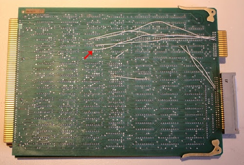
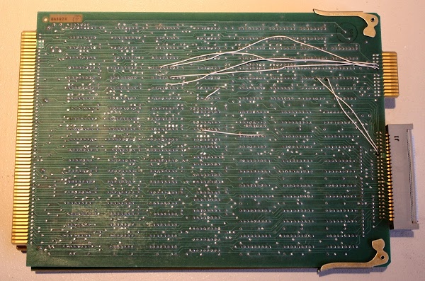
The Xerox Alto was designed before microprocessor chips, so its processor is built from three boards full of TTL chips: the ALU (Arithmetic-Logic Unit) board, the Control board, and the CRAM (Control RAM) board. The Control board and the CRAM board are the ones that we dealt with today. Last week we traced through software execution, microcode, and hardware circuitry to figure out why some programs on the Alto crashed. We discovered that the problem happened when a program attempted to execute microcode stored in the Control RAM. The microcode RAM select circuit malfunctioned due to some wiring added to the back of the Control board (the white wires in the photo below). Why had this wiring been added to the board? And why did it break things? At the end of last episode, we briefly considered ripping out this wiring, but figured we should understand what was going on first.

This is the Xerox Alto control board, one of three boards that make up the CPU. The board has been modified with several white wires.

This is the Xerox Alto control board, one of three boards that make up the CPU. The board has been modified with several white wires which trigger our crashes.

A bit of explanation will help understand what's going on. Like most computers, the Xerox Alto's instruction set is implemented in microcode. The Alto is more flexible than most computers, though, and allows user programs to actually change the instruction set by modifying the microcode, actually changing the instruction set. To achieve this, the Alto stores microcode in a combination of RAM and ROM.[1] The default microcode (used for booting and for standard programs) is stored in 1K of ROM on the Control board. Some programs use custom microcode, which allows them to modify the computer's instruction set for better performance. This microcode is stored in high-speed RAM on the Control RAM (CRAM) board. Our Alto came with a 1K CRAM board, but some programs (such as Smalltalk) required the larger 3K CRAM board.[2] (This microcode RAM is entirely different from the 512 Kbyte RAM used by Alto programs; you didn't need to fit an Alto program into 3K.)

Inconveniently, the 1K and 3K RAM boards have incompatible connections, and the Control board needs to be wired to work with one or the other. We determined that the white-wire modifications on our Control board converted it from working with a 1K RAM board to working with a 3K RAM board.[3] Unfortunately, our Alto had a 1K RAM board so the two boards were incompatible and programs that attempted to use the microcode RAM crashed, as we saw last week. It's a mystery why our Alto had two incompatible board types, but at least we knew why the modifications are there. (Since our Alto also came with the wrong disk interface card and an unbootable hard disk, we wonder what happened to the Alto since it was last used. It clearly wasn't left in a usable state.)

Fortunately Al Kossow of bitsavers came to our rescue and supplied us with some 3K Control RAM boards and the Control boards to go with them. This saved us from needing to rewire the board we had. Al also provided the strange but necessary connector (visible below on the left) that goes between the Control board and the CRAM board. We swapped these boards with our boards and everything worked without crashing! We could now run all the programs on the disk without crashes.

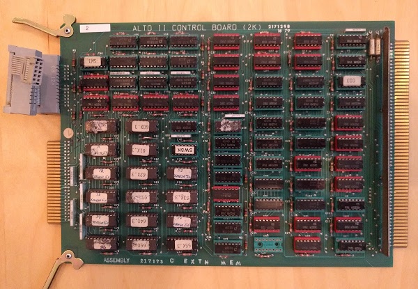
The Alto's Control board is part of the CPU. This board contains 2K words of microcode ROM, as well as control circuitry.

The Alto's Control board is part of the CPU. This board contains 2K words of microcode ROM, as well as control circuitry. Our original board had 1K of ROM (and 8 empty sockets), while this board has the full 2K of ROM. The ROM chips are in the lower left, with labels. The chip labeled SW3K (upside down) is the PROM that selects the hardware configuration. The spare PROM (labeled SW1) is in the upper left. The edge connector on the right plugs into the backplane, while the two connectors on the left are cabled to the CRAM board.

Some Alto software

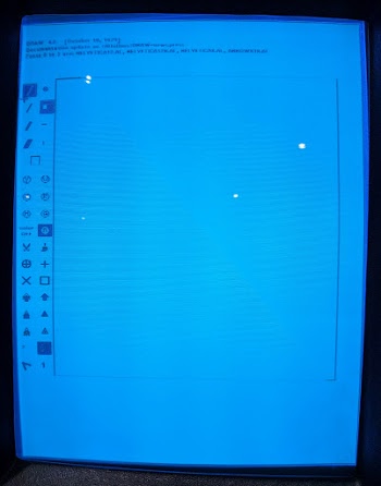
With the Alto running reliably, we could try out the various programs on the hard disk that had crashed before. Draw, the Alto's mouse-based drawing program, apparently uses microcode for optimizing performance, so last week it immediately dropped into the Swat debugger. With the compatible boards, Draw ran successfully. Unfortunately, since our mouse isn't working, we couldn't actually draw anything, but you can still see the icon-based GUI below. I've tried Draw on the Alto simulator, and despite the icons, it's not exactly intuitive to use.

'Draw' is the Alto's mouse-based drawing program. Clicking an icon on the left selects an operation.

'Draw' is the Alto's mouse-based drawing program. Clicking an icon on the left selects an operation.

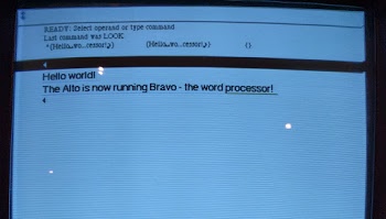
We also tried Bravo, the first WYSIWYG (What you see is what you get) text editor. Again, functionality is limited without the mouse. But I could enter text and change the font to a larger, bold font with proportional spacing. Xerox PARC also invented the laser printer and Ethernet, so one could create documents in Bravo and then print them on a networked laser printer. Charles Simonyi, one of the co-authors of Bravo, later created Microsoft Word, so there's a direct connection between the Alto's editor and Word. I've written more about how to use Bravo here.

'Bravo' is the Alto's WYSIWYG text editor. It supports multiple fonts, among other features.

'Bravo' is the Alto's WYSIWYG text editor. It supports multiple fonts, among other features.

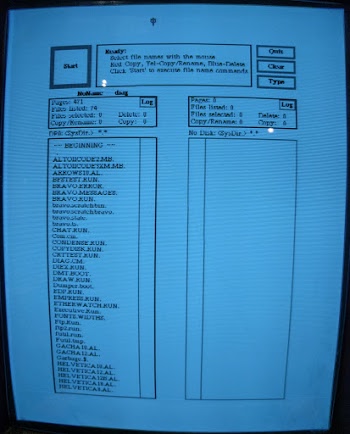
The Alto included a GUI file manager called Neptune, allowing files and directories to be manipulated with the mouse. Neptune has an invisible scroll bar to the left of the file list that appears when you mouse-over it; apparently the Alto also invented the scroll bar.

The Alto includes a graphical file system browser.

The Alto includes a graphical file system browser.

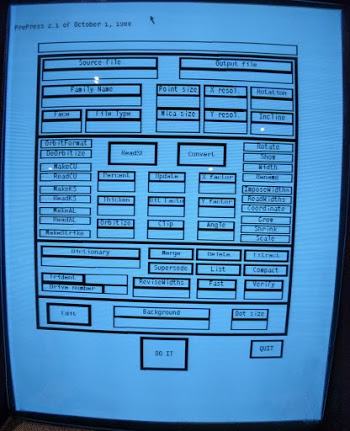
A rather complex GUI is in PrePress, a program that converted a spline-based font to a bitmapped font for display or printing. (You can think of this as a forerunner of TrueType fonts.) High-quality fonts were created for the Alto using the FRED font editor. As you would expect from a document company, these fonts included proportional spacing, ligatures such as "ffl" and "fl", and multiple styles and sizes.

'PrePress' is used to convert a spline-based font into a bitmap suitable for display or printing.

'PrePress' is used to convert a spline-based font into a bitmap suitable for display or printing.

Most importantly, we were able to run MADTEST, the Microcoded Alto Diagnostic test, which runs a suite of low-level diagnostics using microcode. This test ran successfully, increasing our confidence that there are no obscure problems in the processor.

If you want to try these Alto programs for yourself, you can use the ContrAlto simulator, built by the Living Computer Museum. This simulator has been very useful to use for learning how the software is supposed to work.

The mouse

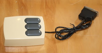
The biggest problem remaining at this point is the mouse doesn't work, so we investigated that next. Although the mouse was invented prior to the Alto, the Alto was the first computer to include the mouse as a standard input device. The Alto uses a three-button mouse that plugs into the back of the keyboard.

The three-button optical mouse.

The three-button optical mouse.

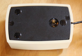
Some Altos had a mechanical mouse, while others had an optical mouse. Our Alto came with an optical mouse, but we couldn't get it to work at all. The mouse uses a special mousepad with a specific dotted pattern (which we didn't have), so at first we suspected that was the problem. However, the mouse didn't respond at all when we used a printed copy of the pattern. We also didn't see any light (visible or IR) from the three illumination LEDs on the mouse, so we suspected bigger problems than a missing mousepad.

Underside of the mouse. The sensor (right) consists of three illumination LEDs surrounding the optical sensor.

Underside of the mouse. The sensor (right) consists of three illumination LEDs surrounding the optical sensor.

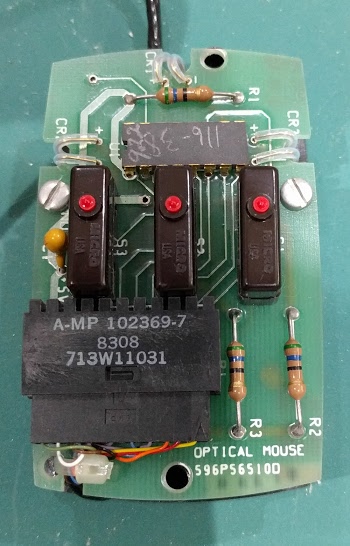
Opening up the mouse shows the simple circuitry inside, with a single chip controlling it. The chip is rather unusual since it includes a 16-pixel optical sensor, with a light guide that goes from the bottom of the chip to the bottom of the mouse. The pixel-based optical mouse was invented at Xerox PARC in 1980 (and later patented), so this mouse is somewhat more modern than the original Alto (1973). The handwritten markings on the chip suggest this may have been a prototype of some sort.

Inside the optical mouse. In the middle are the three buttons. At top is the IC that contains the optical sensor.

Inside the optical mouse. In the middle are the three buttons. At top is the IC that contains the optical sensor.

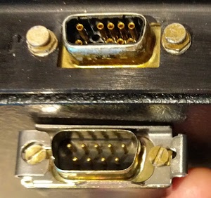
When we closely looked at how the mouse was wired up, we discovered the problem. The mouse plugs into a 19-pin socket (DE-19), while the mouse used a 9-pin plug (usually called DB-9, but technically DE-9), so the connectors are entirely incompatible. The DE-19 has three rows of pins: 6/7/6 (with the middle row empty on the Alto), and the DB-9 has two rows of pins (7/6). The bizarre thing is that the mouse plugged into the socket just fine: the connector shells are physically the same size, and the mouse plug's pins went between the Alto socket's connections. So the mouse was plugged in, but not actually connected to anything! It's surprising the connectors could go together without bending any pins. (Several people have suggested sources for a DB-19 connector. Unfortunately the DE-19 (three rows) has a totally different shape from the DB-19 (two rows).)

The Alto's mouse plugs into the 19-pin connector on the keyboard housing (above). Unfortunately our mouse has a 9-pin connector (below).

The Alto's mouse plugs into the 19-pin connector on the keyboard housing (above). Unfortunately our mouse has a 9-pin connector (below).

After some investigation, we learned that the Alto was missing the mouse when it came from Alan Kay. YCombinator picked up a replacement mouse on eBay, but it wasn't compatible with our Alto. We're still trying to figure out if the mouse is an Alto mouse with a nonstandard connector or if it is for a different machine. The Xerox Star used a 2-button mouse, so the mouse isn't from a Star. Tim Curley at Xerox PARC loaned us a compatible Alto mouse, so we'll give that one a try next episode. We're also looking into making an adapter cable, but DE-19 connectors appear to be obsolete and difficult to find.

Conclusion

Last week we discovered that the control board in our Alto was incompatible with the microcode RAM board. Al Kossow loaned us some compatible boards, and with those boards our Alto has been functioning without any crashes or malfunctions. We discovered that our mouse wasn't working because it had the wrong connector—although it plugged into the Alto, it didn't make any electrical connection. Since the mouse is necessary for many Alto programs, we hope to get the mouse working soon.

For updates on the restoration, follow me on Twitter at kenshirriff. Thanks to Al Kossow for helping us out again.

Notes and references

[1] The table below shows the three microcode configurations the Alto supported. Details are in section 8.4 of the Hardware Manual. The desired configuration is selected by inserting a particular PROM in the Control board: SW1, SW2, or SW3K. Each control board has one PROM in use and an unused PROM in the upper left corner; switching PROMs switches the configuration. The Control board has sockets for 2K of ROM; these sockets are left empty for systems with 1K of ROM.

Configuration NameROMRAM
1K1K1K
2K2K1K
3K1K3K

[2] The Alto introduced the 3K RAM board to take advantage of the new 4 kilobit RAM chips, replacing the 1 kilobit chips on the 1K board. Both boards required 32 RAM chips for the 32-bit micro-instructions, showing that back then you needed a lot of chips for not much memory. The microcode required high-speed static memory, so density was worse with microcode than with regular RAM.

[3] The 3K RAM board requires a few additional signals from the Control board, such as the task id. The 1K RAM board grounds one of the lines used for these signals, so using the 3K Control board with the 1K RAM board (as our Alto did) shorts out one of the bank select lines. This causes bank switching to fail and explains the crashes we saw last week. Schematics for the boards are available at bitsavers.

Restoring YCombinator's Xerox Alto day 5: Microcode tracing with a logic analyzer

In today's Xerox Alto restoration session we investigated why the system doesn't boot. We find a broken wire, hook up a logic analyzer, generate a cloud of smoke, and discover that memory problems are preventing the computer from booting. (In previous episodes, we fixed the power supply, got the CRT display working and cleaned up the disk drive: days 1, 2, 3. and 4.)

The Alto was a revolutionary computer, designed at Xerox PARC in 1973 to investigate personal computing. It introduced the GUI, Ethernet and laser printers to the world, among other things. Y Combinator received an Alto from computer visionary Alan Kay and I'm helping restore the system, along with Marc Verdiell, Luca Severini, Ron Crane, Carl Claunch and Ed Thelen (from the IBM 1401 restoration team).

The broken wire

The Xerox Alto is built from 13 circuit boards, crammed with TTL chips. In 1973, minicomputers such as the Alto were built from a whole bunch of simple ICs instead of a primitive microprocessor chip. (People still do this as a retro project.) The Alto's CPU is split across 3 boards: an ALU board, a control board, and a control RAM board. The control board is the focus of today's adventures.

If a circuit board has a design defect or needs changes, it can be modified by attaching new wires to create the necessary connections. The photo below shows the control board with several white modification wires. While examining the control board, we noticed one of the wires had come loose. Could the boot failures be simply due to a broken wire?

Control board from the Xerox Alto, showing a broken wire. The white wires were for a modification, but one wire came loose.

Control board from the Xerox Alto, showing a broken wire. The white wires were for a modification, but one wire came loose.

We carefully resoldered the wire and powered up the system. The disk drive slowly came up to speed and the heads lowered onto the disk surface. We pressed the reset button (under the keyboard) to boot. As before, nothing happened and the display remained blank. Fixing the wire had no effect.

After investigation, it appears the rework wires were to support the Trident/Tricon hard disk. In the photo above, note the small edge connector in the upper right, with the white wires connected. The Trident disk controller used this connector, but our (Diablo) disk controller does not. In other words, the broken wire might have caused problems with a different disk drive, but it was irrelevant to us.

Microcode on the Xerox Alto

Some background on the Xerox Alto's architecture will help motivate our day's investigation. The Alto, like most modern computers, is implemented using microcode. Computers are programmed in machine instructions, where each instruction may involve several steps. For instance, a "load" instruction may first compute a memory address by adding an offset to an index register. Then the address is sent to memory. Finally the contents of memory are stored into a register. Instead of hardcoding these steps (as done in the 6502 or Z-80 for instance), modern computers run a sequence of "micro-instructions", where each micro-instruction performs one step of the larger machine instructions. This technique, called microcode, is used by the Xerox Alto.

The Alto uses microcode much more heavily than most computers. The Alto not only uses microcode to implement the instruction set, but implements part of the software in microcode directly. Part of the Alto's design philosophy was to use software (i.e. microcode) instead of hardware where possible. For instance, most video displays pull pixels out of memory and display them on the screen. In the Alto, the processor itself fetches pixels out of memory and passes them to the video hardware. Similarly, most disk interfaces transfer data between memory and the disk drive. But in the Alto, the processor moves each data word to/from memory itself. The code to perform these tasks is written in microcode.

To perform all these low-level activities, the Alto hardware manages 16 different tasks, listed below. High-priority tasks (such as handling high-speed data from the disk) can take over from low-priority tasks, such as handling the display cursor. The lowest-level task is the "emulator", the task that executes program instructions. (In a normal computer, the emulator task is the only thing microcode is doing.) Remember, these tasks are not threads or processes handled by the operating system. These are microcode tasks, below the operating system and scheduled directly by the hardware.

TaskNameDescription
0EmulatorLowest priority.
1-unused
2-unused
3-unused
4KSECDisk sector task
5-unused
6-unused
7ETHEREthernet task
8MRTMemory refresh task. Wakeup every 38.08 microseconds.
9DWTDisplay word task
10CURTCursor task
11DHTDisplay horizontal task
12DVTDisplay vertical task. Wakeup every 16.666 milliseconds.
13PARTParity task. Wakeup generated by parity error.
14KWDDisk word task
15-unused

Last episode, we found that processor was running the various tasks, but never tried to access the disk. System boot is started by the emulator task, which stores a disk command in memory. The disk sector task (KSEC) periodically checks if there are any disk commands to perform. Thus, it seemed like something was going wrong in either the emulator task (setting up the disk request), or the disk sector task (performing the disk request). To figure out exactly what was happening, we needed to hook up a logic analyzer.

The logic analyzer

A logic analyzer is a piece of test equipment a bit like an oscilloscope, except instead of measuring voltages, it just measures 0's or 1's. A logic analyzer also has dozens of inputs, allowing many signals to be analyzed at once. By using a logic analyzer, we can log every micro-instruction the processor runs, track each task, and even record every memory access.

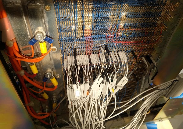
Most of the signals of interest are available on the Alto's backplane, which connects all the circuit cards. Since the backplane is wire-wrapped, it consists of pins that conveniently fit the logic analyzer probes. For each signal, you need to find the right card, and then count the pins until you find the right pin to attach the probe. This setup is very tedious, but Marc patiently connected all the probes, while Carl entered the configuration into the logic analyzer.

The backplane of the Xerox Alto, with probes from the logic analyzer attached to trace microcode execution. Note the thick power wires on the left.

The backplane of the Xerox Alto, with probes from the logic analyzer attached to trace microcode execution. Note the thick power wires on the left.

Unfortunately, a few important signals (the addresses of the micro-instructions) were not available on the backplane, and we needed to attach probes to one of the PROM chips that hold the microcode. Fortunately, the Living Computer Museum in Seattle gave us an extender card; by plugging the extender card into the backplane and the circuit board into the extender card, the board was accessible and we could connect the probes.

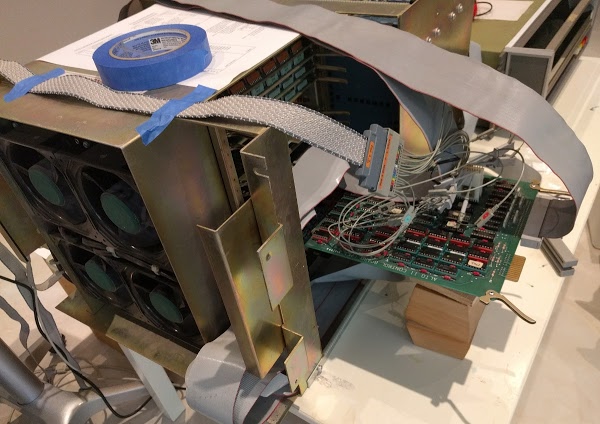
Logic analyzer hooked up to the Xerox Alto. By plugging the control board into an extension board, probes can be attached to it.

Probes from the logic analyzer hooked up to the Xerox Alto. By plugging the control board into an extension board, probes can be attached to it.

Hours later, with all the probes connected and the configuration programmed into the logic analyzer, we were ready to power up the system and collect data.

Running the logic analyzer

"Smoke! Stop! Shut it off!"

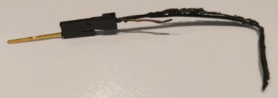
As soon as we flipped the power switch, smoke poured out of the backplane. Had we destroyed this rare computing artifact? What had gone wrong? When something starts smoking, it's usually pretty obvious where the problem is. In our case, one of the ground wires from the logic analyzer pod had melted, turning its insulation into smoke. A bit of discussion followed: "Pin 3 is ground, right?" "No, pin 9 is ground, pin 3 is 5 volts." "Oops." It turns out that when you short +5 and ground, a probe wire is no match for a 60 amp power supply. Fortunately, this wire was the only casualty of the mishap.

This logic probe wire melted when we accidentally connected +5 volts and ground with it.

This logic probe wire melted when we accidentally connected +5 volts and ground with it.

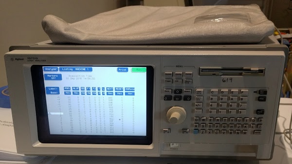
With this problem fixed, we were able to get a useful trace from the logic analyzer. The trace showed that the Alto started off with the emulator/boot task. After just four instructions, execution switched to the disk word task, which was rapidly interrupted by the parity error task. When that task finished, execution went back to the disk word task, which was interrupted a few instructions later by the display vertical task. The disk word task was able to run a few more instructions before the display horizontal task ran, followed by the cursor task.

The vintage Agilent 1670G logic analyzer that we connected to the Xerox Alto. The screen shows the start of the boot sequence.

The vintage Agilent 1670G logic analyzer that we connected to the Xerox Alto. The screen shows the start of the Alto's boot sequence.

It's rather amazing how much task switching is going on in the Alto, with low-priority tasks only getting a few instructions executed before being interrupted by a higher-priority task. Looking at the trace made me realize how much overhead these tasks have. In our case, the emulator task is running the boot code, so progress towards boot requires looking at hundreds of instructions in the logic analyzer.

The key thing we noticed in the traces is the parity error task ran right near the start, indicating an error in memory. This would explain why the system doesn't boot up. We ran a few more boot cycles through the logic analyzer. The specific order of tasks varied each time, as you'd expect since they are triggered asynchronously from hardware events. But we kept seeing the parity errors.

The Alto's memory system

The Alto was built in the early days of semiconductor memory, when RAM chips were expensive and unreliable. The original Alto module used Intel's 1103 memory chips, which were the first commercially available DRAM chip, holding just 1 kilobit. To provide 128 kilobytes of memory, the Alto I used 16 boards crammed full of chips. (If you're reading this on a computer with 4 gigabytes of memory, think about how much memory capacity has improved since the 1970s.)

We have the later Alto II XM (extended memory) system, which used more advanced 16 kilobit chips to fit 512 kilobytes of storage onto 4 boards. Each memory board stored a 10 bit chunk—why 10 bits? Because memory chips were unreliable, the Alto used error correction. To store a 32-bit word pair, 6 bits of Hamming error correction were added, along with a parity bit, and one unused bit. The extra bits allow single-bit errors to be corrected and double-bit errors to be detected. The four memory boards in parallel stored 40 bits at a time—the 32 bit word pair and the extra bits for error correction.

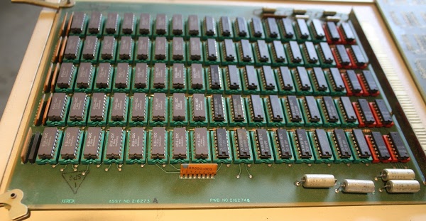
A 128KB memory card from the Xerox Alto.

A 128KB memory card from the Xerox Alto. The board has eighty 4116 DRAM chips, each with 16 kilobits of storage.

In addition to the 4 memory boards, the Alto has three circuit boards to control memory. The "MEAT" (Memory Extension And Terminator) is a trivial board to support four memory banks (the extended memory in the Alto XM). The "AIM" board (Address Interface Module) is a complex board that maps addresses to memory control signals, as well as handling memory-mapped peripherals such as the keyboard, mouse, and printer. Finally, the "DIM" board (Data Interface Module) generates the Hamming error correcting code signals, and performs error detection and correction.

More probing showed that the DIM board was always expressing a parity error. At this point, we're not sure if some of the memory chips are bad or if the complex circuitry on the DIM board is malfunctioning and reporting errors. As you can tell from the above description, the memory system on the Alto is complex. It may be a challenge to debug the memory and find out why we're getting errors.

A look at the microcode

In this section, I'll give a brief view of what the microcode looks like and how it appears in the logic analyzer. Microcode is generally hard to understand because it is at a very low level in the system, below the instruction set and running on the bare hardware. The Alto's microcode seems especially confusing.

Each Alto micro-instruction specifies an ALU operation and two "functions". A function can be something like "read a register" or "send an address to memory". But a function can also change meaning depending on what task is running. For instance, when the Ethernet task is running, a function might mean "do a four-way branch depending on the Ethernet state". But during the display task, the same function could mean "display these pixels on the screen". As a result, you can't figure out what an instruction does unless you know which task it is a part of.

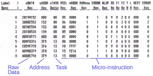
The image below shows a small part of the logic analyzer output (as printed on Marc's vintage HP line printer). Each line corresponds to one executed micro-instruction. The "address" column shows the address of the micro-instruction in the 1K PROM storage. The task field shows which task is running. You can see the task switch midway through execution; 0 is the emulator and 13 is the parity task. Finally, the 32-bit micro-instruction is broken into fields such as RSEL (register select), ALUF (ALU function) and F1 (function 1).

The start of the logic analyzer trace from booting the Xerox Alto. The trace shows us each micro-instruction that was executed.

The start of the logic analyzer trace from booting the Xerox Alto. The trace shows us each micro-instruction that was executed.

Note that the addresses jump around a lot; this is because the microcode isn't stored linearly in the PROM. Every micro-instruction has a "next instruction address" field in the instruction, so you can think of it as a GOTO inside every instruction. To make it worse, this field can be modified by the interface hardware, turning a GOTO into a computed GOTO. To make this work, the assembler shuffles instructions around in memory, so it's hard to figure out what code goes with a particular address. The point of this is that the logic analyzer output shows us every micro-instruction as it executes, but the output is somewhat difficult and tedious to interpret.

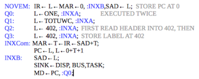
Fortunately we have the source code for the microcode, but understanding it is a challenge. The image below shows a small section of the boot code. I won't attempt to explain the microcode in detail, but want to give you a feel for what it is like. Labels (along the left) and jumps to labels are highlighted in blue. Things such as IR, L, and T are registers, and they get assigned values as indicated by the arrows. MAR is the memory address register (giving an address to memory) and MD is memory data, reading or writing the memory value.

A short section of the Xerox Alto's microcode. Labels and jumps are colored blue. Comments are gray.

A short section of the Xerox Alto's microcode. Labels and jumps are colored blue. Comments are gray.

Figuring out the control flow of the microcode requires detailed understanding of what is happening in the hardware. For example, in the last line above, ":Q0" indicates a jump to label "Q0". However the previous line says "BUS", which means the contents of the data bus are ORed into the address, turning the jump into a conditional jump to Q0, Q1, Q2, etc. depending on the bus value. And "TASK" indicates that a task switch can happen after the next instruction. So matching up the instructions in the logic analyzer output with instructions in the source code is non-trivial.

I should mention that the authors of the Alto's microcode were really amazing programers. An important feature for graphics displays is BITBLT, bit block transfer. The idea is to take an arbitrary rectangle of pixels in memory (such as a character, image, or window) and copy it onto the screen. The tricky part is that the regions may not be byte-aligned, so you may need to extract part of a byte, shift it over, and combine it with part of the destination byte. In addition, BITBLT supports multiple writing modes (copy, XOR, merge) and other features. So BITBLT is a difficult function to implement, even in a high-level language. The incredible part is that the Xerox Alto has BITBLT implemented in hundreds of lines of complex microcode! Using microcode for BITBLT made the operation considerably faster than implementing it in assembly code. (It also meant that BITBLT was used as a single machine language instruction.)

Conclusion

Hooking up the logic analyzer was time consuming, but succeeded in showing us exactly what was happening inside the Alto processor. Although interpreting the logic analyzer output and mapping it to the microcode source is difficult, we were able to follow the execution and determined that the parity task was running. It appears that memory parity errors are preventing the system from booting. Next step will be to understand the memory system in detail to determine where these errors are coming from and how to fix them.

Down to the silicon: how the Z80's registers are implemented

The 8-bit Z80 microprocessor is famed for use in many early personal computers such the Osborne 1, TRS-80, and Sinclair ZX Spectrum. The Z80 has an innovative design for its internal registers, with two sets of general-purpose registers. The diagram below shows a highly-magnified photo of the Z80 chip, from the Visual 6502 team. Zooming in on the register file at the right, the transistors that make up the registers are visible (with difficulty). Each register is in a column, with the low bit on top and high bit on the bottom. This article explains the details of the Z80's register structure: its architecture, how it works, and exactly how it is implemented, based on my reverse-engineering of the chip.
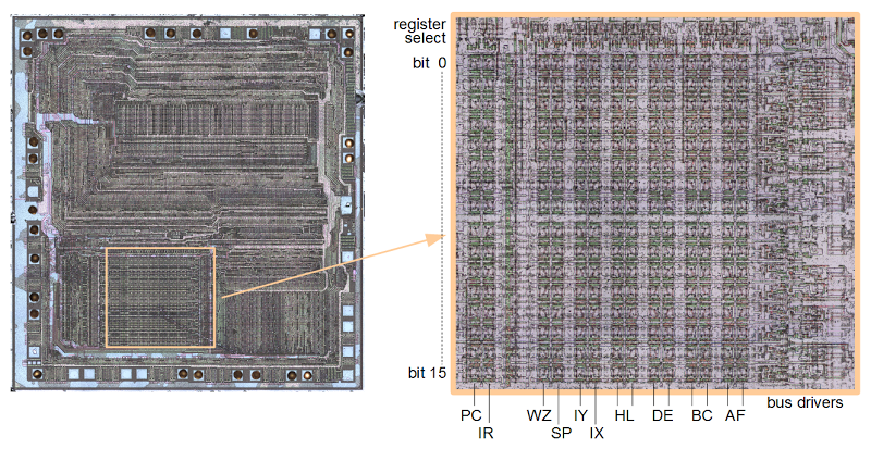
The die of the Z80 microprocessor, zooming in on the register file. Each register is stored vertically, with bit 0 and the top and bit 15 at the bottom. At the right, drivers connect the registers to the data buses. At the top, circuitry selects a register.

The die of the Z80 microprocessor, zooming in on the register file. Each register is stored vertically, with bit 0 and the top and bit 15 at the bottom. There are two sets of AF/BC/DE/HL registers. At the right, drivers connect the registers to the data buses. At the top, circuitry selects a register.

The Z80's architecture is often described with the diagram below, which shows the programmer's model of the chip.[1][2] But as we will see, the Z80's actual register and bus organization differs from this diagram in many ways. For instance, the data bus on the real chip has multiple segments. The diagram shows a separate incrementer for the refresh register (IR), an adder for IX and IY offsets, and a W'Z' register but those don't exist on the real chip. The Z80 shows that the physical implementation of a chip may be very different from how it appears logically.
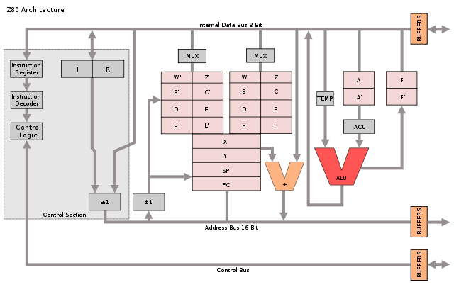
Programmer's model of Z80 architecture by Appaloosa. Licensed under CC BY-SA 3.0

Programmer's model of Z80 architecture from Wikipedia. Diagram by Appaloosa CC BY-SA 3.0. Original by Rodnay Zaks.

Register overview and layout

The diagram below shows how the Z80's registers are physically arranged on the chip, matching the die photo above. The register file consists of 14 pairs of 8-bit registers. In many cases, a pair of 8-bit registers is treated as a single 16-bit register. The bits are ordered from 0 at the top to 15 at the bottom, so the low-order byte is on the top and the high-order byte is on the bottom.

At the right of the register file are the 8-bit accumulator (A) and 8-bit flag register (F). The accumulator holds the result of arithmetic and logic operations, so it is a very important register. The flag register holds condition flags, for instance indicating a zero value, negative value, overflow value or other conditions.

Note that there are two A registers and two F registers, along with two of BC, DE, and HL. The Z80 is described as having a main register set (AF, BC, DE, and HL) and an alternate register set (A'F', B'C', D'E', and H'L'), and this is how the architecture diagram earlier is drawn. It turns out, though, that this is not how the Z80 is actually implemented. There isn't a main register set and an alternate register set. Instead, there are two of each register and either one can be the main or alternate. This will be explained in more detail below.

Structure of the Z-80's register file. The address is 16 bits wide, while the data buses are 8 bits wide. Gray lines show switches between bus segments.

Structure of the Z-80's register file as implemented on the chip. The address is 16 bits wide, while the data buses are 8 bits wide. Gray lines show switches between bus segments.

To the left of the AF registers are the two general-purpose BC registers. These can be used as 8-bit registers (B or C), or a 16-bit register (BC). Next to them are the similar DE and HL registers. The HL register is often used to reference a location in memory; H holds the high byte of the address, and L holds the low byte. This register structure is based on the earlier 8080 microprocessor. (As will be explained later, DE and HL can swap roles, so these registers should really be labeled H/D and L/E.)

Next to the left are the 16-bit IX and IY index registers. These are used to point to the start of a region in memory, such as a table of data. The 16-bit stack pointer SP is to the left of the index registers. The stack pointer indicates the top of the stack in memory. Data is pushed and popped from the stack, for instance in subroutine calls. To the left of the stack pointer are the 8-bit W and Z registers. As will be discussed below, these are internal registers used for temporary storage and are invisible to the programmer.

Separated from the previous registers is the special-purpose memory refresh register R, which simplifies the hardware when dynamic memory is used.[3] The interrupt page address register I is below R, and is used for interrupt handling. (It provides the high-order byte of an interrupt handler address.)

Finally, at the left is the 16-bit PC (Program Counter), which steps through memory to fetch instructions. Since it is 16 bits, the Z80 can address 64K of memory. Its position next to the incrementer/decrementer is important and will be discussed below.

The Z80's register buses

An important part of the Z80's architecture is how the registers are connected to other parts of the system by various buses. The Z80 is described as having a 16-bit address bus and an 8-bit data bus, but the implementation is more complicated.[3][4] The point of this complexity is to permit multiple register activities as the same time, so the chip can execute faster.

The PC and IR registers are separated from the rest of the registers. As the diagram above shows, these registers are connected to the other registers through a 16-bit bus (thick black line). However, this bus can be connected or disconnected as needed (by pass transistors indicated by the vertical gray line). When disconnected, the PC and R registers can be updated while registers on the right are in use.

The internal register bus connects the PC and IR registers to an incrementer/decrementer/latch circuit. It has multiple uses, but the main purpose is to step the PC from one instruction to the next, and to increment the R register to refresh memory. The resulting address goes to the address pins via the address bus (magenta). I describe the incrementer/decrementer/latch in detail here.

At the right, separate 8-bit data buses connect to the low-order and high-order registers. These two buses can be connected or disconnected as needed. The lower bus (orange) provides access to the ALU (arithmetic logic unit). The upper bus (green) connects to another data bus (red) that accesses the data pins and instruction decoder.
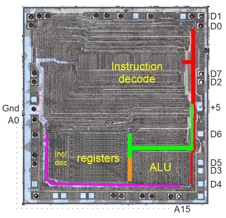
Photo of the Z80 die. The address bus is indicated in purple. The data bus segments are in red, green, and orange.

Photo of the Z80 die. The address bus is indicated in purple. The data bus segments are in red, green, and orange.

Specifying registers in the opcodes

The Z80 uses 8-bit opcodes to specify its instructions, and these instructions are carefully designed to efficiently specify which registers to use. Register instructions normally use three bits to specify the register used: 000=B, 001=C, 010=D, 011=E, 100=H, 101=L, 110=indirect through HL, 111=A.[5] For instance, the ADD instructions have the 8-bit binary values 10000rrr, where the rrr bits specify the register to use as above. Note that in this pattern the two high-order bits specify the register pair, while the low order bit specifies which half of the pair to use; for example 00x is BC, 000 is B, and 001 is C. For instructions operating on a register pair (such as 16-bit increment INC), the opcode uses just the two bits to specify the pair.

By using this structure for opcodes, the instruction decoding logic is simplified since the same circuitry can be reused to select a register or register pair for many different instructions. Instruction decode circuitry located above the register file uses the two bits to select the register pair and then uses the third bit to pick the lower or upper half of the register file.

The register selection bits can be in bits 2-0 of the instruction, for example AND; in bits 5-3 of the instruction, for example DEC (decrement); or in both positions, for example register-to-register LD.[6] To handle this, a multiplexer selects the appropriate group of bits and feeds them into the register select logic. Thus, the same circuit efficiently handles register bits in either position. By designing the instruction set in this way, the Z80 combines the ability to use a large register set with a compact hardware implementation.

Swapping registers through register renaming

The Z80 has several instructions to swap registers or register sets. The EX DE, HL instruction exchanges the DE and HL registers. The EX AF, AF' instruction exchanges the AF and AF' registers. The EXX instruction exchanges the BC, DE, and HL registers with the BC', DE', and HL' registers. These instructions complete very quickly, which raises the question of how multiple 16-bit register values can move around the chip at once.

It turns out that these instructions don't move anything. They just toggle a bit that renames the appropriate registers. For example, consider exchanging the DE and HL registers. If the DE/HL bit is set, an instruction acting on DE uses the first register and an instruction acting on HL uses the second register. If the bit is cleared, a DE instruction uses the second register and a HL instruction uses the first register. Thus, from the programmer's perspective, it looks like the values in the registers have been swapped, but in fact just the meanings/names/labels of the registers have been swapped. Likewise, a bit selects between AF and AF', and a bit selects between BC, DE, HL and the alternates. In all, there are four registers that can be used for DE or HL; physically there aren't separate DE and HL registers.

The hardware to implement register renaming is interesting, using four toggle flip flops.[7] These flip flops are toggled by the appropriate EX and EXX instructions. One flip flop handles AF/AF'. The second flip flop handles BC/DE/HL vs BC'/DE'/HL'. The last two flip flops handle DE vs HL and DE' vs HL'. Note that two flip flops are required since DE and HL can be swapped independently in either register bank.

The flags

The flags have a dual existence. The flags are stored inside the register file, but at the start of every instruction,[8] they are copied into latches above the ALU. From this location, the flags can be used and modified by the ALU. (For example, add or shift operations use the carry flag.) At the end of an instruction that affects flags, the flags are copied from the latches back to the register file.

Most of the flags are generated by the ALU (details here). The circuitry to set and use the carry is complicated, since it is used in different ways by shifts and rotates, as well as arithmetic. Conditional operations are another important use of the flags.[9]

The WZ temporary registers

The Z80 (like the 8080 and 8085) has a WZ register pair that is used for temporary storage but is invisible to the programmer. The primary use of WZ is to hold an operand from a two or three byte instruction until it can be used.[10]

The JP (jump) instruction shows why the WZ registers are necessary. This instruction reads a two-byte address following the opcode and jumps to that address. Since the Z80 only reads one byte at a time, the address bytes must be stored somewhere while being read in, before the jump takes place. (If you read the bytes directly into the program counter, you'd end up jumping to a half-old half-new address.) The WZ register pair is used to hold the target address as it gets read in. The CALL (subroutine call) instruction is similar.

Another example is EX (SP), HL which exchanges two bytes on the stack with the HL register. The WZ register pair holds the values at (SP+1) and (SP) temporarily during the exchange.

How the registers are implemented in silicon

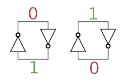
The building block for the registers is a simple circuit to store one bit, consisting of two inverters in a feedback loop. In the diagram below, if the top wire has a 0, the right inverter will output a 1 to the bottom wire. The left inverter will then output a 0 to the top wire, completing the cycle. Thus, the circuit is stable and will "remember" the 0. Likewise, if the top wire is a 1, this will get inverted to a 0 at the bottom wire, and back to a 1 at the top. Thus, this circuit can store either a 0 or a 1, forming a 1-bit memory.[11]

In the Z80, two coupled inverters hold a single bit in the register. This circuit is stable in either the 0 or 1 state.

In the Z80, two coupled inverters hold a single bit in the register. This circuit is stable in either the 0 or 1 state.

How does a value get stored into this inverter pair? Surprisingly, the Z80 just puts stronger signals on the wires, forcing the inverters to take the new values.[12] There's no logic involved, just "might makes right". (In contrast, the 6502 uses an additional transistor in the inverter feedback loop to break the feedback loop when writing a new value.)

To support multiple registers, each register bit is connected to bus lines by two pass transistors. These transistors act as switches that turn on to connect one register to the bus. Each register has a separate bus control signal, connecting the register to the bus when needed. Note that there are two bus lines for each bit - the value and its complement. As explained above, to write a new value to the bit, the new value is forced into the inverters. There are 16 pairs of bus lines running horizontally through the register file, one for each bit.
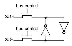
Each bit of register storage is connected to the bus by pass transistors, allowing the bit to be read or written.

Each bit of register storage is connected to the bus by pass transistors, allowing the bit to be read or written.

Next, to see how an inverter works, the schematic below shows how an inverter is implemented in the Z80. The Z80 uses NMOS transistors, which can be viewed as simple switches. If a 1 is input to the transistor's gate, the switch closes, connecting ground (0) to the output. If a 0 is input to the gate, the switch opens and the output is pulled high (1) by the resistor. Thus, the output is the opposite of the input.[13]
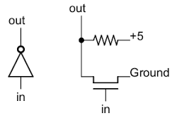
Implementation of an inverter in NMOS.

Implementation of an inverter in NMOS.

Putting this all together - the two inverters and the pass transistors - yields the following schematic for a single bit in the register file. The layout of the schematic matches the actual silicon where the inverters are positioned to minimize the space they take up. The bus lines and ground run horizontally. The control line to connect a register to the buses runs vertically, along with the 5V power line.
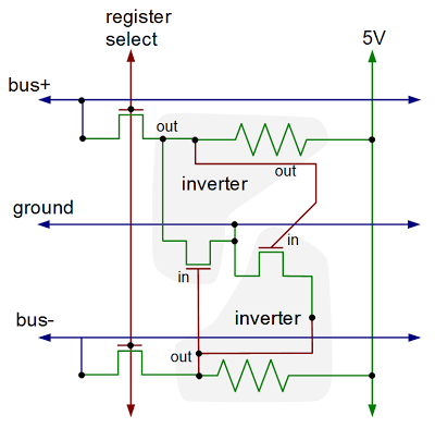
Schematic of one bit inside the Z80's register file.

Schematic of one bit inside the Z80's register file.

The diagram below shows the physical implementation of a register bit in the Z80, superimposed on a photo of the die. It's tricky to understand this, but comparing with the schematic above should help. The silicon is in green, the polysilicon is in red, and the metal lines are in blue. Transistors occur where the polysilicon (red) crosses the silicon (green). The X in a box indicates a contact connecting two layers. Note the large area taken up by the resistors (which are formed from depletion-mode transistors). Additional register bits can be seen in the photo, surrounding the bit illustrated.
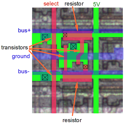
This diagram shows the layout on silicon of one bit of register storage. Green indicates silicon, red indicates polysilicon, and blue is the metal layer.

This diagram shows the layout on silicon of one bit of register storage. Green indicates silicon, red indicates polysilicon, and blue is the metal layer.

Zooming out, the picture below shows the upper right part of the register file. Each bit consists of a structure like the one above. Each column is a separate register, with a separate control line, and each row is one of the bits. The columns are in groups of two, with the register control lines between the pairs of columns. Zooming out more, the image at the top of the article shows the full register file and its location in the chip. Thus, you can see how the entire register file is built up from simple transistors.
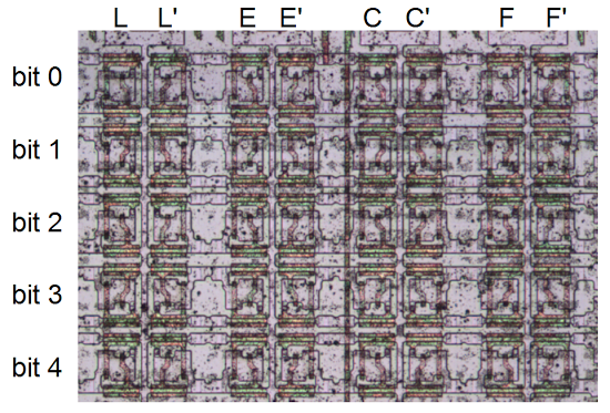
A detail of the Z80 chip, showing part of the register file.

A detail of the Z80 chip, showing part of the register file.

Comparison with the 6502 and 8085

While the Z80's register complement is tiny compared to current processors, it has a solid register set by 1976 standards - about twice as many registers as the 8085 and about four times as many registers as the 6502. Because they share the 8080 heritage, many of the 8085's registers are similar to the Z80, but the Z80 adds the IX and IY index registers, as well as the second set of registers.

The physical structure of the Z80's register file is similar to the 8085 register file. Both use 6-transistor static latches arranged into a 16-bit wide grid. The 8085, however, uses complex differential sense amplifiers to read the values from the registers. The Z80, by contrast, just uses regular gates. I suspect the 8085's designers saved space by making the register transistors as small as possible, requiring extra circuitry to read the weak values on the bus lines.

The 6502, on the other hand, doesn't have a separate register file. Instead, registers are put on the chip where it turns out to be convenient. Since the 6502 has fewer registers, the register circuitry doesn't need to be as optimized and each bit is more complex. The 6502 adds a transistor to each bit so it is clocked, and separate pass transistors for read and write. One consequence is direct register-to-register transfers are possible on the 6502, since the source and destination registers can be distinguished. Instead of a separate incrementer unit, the 6502's program counter is tangled in with the incrementer circuitry.

Conclusion

By looking at the silicon of the Z80 in detail, we can determine exactly how it works. The Z80's register file has more complexity than you'd expect and the hardware implementation is different from published architecture diagrams. By splitting the register file in two, the Z80 runs faster since registers can be updated in parallel. The Z80 includes a WZ register pair for temporary storage that isn't visible to the programmer. The Z80's register storage has many similarities to the 8085, both in the registers provided and their hardware implementation, but is very different from the 6502.

Credits: This couldn't have been done without the Visual 6502 team especially Chris Smith, Ed Spittles, Pavel Zima, Phil Mainwaring, and Julien Oster. All die photos are from the visual 6502 team.

Notes and references

[1] There are many variants of that architecture diagram; the one above is from Wikipedia. The original source of the common Z80 architecture diagram is the book Programming the Z80 by Rodnay Zaks, page 65 (HTML or PDF). The book is an extremely detailed guide to the Z80, down to the instruction cycles. I don't mean to criticize the architecture diagram by pointing out differences between it and the actual silicon. After all, it is a logic-level diagram intended for use by programmers, not a hardware reference. But it is interesting to see the differences between the programmer's view and the hardware implementation.

[2] Zilog's Z80 CPU user manual is a key reference on the instruction set and operation of the Z80, but it doesn't provide any information on the internal architecture.

[3] The Z80's memory refresh feature is described in patent 4332008. Figure 15 in the patent shows the segmented data bus used by the Z80, although it is a mirror image of the actual die.

[4] I wrote more about the data buses in the Z-80 in Why the Z-80's data pins are scrambled.

[5] The bit pattern 110 is an exception to the encoding of registers in instructions, since it refers to a memory location indexed by the HL register pair, rather than a register. Likewise the bit pattern 11x referring to a register pair is also an exception. It can indicate the SP register, for example in 16-bit LD, INC and DEC instructions.

[6] The Z80 specifies registers in instruction bits 0-2 and bits 3-5. This maps cleanly onto octal, but not hexadecimal. One consequence is the opcodes are more logical if you arrange them in octal (like this), instead of hexadecimal (like this). Perhaps the designers of the Z80 were thinking in octal and not hex.

[7] The toggle flip flops are unlike standard flip flops formed from gates. Instead they use pass transistors; this lets it hold the previous state while toggling to avoid oscillation. Because the pass transistor circuits depend on capacitance holding the values, you have to keep the clock running. This is one reason the clock in the Z80 can't stop for more than a couple microseconds. (The CMOS version is different and the clock can stop arbitrarily long.) From looking at the silicon, it appears that these flip flops required some modifications to work reliably, probably to ensure they toggled exactly once.

These flip flops have no reset logic, so it is unpredictable how the registers get assigned on power-up. Since there's no way to tell which register is which, this doesn't matter.

The active DE vs HL flip flop swaps the DE and HL register control lines using pass-gate multiplexers. The main vs alternate register set flip flops direct each AF/BC/DE/HL register control line to one of the two registers in the pair.

[8] Like many processors of its era, the Z80 starts fetching a new instruction before the previous instruction is finished; this is known as fetch/execute overlap. As a result, the flags are actually written from the latches to the register file three cycles into the next instruction (i.e. T3), and the flags are read from the register file into the latches four cycles into the instruction (i.e. T4).

[9] I'll explain briefly how conditional instructions such as jump (JP) work with the flags. Bits 4 and 5 of the opcode select the flag to use (via a multiplexer just to the right of the registers). Bit 3 of the opcode indicates the desired value (clear or set); this bit is XORed with the selected flag's value. The result indicates if the desired condition is satisfied or not, and is fed into the control logic to determine the appropriate action. The JR and DJNZ don't exactly fit the pattern so a couple additional gates adjust their bits to pick the right flags.

[10] For more explanation of the WZ registers, see Programming the Z80, pages 87-91.

[11] The register storage in the Z80 is called "static" memory, since it will store data as long as the circuit has power. In contrast, your computer uses dynamic memory, which will lose data in milliseconds if the data isn't constantly refreshed. The advantage of dynamic memory is it is much simpler (a transistor and a capacitor), and thus each cell is much smaller. (This is how DRAM can fit gigabits onto a single chip.) Another alternative is flash memory, which has the big advantage of keeping its contents while the power is turned off.

[12] If you've built electronic circuits, it may seem dodgy to force the inverters to change values by overpowering the outputs. But this is a standard technique in chips. To understand what happens, remember that in an NMOS circuit, a 0 output is created by a transistor to ground, while a 1 output is made by a much weaker resistor. So if one of the inverters is outputting a 1 and a 0 is connected to the output, the 0 will "win". This will cause the other inverter to immediately switch to 1. At this point, the original inverter will switch to output 0 and the inverter pair is now stable with the new values.

To improve speed, and to prevent a low voltage on the bus from accidentally clearing a bit while reading a register, the bus lines are all precharged to +5 every clock cycle. A low output from an inverter will have no trouble pulling the bus line low, and a high output will leave the bus line high. The precharging is done through transistors in the space between the IR and WZ registers.

[13] One disadvantage of NMOS logic is the pull-up resistors waste power. In addition, the output is fairly slow (by computer standards) to change from 0 to 1 because of the limited current through the resistor. For these, reasons, NMOS has been almost entirely replaced by CMOS logic which instead of resistors uses complementary transistors to pull the output high. (As a result, CMOS uses almost no power except while switching outputs from one state to another. For this reason, CMOS power usage scales up with frequency, which is why CPUs are hitting clock limits - they're too hot to run any faster.)

Four Rigol oscilloscope hacks with Python

A Rigol oscilloscope has a USB output, allowing you to control it with a computer and and perform additional processing externally. I was inspired by Cibo Mahto's article Controlling a Rigol oscilloscope using Linux and Python, and came up with some new Python oscilloscope hacks: super-zoomable graphs, generating a spectrogram, analyzing an IR signal, and dumping an oscilloscope trace as a WAV file. The key techniques I illustrate are connecting to the oscilloscope with Windows, accessing a megabyte of data with Long Memory, and performing analysis on the data.

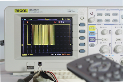
Analyzing the IR signal from a TV remote using an IR sensor and a Rigol DS1052E oscilloscope.

Analyzing the IR signal from a TV remote using an IR sensor and a Rigol DS1052E oscilloscope.

Super-zoomable graphs

One of the nice features of the Rigol is "Long Memory" - instead of downloading the 600-point trace that appears on the screen, you can record and access a high-resolution trace of 1 million points. In this hack, I show how you can display this data with Python, giving you a picture that you can easily zoom into with the mouse.

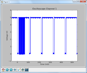
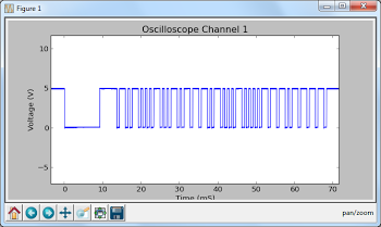
The following screenshot shows the data collected by hooking the oscilloscope up to an IR sensor. In the above picture, the sensor is the three-pin device below the screen. Since I've developed an IR library for Arduino, my examples focus on IR, but any sort of signal could be used. By enabling Long Memory, we can download not just the data on the screen, but 1 million data points, allowing us to zoom way, way in. The graph below shows what it sent when you press a button on the TV remote - the selected button transmits a code, followed by a periodic repeat signal as long as the button is held down.

The IR signal from a TV remote. The first block is the code, followed by period repeat signals while the button is held down.

The IR signal from a TV remote. The first block is the code, followed by period repeat signals while the button is held down.
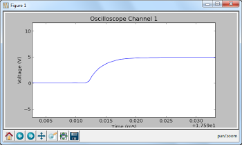
But with Long Memory, we can interactively zoom way on the waveform and see the actual structure of the code - long header pulses followed by a sequence of wide and narrow pulses that indicate the particular button. That's not the end of the zooming - we can zoom way in on an edge of a pulse and see the actual rise time of the signal over a few microseconds. You can do some pretty nice zooming when you have a million datapoints to plot.

Zooming in on the first part of the waveform shows the structure of the code - long header pulses followed by wide and narrow pulses. Zooming way, way in on the edge of a pulse shows the rise time of the signal.

To use this script, first enable Long Memory by going to Acquire: MemDepth. Next, set the trigger sweep to Single. Capture the desired waveform on the oscilloscope. Then run the Python script to upload the data to your computer, which will display a plot using matplotlib. To zoom, click the "+" icon at the bottom of the screen. This lets you pan back and forth through the data by holding down the left mouse button. You can zoom in and out by holding the right mouse button down and moving the mouse right or left. The magnifying glass icon lets you select a zoom rectangle with the mouse. You can zoom on your oscilloscope too, of course, but using a mouse and having labeled axes can be much more convenient.

A few things to notice about the code. The first few lines get the list of instruments connected to VISA and open the USB instrument (i.e. your oscilloscope). The timeout and chunk size need to be increased from the defaults to download the large amount of data without timeouts.

Next, ask_for_values gets various scale values from the oscilloscope so the axes can be labeled properly. By setting the mode to RAW we download the full dataset, not just what is visible on the screen. We get the raw data from channel 1 with :WAV:DATA? CHAN1. The first 10 bytes are a header and should be discarded. Next, the raw bytes are converted to numeric values with Mahto's formulas. Finally, matplotlib plots the data.

There are a couple "gotchas" with Long Memory. First, it only works reliably if you capture a single trace by setting the trigger sweep to "single". Second, downloading all this data over USB takes 10 seconds or so, which can be inconveniently slow.

Analyze an IR signal

Once we can download a signal from the oscilloscope, we can do more than just plot it - we can process and analyze it. In this hack, I decode the IR signal and print the corresponding hex value. Since it takes 10 seconds to download the signal, this isn't a practical way of using an IR remote for control. The point is to illustrate how you can perform logic analysis on the oscilloscope trace by using Python.

This code shows how the Python script can wait for the oscilloscope to be triggered and enter the STOP state. It also shows how you can use Python to initialize the oscilloscope to a desired configuration. The oscilloscope gets confused if you send too many commands at once, so I put a short delay between the commands.

Generate a spectrogram

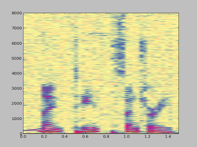
Another experiment I did was using Python libraries to generate a spectrogram of a signal recorded by the oscilloscope. I simply hooked a microphone to the oscilloscope, spoke a few words, and used the script below to analyze the signal. The spectrogram shows low frequencies at the bottom, high frequencies at the top, and time progresses left to right. This is basically a FFT swept through time.

A spectrogram generated by matplotlib using data from a Rigol DS1052E oscilloscope.

A spectrogram generated by matplotlib using data from a Rigol DS1052E oscilloscope.
To use this script, set up the oscilloscope for Long Memory as before, record the signal, and then run the script.

Dump data to a .wav file

You might want to analyze the oscilloscope trace with other tools, such as Audacity. By dumping the oscilloscope data into a WAV file, it can easily be read into other software. Or you can play the data and hear how it sounds.

To use this script, enable Long Memory as described above, capture the signal, and run the script. A file channel1.wav will be created.

How to install the necessary libraries

Before connecting your oscilloscope to your Windows computer, there are several software packages you'll need.
  • I assume you have Python already installed - I'm using 2.7.3.
  • Install NI-VISA Run-Time Engine 5.2. This is National Instruments Virtual Instrument Software Architecture, providing an interface to hardware test equipment.
  • Install PyVISA, the Python interface to VISA.
  • If you want to run the graphical programs, install Numpy and matplotlib.
You can also use Rigol's UltraScope for DS1000E software, but the included NI_VISA 4.3 software doesn't work with pyVisa - I ended up with VI_WARN_CONFIG_NLOADED errors. If you've already installed Ultrascope, you'll probably need to uninstall and reinstall NI_VISA.

If you're using Linux instead of Windows, see Mehta's article.

How to control and program the oscilloscope

Once the software is installed (below), connect the oscilloscope to the computer's USB port. Use the USB port on the back of the oscilloscope, not the flash drive port on the front panel.

Hopefully the code examples above are clear. First, the Python program must get the list of connected instruments from pyVisa and open the USB instrument, which will have a name like USB0::0x1AB1::0x0588::DS1ED141904883. Once the oscilloscope connection is open, you can use scope.write() to send a command to the oscilloscope, scope.ask() to send a command and read a result string, and scope.ask_for_values() to send a command and read a float back from the oscilloscope.

When the oscilloscope is under computer control, the screen shows Rmt and the front panel is non-responsive. The "Force" button will restore local control. Software can release the oscilloscope by sending the corresponding ":KEY:FORCE" command.

Error handling in pyVisa is minimal. If you send a bad command, it will hang and eventually timeout with VisaIOError: VI_ERROR_TMO: Timeout expired before operation completed.

The API to the oscilloscope is specified in the DS1000D/E Programming Guide. If you do any Rigol hacking, you'll definitely want to read this. Make sure you use the right programming guide for your oscilloscope model - other models have slightly different commands that seem plausible, but they will timeout if you try them.

Conclusions

Connecting an oscilloscope to a computer opens up many opportunities for processing the measurement data, and Python is a convenient language to do this. The Long Memory mode is especially useful, since it provides extremely detailed data samples.

64-bit RC6 codes, Arduino, and Xbox remotes

I've extended my Arduino IRremote library to support RC6 codes up to 64 bits long. Now your Arduino can control your Xbox by acting as an IR remote control. (The previous version of my library only supported 32 bit codes, so it didn't work with the 36-bit Xbox codes.) Details of the IRremote library are here.

Note: I don't actually have an Xbox to test this code with, so please let me know if the code works for you.

Download

This code is in my "experimental" branch since I'd like to get some testing before releasing it to the world. To use it:
  • Download the IRremote library zip file from GitHub from the Arduino-IRremote experimental branch.
  • Unzip the download
  • Move/rename the shirriff-Arduino-IRremote-nnnn directory to arduino-000nn/libraries/IRremote.

Sending an Xbox code

The following program simply turns the Xbox on, waits 10 seconds, turns it off, and repeats.
#include <IRremote.h>
IRsend irsend;
unsigned long long OnOff = 0xc800f740cLL;
int toggle = 0;

void sendOnOff() {
  if (toggle == 0) {
    irsend.sendRC6(OnOff, 36);
  } else {
    irsend.sendRC6(OnOff ^ 0x8000, 36);
  }
  toggle = 1 - toggle;
}
   
void setup() {}

void loop() {
  delay(10000);  // Wait 10 seconds
  sendOnOff();  // Send power signal
}
The first important thing to note is that the On/Off code is "unsigned long long", and the associated constant ends in "LL" to indicate that it is a long long. Because a regular long is only 32 bits, a 64-bit long long must be used to hold the 64 bit code. If you try using a regular long, you'll lose the top 4 bits ("C") from the code.

The second thing to notice is the toggle bit (which is explained in more detail below). Every time you send a RC5 or RC6 code, you must flip the toggle bit. Otherwise the receiver will ignore the code. If you want to send the code multiple times for reliability, don't flip the toggle bit until you're done.

Receiving an Xbox code

The following code will print a message on the serial console if it receives an Xbox power code. It will also dump the received value.
#include <IRremote.h>

int RECV_PIN = 11;
IRrecv irrecv(RECV_PIN);
decode_results results;

void setup()
{
  Serial.begin(9600);
  irrecv.enableIRIn(); // Start the receiver
}

void loop() {
  if (irrecv.decode(&results)) {
    if ((results.value & ~0x8000LL) == 0xc800f740cLL) {
      Serial.println("Got an OnOff code");
    }
    Serial.println(results.value >> 32, HEX);
    Serial.println(results.value, HEX);
    irrecv.resume(); // Receive the next value
  }
}
Two things to note in the above code. First, the received value is anded with ~0x8000LL; this clears out the toggle bit. Second, Serial.println is called twice, first to print the top 32 bits, and second to print the bottom 32 bits.

The output when sent power codes multiple times is:

Got an OnOff code
C
800FF40C
Got an OnOff code
C
800F740C
Got an OnOff code
C
...
Note that the received value is split between the two Serial.println calls. Also note that the output oscillates between ...F740C and ...FF40C as the sender flips the toggle bit. This is why the toggle bit must be cleared when looking for a particular value.

The IRremote/IRrecvDump example code has also been extended to display values up to 64 bits, and can be used for testing.

A quick description of RC6 codes

RC6 codes are somewhat more complicated than the usual IR code. They come in 20 or 36 bit varieties (that I know of). The code consists of a leader pulse, a start bit, and then the 20 (or 36) data bits. A 0 bit is sent as a space (off) followed by a mark (on), while a 1 bit is sent as a mark (on) followed by a space (off).

The first complication is the fourth data bit sent (called a trailer bit for some reason), is twice as long as the rest of the bits. The IRremote library handles this transparently.

The second complication is RC5 and RC6 codes use a "toggle bit" to distinguish between a button that is held down and a button that is pressed twice. While a button is held down, a code is sent. When the button is released and pressed a second time, a new code with one bit flipped is sent. On the third press, the original code is sent. When sending with the IRremote library, you must keep track of the toggle bit and flip it each time you send. When receiving with the IRremote library, you will receive one of two different codes, so you must clear out the toggle bit. (I would like the library to handle this transparently, but I haven't figured out a good way to do it.)

For details of the RC6 encoding with diagrams and timings, see SB projects.

The LIRC database

The LIRC project collects IR codes for many different remotes. If you want to use RC6 codes from LIRC, there a few things to know. A typical code is the Xbox360 file, excerpted below:
begin remote
  name  Microsoft_Xbox360
  bits           16
  flags RC6|CONST_LENGTH
  pre_data_bits   21
  pre_data       0x37FF0
  toggle_bit_mask 0x8000
  rc6_mask    0x100000000

      begin codes
          OpenClose                0x8BD7
          XboxFancyButton          0x0B9B
          OnOff                    0x8BF3
...
To use these RC6 code with the Arduino takes a bit of work. First, the codes have been split into 21 bits of pre-data, followed by 16 bits of data. So if you want the OnOff code, you need to concatenate the bits together, to get 37 bits: 0x37ff08bf3. The second factor is the Arduino library provides the first start bit automatically, so you only need to use 36 bits. The third issue is the LIRC files inconveniently have 0 and 1 bits swapped, so you'll need to invert the code. The result is the 36-bit code 0xc800f740c that can be used with the IRremote library.

The rc6_mask specifies which bit is the double-wide "trailer" bit, which is the fourth bit sent (both in 20 and 36 bit RC6 codes). The library handles this bit automatically, so you can ignore it.

The toggle_bit_mask is important, as it indicates which position needs to be toggled every other transmission. For example, to transmit OnOff you will send 0xc800f740c the first time, but the next time you will need to transmit 0xc800ff40c.

More details of the LIRC config file format are at WinLIRC.

Xbox codes

Based on the LIRC file, the following Xbox codes should work with my library:
OpenClose0xc800f7428XboxFancyButton0xc800ff464OnOff0xc800f740c
Stop0xc800ff419Pause0xc800f7418Rewind0xc800ff415
FastForward0xc800f7414Prev0xc800ff41bNext0xc800f741a
Play0xc800ff416Display0xc800f744fTitle0xc800ff451
DVD_Menu0xc800f7424Back0xc800ff423Info0xc800f740f
UpArrow0xc800ff41eLeftArrow0xc800f7420RightArrow0xc800ff421
DownArrow0xc800f741fOK0xc800ff422Y0xc800f7426
X0xc800ff468A0xc800f7466B0xc800ff425
ChUp0xc800f7412ChDown0xc800ff413VolDown0xc800ff411
VolUp0xc800ff410Mute0xc800ff40eStart0xc800ff40d
Play0xc800f7416Enter0xc800ff40bRecord0xc800f7417
Clear0xc800ff40a00xc800f740010xc800f7401
20xc800ff40230xc800f740340xc800ff404
50xc800f740560xc800ff40670xc800f7407
80xc800ff40890xc800f74091000xc800ff41d
Reload0xc800f741c

Key points for debugging

The following are the main things to remember when dealing with 36-bit RC6 codes:
  • Any 36-bit hex values must start with "0x" and end with "LL". If you get the error "integer constant is too large for 'long' type", you probably forgot the LL.
  • You must use "long long" or "unsigned long long" to hold 36-bit values.
  • Serial.print will not properly print 36-bit values; it will only print the lower 32 bits.
  • You must flip the toggle bit every other time when you send a RC6 code, or the receiver will ignore your code.
  • You will receive two different values for each button depending if the sender has flipped the toggle bit or not.