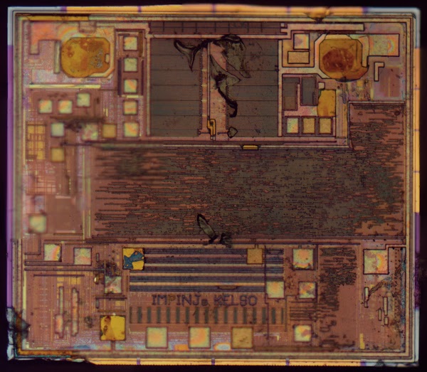
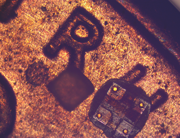
The die photo below shows the RFID chip used on these tags. To create it, I took 22 photos of the chip with my metallurgical microscope and stitched them together to create a high resolution photo. (Click the image for a larger version.) To prepare the chip, I removed it from the plastic carrier with Goof Off, dissolved the antenna with pool acid (HCl), and burnt off the mounting adhesive over a stove. This process left the chip visible with just a bit of debris that wouldn't come off. I'd probably get better results with boiling sulfuric acid, but that's too hazardous for me. I described the image stitching process in this article.
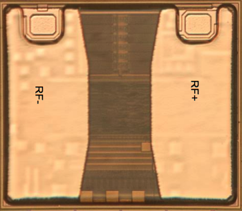
The chip turns out to be the Monza R6 RFID chip built by Impinj, a leading RFID chip company. The chip datasheet includes a die photo of the chip (below), but it is mostly obscured for some reason. Even so, it is clear that the chip in the datasheet matches the one I photographed.
How RFID timing works
The basic idea of RFID timing is the finish line has an RFID reader connected to a directional antenna. When the runner crosses the finish line, the reader communicates with the RFID chip on the runner's tag, determines the runner's ID number, and records the elapsed time.You might expect that the RFID chip simply returns the runner's number as the runner crosses the finish line, but there's a complex two-way protocol at work here. The chip uses the industry-standard EPC standard, and supports about a dozen commands: Select, Query, Read, Write, Lock, and various others. (While some RFID chips include cryptography, the R6 does not.) The chip receives commands from the reader and responds according to the protocol. The chip's memory includes an Electronic Product Code (EPC), which is a 96-bit universal identifier. In this case, the EPC value is returned to identify the runner.
One interesting thing is the RFID chip has no power source other than the radio signal; it is passive and doesn't need a battery. The reader transmits a radio signal (between 860 and 960 MHz), which is picked up by the antenna on the tag. The tiny amount of power received by the tag is what powers the RFID chip.
To send data to the RFID chip, the reader pulses the radio signal it emits. The chip detects these pulses and converts them into bits, using various modulation schemes (details). You might expect the chip transmits a radio signal to send data back to the reader, but it doesn't have enough power to do that. Instead, the chip dynamically changes load on the antenna (basically a transistor shorts out the antenna) while the reader is sending the radio signal. This causes a tiny change in the signal strength at the reader (about 1 part in 1000), which the reader can detect. This process, called backscatter, allows the chip to send data back to the reader without using power.
You might wonder how the system works if two runners cross the finish line at the same time—how do both tags get read without interference? RFID tags are designed for inventory systems, so they are designed to handle environments where there are hundreds of tags in range of the reader. They use an efficient anti-collision protocol. The reader can minimize collisions by querying a subset of tags at a time ("I only want to hear from tags whose ids start with 123.") By rapidly iterating through subsets, a large number of tags can be queried with minimal conflicts. Collisions are handled using a protocol called the Q-algorithm. Essentially, each tag waits a random amount before responding, so hopefully there won't be a collision. If there is a collision, tags wait a longer random amount next time until they can respond without collisions. This is based on the ALOHA protocol, which was also used to handle collisions on Ethernet networks.
Inside the chip
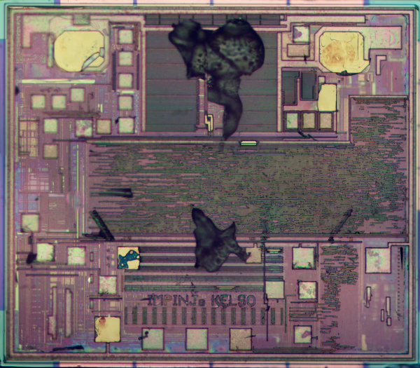
Below is another die photo. I took this one earlier in the cleaning process, so there is more debris on the chip surface. The colors are slightly different in this photo due to different microscope camera settings.
Because the chip is complex and has multiple layers of metal, I was unable to analyze its circuitry in detail. However, I can make some informed speculation about it. The top part of the chip is the analog circuitry, extracting power from the antenna, reading the transmitted signal, and modulating the return signal. The two antenna contacts are the large gold pads at the top (on the left and right). The rectangles between the antenna contacts are probably transistors and capacitors forming a charge pump to extract power from the radio signal (see patent). The voltage received from the radio signal is about 200 millivolts, while the chip's circuitry requires about 1 volt. The charge pump boosts the incoming voltage to the higher voltage required.
The middle of the chip has the logic circuitry. Given the complex protocol that the chip handles, you might expect a microprocessor to control the chip. But it uses a complex state machine instead, presumably to keep the chip small and reduce power consumption. This is probably build from CMOS standard digital logic cells, connected by the visible wiring (horizontal lines). This logic includes a pseudo-random number generator to support the anti-collision algorithm.
The chip has the label "IMPINJ KELSO". It's unclear why it is labeled "KELSO" and not "R6". I couldn't find any references to a "kelso" chip, so this could be an internal name. The Impinj company is in Seattle, Washington and Kelso is a small city in Washington, so perhaps that's the connection.
The bottom third of the chip likely contains the storage. The black rectangles above and below the IMPINJ KELSO text are probably the 12 bytes of non-volatile memory (NVM) that hold the tag identification. (This is essentially flash memory.) This Impinj patent discusses the NVM system. Writing the memory requires about 12 volts, which is provided by another charge pump. The gold squares scattered across the chip are probably test points used to program the chip and verify proper operation during manufacturing.
These chips are really small
Let me emphasize how tiny the RFID chips are—they are specks, about the size of a grain of salt. According to the datasheet, the chip is 464.1µm x 400µm (about 1/64 inch on a side). This is much smaller than a typical IC, and explains why the RFID chip doesn't break if the tag is flexed. The biggest problem I had with the die photos was making sure I didn't lose the chip. If I brushed against the chip it could stick to my finger and vanish until I carefully searched my hands to find it. The image below shows the Monza 4, a similar but slightly larger RFID chip, on top of a penny, next to a grain of salt. (A couple months ago, I wrote about the Monza 4 chip and how it is times the Bay to Breakers race.)
The antenna
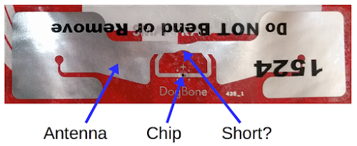
The antenna seems straightforward at first—two metal strips connected to the chip. But if you look more closely, you'll notice that the strips are joined together above the chip, which would short out the signal. How does this work? The short answer is it's RF magic. The longer answer is the antenna is carefully designed to match impedance between the transmitter and the chip, so as much power as possible is received by the chip. The central part of the antenna is the "loop" and the two long parts of the antenna are the "dipole". The loop doesn't short out the dipole, but instead they work together. The area of the loop acts as an antenna, and the dipole provides the appropriate impedance so the system resonates at the right frequency. The "dogbone" antenna shape isn't artistic but helps fit a longer dipole into the available area. RFID antennas are explained in more detail in this application note. The tag (combining the antenna and chip) is produced by Smartrac (whose name is barely visible under the black text), and sells for about 13 cents.
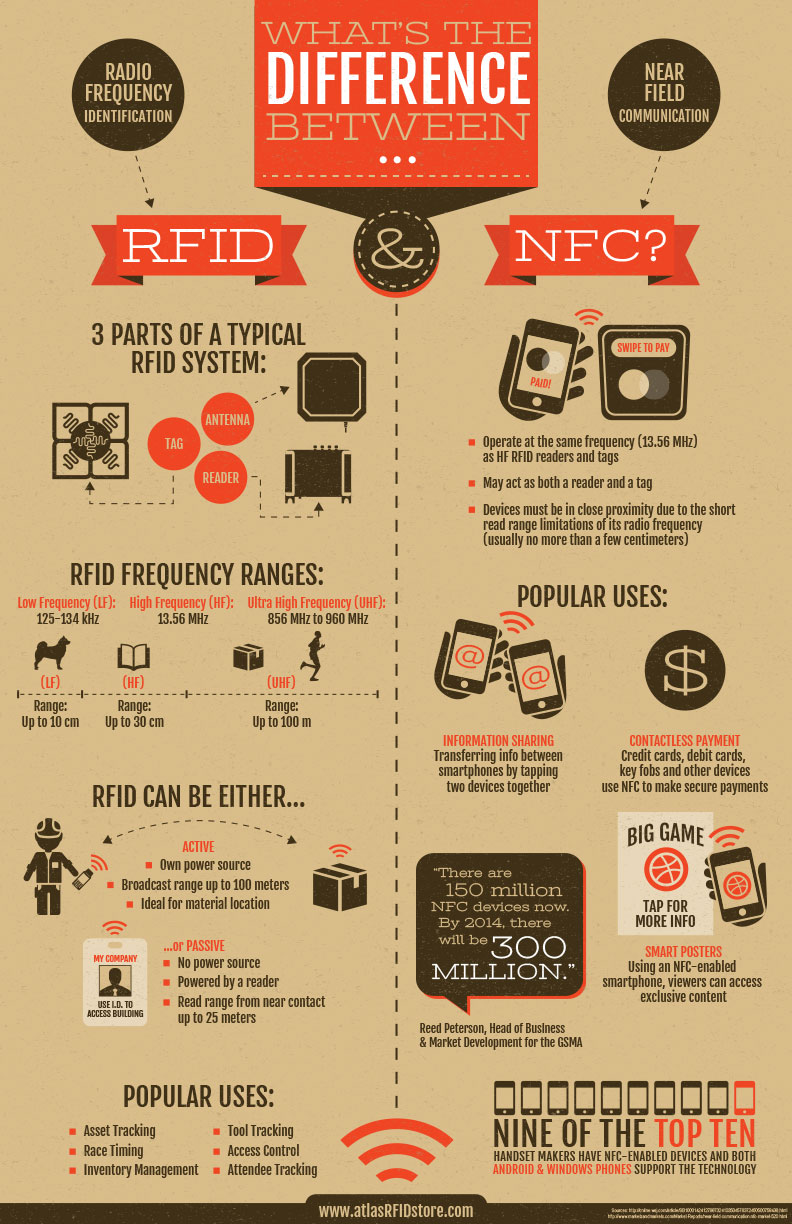
The RFID system is similar in some ways to the NFC (near-field communication) that smart phones use for tap-and-pay. The following infographic summarizes the differences (full size).
This infographic is courtesy of atlasRFIDstore.
Conclusion
The RFID chips used for race timing are very small but include a lot more complexity than you'd expect. I took some die photos of the Monza R6 chip that show the analog and digital circuitry crammed into a piece of silicon the size of a grain of salt. The chip manages to power itself off the radio signal, allowing it to operate without a battery. This circuitry supports a complex communication protocol between the RFID tag and the reader. The foil antenna is carefully designed to maximize power transfer to the chip. All this is combined into a tag that sells for under 13 cents.I announce my latest blog posts on Twitter, so follow me at kenshirriff.
