Like most microprocessors, the 8085 has a flag register that holds status information on the results of an operation. The flag register is 8 bits: bit 0 holds the carry flag, bit 2 holds the parity, bit 3 is always 0, bit 4 holds the half-carry, bit 6 holds the zero status, and bit 7 holds the sign. But what about the missing bits: 1 and 5?
Back in 1979, users of the 8085 determined that these flag bits had real functions.[1] Bit 1 is a signed-number overflow flag, called V, indicating that the result of a signed add or subtract won't fit in a byte.[2] Bit 5 of the flag is poorly understood and has been given the names K, X5, or UI. For an increment/decrement operation it simply indicates 16-bit overflow or underflow. But it has a totally diffrent value for arithmetic operations. The flag has been described[1][3] as:
As I will show, that published description is mistaken. The K flag actually is the V flag exclusive-ored with the sign of the result. And the purpose of the K flag is to compare signed numbers.K = O1·O2 + O1·R + O2·R, where: O1 = sign of operand 1 O2 = sign of operand 2 R = sign of result For subtraction and comparisons, replace O2 with complement of O2.
The circuit for the K and V flags
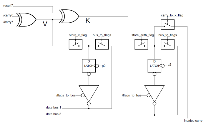
The following schematic shows the reverse-engineered circuit for the K and V flags in the 8085. The V flag is simply the exclusive-or of the carry into the top bit and the carry out of the top bit. This is a standard formula for computing overflow[2] for signed addition and subtraction. (The 6502 computes the same overflow value through different logic.) The V flag has values for other arithmetic operations, but the values aren't useful.[4] A latch stores the value of the V flag. The computed V value is stored in the latch under the control of a store_v_flag control signal. Alternatively, the flag value can be read off the bus and stored in the latch under the control of the bus_to_flags control signal; this is how the POP PSW instruction, which pops the flags from the stack, is implemented. Finally, a tri-state superbuffer (the large triangle) writes the flag value to the bus when needed.The K flag circuitry is on the right. The first function of the K flag is overflow/underflow for an INX/DEX instruction. This is implemented simply: the carry_to_k_flag control line sets the K flag according to the carry from the incrementer/decrementer. The next function of K flag is reading from the databus for the POP PSW instruction, which is the same as for the V flag. The final function of the K flag is the result of a signed comparison. The K flag is the exclusive-or of the V flag and the sign bit of the result. For subtraction and comparison, the K flag is 1 if the second value is larger than the first.[5] The K flag is set for other arithmetic operations, but doesn't have a useful value except for signed comparison and subtraction.[4]
From the circuit above, it is clear that the V and K flags were deliberately added to the chip. (This is in contrast to the 6502, where undocumented opcodes have arbitrary results due to how the circuitry just happens to work for unexpected inputs.[7]) Why would Intel add the above circuitry to the chip and then not document or support it? My theory is that Intel decided they didn't want to support K or (8-bit) V flags in the 8086, so in order to make the 8086 source-compatible with the 8085, they dropped those flags from the 8085 documentation, but the circuitry remained in the chip.
The silicon
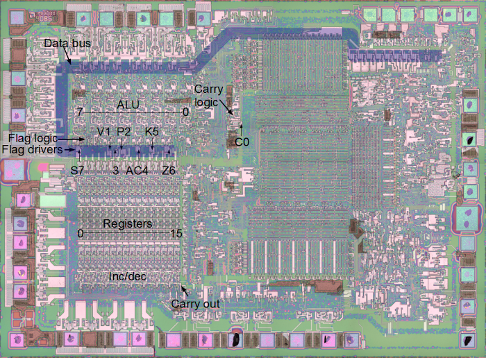
The flag logic circuitry sits underneath the ALU, with high-current drivers right on top of the data bus. The flags are arranged in apparently-random order with bit 7 (sign) on the left and bit 6 (zero) on the right. Because the carry logic is much more complicated (handling not only arithmetic operations but shifts and rotates, carry complement, and decimal adjust), the carry logic is stuck off to the right of the ALU where there was enough room.
Zooming in
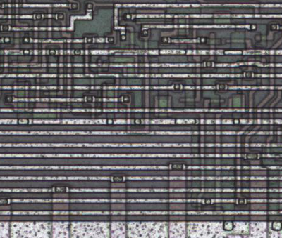
Next we will zoom in on the V flag circuitry, labeled V1 above. Looking at the die under a microscope shows the metal layer of the chip, consisting of mostly-horizontal metal interconnects, which are the white lines below. The bottom part of the chip has the 8-bit data bus. Other wires are the VCC power supply, ground, and a variety of signals. While modern processors can have ten or more metal layers, the 8085 only has a single layer. Some of the circuitry underneath the metal is visible.
MOSFET transistors
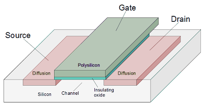
For this discussion, a MOSFET can be considered simply a switch that closes if the gate input is 1 and opens if the gate input is 0. A MOSFET transistor is implemented by separating two diffusion regions, and putting a polysilicon wire over the gate. An insulating layer prevents any current from flowing between the gate and the rest of the transistor. In the following diagram, the n+ diffusion regions are pink, the polysilicon gate conductor is dull green, and the insulating oxide layer is turquoise.NOR gate
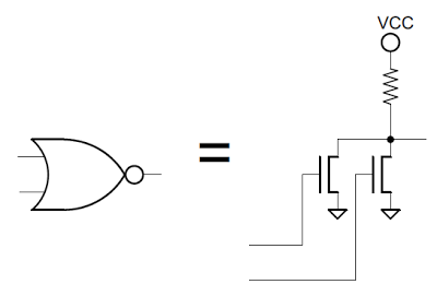
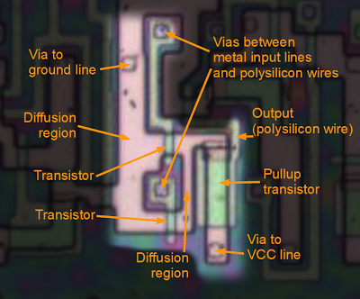
The NOR gate is a fundamental building block in the 8085, since it is a very simple gate that can form more complex logic. A NOR gate is implemented through two transistors and a pullup transistor. If either input (or both) is 1, the corresponding transistor connects the output to ground. Otherwise, the transistors are open, and the pullup pulls the output high. The pullup is shown as a resistor in the schematic, but it is actually a type of transistor called a depletion-mode transistor for better performance.By zooming in to a single NOR gate in the 8085, we can see how the gate is actually implemented. One surprise is that the circuit is almost all wiring; the transistors form a very small part of the circuit. The two transistors are connected to ground on the left, and tied together on the right. The pullup transistor is much larger than the other transistors for technical reasons.[8]
To understand the circuit, trace the path from ground to each transistor, across the gate, and to the output. In this way you can see there are two paths from ground to the output, and if either input is 1 the output will be 0.
The layout of the gate is intended to be as efficient as possible, given the constraints of where the power (VCC), ground, and other connections are, yielding a layout that looks a bit unusual. The power, ground, and input signals are all in the metal layer above (not shown here), and are connected to this circuit through vias between the metal and the silicon below.
Exclusive-or gates
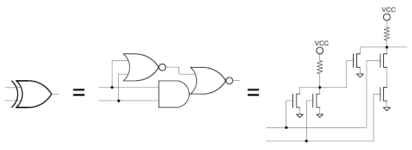
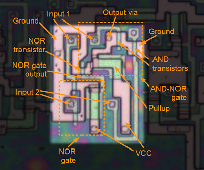
The exclusive-or circuit (which outputs a 1 if exactly one input is 1) is a key component of the flag circuitry, and illustrates how more complex logic can be formed out of simpler gates. The schematic below shows how the exclusive-or is built from a NOR gate and an AND-NOR gate; it is straightforward to verify that if both inputs are 0 or both inputs are 1, the output is will be 0.You may wonder why the 8085 uses so many "strange" gates such as a combined AND-NOR, instead of "normal" gates like AND. The transistor-level schematic shows that an AND-NOR gate can actually be implemented very simply with MOSFETs, in fact simpler than a plain AND gate. The two rightmost transistors form the "AND" - if they both have 1 inputs, they connect the output to ground. The transistor to the left forms the other part of the NOR - if it has a 1 input, it pulls the output to ground.
The following diagram shows an XOR circuit in the 8085 that matches the schematic above. (This is the XOR gate that generates the K flag.) On the left is the NOR gate discussed above, and on the right is the AND-NOR circuit, both outlined with a dotted line. As before, the circuit is mostly wiring, with the transistors forming a small part of the circuit (the green regions between pink diffusion regions).
The flag latch
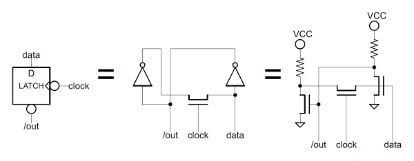
Each flag bit is stored in a simple latch circuit made up of two inverters. To store a 1, the inverter on the right outputs a 0, which is fed into the inverter on the left, which outputs a 1, which is fed back to the inverter on the right. A zero is stored in a similar (but opposite) manner. When the clock input is low, the pass transistor opens, breaking the feedback loop, and new data can be written into the latch. The complemented output (/out) is taken from the inverter.You might wonder why the latch doesn't lose its data whenever the clock goes low. There's an interesting trick here called dynamic logic. Because the gate of a MOSFET consists of an insulating layer it has very high resistance. Thus, any electrical charge on the gate will remain there for some time[9] when the pass transistor opens. When the pass transistor closes, the charge is refreshed.
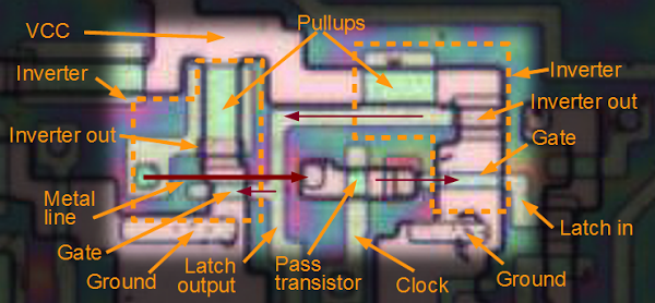
The following part of the 8085 chip shows the implementation of the latch for the V flag. The circuit closely matches the schematic above. The two inverters are outlined with dotted lines. The red arrows show the flow of data through the circuit. As before, the wiring and pullup transistors take up most of the silicon real estate.
Driving the data bus with a superbuffer
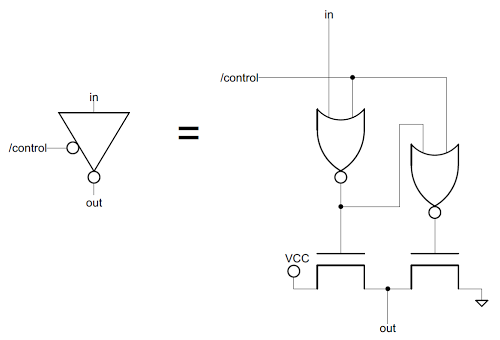
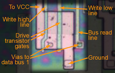
Another interesting feature of the flag circuit is the "superbuffer". Most transistors in the 8085 only send a signal a short distance. However, to send a signal on the data bus across the whole chip takes a lot more power, so a superbuffer is used. In the superbuffer, one transistor is driven to pull the output low, while a second transistor is driven to pull the output high. (This is in contrast to a regular gate, which uses a depletion-mode pullup transistor to pull the output high.) In addition, these transistors are considerably larger, to provide more current.[8] These two transistors are shown at the bottom the schematic below.The other feature of this superbuffer is that it is tri-state. In addition to a 0 or 1 output, it has a third state, which basically consists of providing no output. This way, the flags do not affect the data bus except when desired. In the schematic, it can be seen that if the control input is 1, both NOR gates will output 0, and both transistors will do nothing.
The following diagram shows the two drive transistors, as well as the line used to read the flag from the data bus. (The NOR gates are not shown.) Note the size of these transistors compared to transistors seen earlier. Each flag bit requires a superbuffer such as this. Even flag bit 3, which is always 0, requires a large transistor to drive the 0 onto the bus - it's surprising that a do-nothing flag still takes up a fair bit of silicon.
Putting it all together
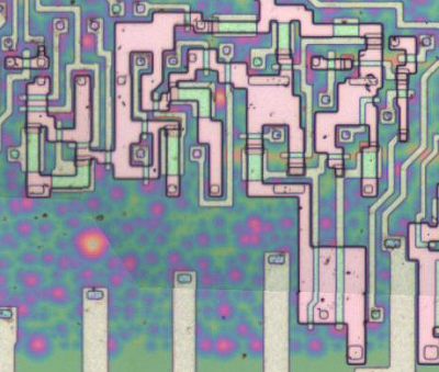
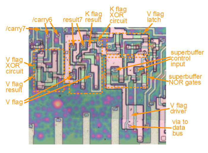
The above discussion has shown the details of the XOR gate that computes the K flag, and the latch and superbuffer for the V flag. The following diagram shows how these pieces fit into the overall circuitry. The latch and driver for the K flag are outside this image, to the right. The circuits below are tied together by the metal layer, which isn't shown. Compare this diagram with the schematic at the top of the article to see how the components are implemented. The two XOR circuits look totally different, since their layouts have been optimized to fit with the signals they need.
If you found this discussion interesting, check out my earlier analysis of the
6502's overflow flag and the 8085's ALU. You may also be interested in the book
The Elements of Computing Systems, which describes how to build a computer starting with Boolean logic.
Credits
The chip images are from visual6502.org. The visual6502 team did the hard work of dissolving chips in acid to remove the packaging and then taking many close-up photographs of the die inside. Pavel Zima converted these photographs into mask layer images, a transistor net, and an 8085 simulator.Notes and references
[1] The undocumented instructions and flags of the 8085 were discovered by Wolfgang Sehnhardt and Villy M. Sorensen in the process of writing an 8085 assembler, and were written up in the article Unspecified 8085 op codes enhance programming, Engineer's Notebook, "Electronics" magazine, Jan 18, 1979 p 144-145.
[2] See my article The 6502 overflow flag explained mathematically for details on overflow. There are multiple ways of computing overflow, and the 6502 uses a different technique.
[3] Tundra Semiconductor sold the CA80C85B, a CMOS version of the 8085. Interestingly, the undocumented opcodes and flags are described in the datasheet for this part: CA80C85B datasheet, 8000-series components.
The interesting thing about the Tundra datasheet is the descriptions of the "new" flags and instructions are copied almost exactly from Dehnhardt's article except for the introduction of errors, missing parentheses, and renaming the K flag as UI. In addition, as I described earlier, the published K/UI flag formula doesn't always work. Thus, it appears that despite manufacturing the chip, Tundra didn't actually know how these circuits worked.
[4] The V flag makes sense for signed addition and subtraction, and the K flag makes sense for signed subtraction and comparison. Many other operations affect these flags, but the flags may not have any useful meaning.
The V flag is 0 for RRC, RAR, AND, OR, and XOR operations, since these operations have constant carry values inside the ALU (details). The RLC and RAL operations add the accumulator to itself, so they can be treated the same as addition: V is set if the signed result is too big for a byte. The V flag for DAA can also be understood in terms of the underlying addition: V will only be set if the top digit goes from 7 to 8. However, since BCD digits are unsigned, V has no useful meaning with DAA. DAD is an interesting case, since the V flag indicates 16-bit signed overflow; it is actually computed from the result of the high-order addition. For INR, the only overflow case is going from 0x7f to 0x80 (127 to -128); note that going from 0xff to 0x00 corresponds to -1 to 0, which is not signed overflow even though it is unsigned overflow. Likewise, DCR sets the V flag going from hex 80 to 7f (-128 to 127); likewise 0x00 to 0xff is not signed overflow.
The K flag has a few special cases. For AND, OR, and XOR, the K flag is the same as the sign, since the V flag is 0. Note that the K flag is computed entirely differently for INR/DCR compared to INX/DCX. For INR and DCR, the K flag is S^V, which almost always is S. The K flag is set for DAA if S^V is true, which doesn't have any useful meaning since BCD values are unsigned.
The published formula for the K flag gives the wrong value for XOR if both arguments are negative.
[5] The following table illustrates the 8 possible cases when comparing signed numbers A and B. The inputs are the top bit of A, the top bit of B, and the carry from bit 6 when subtracting B from A. The outputs are the carry, borrow (complement of carry), sign, overflow, and K flags. An example is given for each row. Note that the K flag is set if A is less than B when treated as signed numbers.
| Inputs | Outputs | Example | |||||||
|---|---|---|---|---|---|---|---|---|---|
| A7 | B7 | C6 | C | B | S | V | K | Hex | Signed comparison |
| 0 | 1 | 0 | 0 | 1 | 0 | 0 | 0 | 0x50 - 0xf0 = 0x60 | 80 - -16 = 96 |
| 0 | 1 | 1 | 0 | 1 | 1 | 1 | 0 | 0x50 - 0xb0 = 0xa0 | 80 - -80 = -96 |
| 0 | 0 | 0 | 0 | 1 | 1 | 0 | 1 | 0x50 - 0x70 = 0xe0 | 80 - 112 = -32 |
| 0 | 0 | 1 | 1 | 0 | 0 | 0 | 0 | 0x50 - 0x30 = 0x120 | 80 - 48 = 32 |
| 1 | 1 | 0 | 0 | 1 | 1 | 0 | 1 | 0xd0 - 0xf0 = 0xe0 | -48 - -16 = -32 |
| 1 | 1 | 1 | 1 | 0 | 0 | 0 | 0 | 0xd0 - 0xb0 = 0x120 | -48 - -80 = 32 |
| 1 | 0 | 0 | 1 | 0 | 0 | 1 | 1 | 0xd0 - 0x70 = 0x160 | -48 - 112 = 96 |
| 1 | 0 | 1 | 1 | 0 | 1 | 0 | 1 | 0xd0 - 0x30 = 0x1a0 | -48 - 48 = -96 |
[6] A detailed explanation of signed comparisons is given in Beyond 8-bit Unsigned Comparisons by Bruce Clark, section 5. While this article is in the context of the 6502, the discussion applies equally to the 8085.
[7] The illegal opcodes in the 6502 are discussed in detail in How MOS 6502 Illegal Opcodes really work. In the 6502, the operations performed by illegal opcodes are unintended, just chance based on what the chip logic happens to do with unexpected inputs. In contrast, the undocumented opcodes in the 8085, like the undocumented flags, are deliberately implemented.
[8] The key parameter in the performance of a MOSFET transistor is the width to length ratio of the gate. Oversimplifying slightly, the current provided by the transistors is proportional to this ratio. (Width is the width of the source or drain, and length is the length across the gate from source to drain.) For an inverter, the W/L ratio of the pullup should be approximately 1/4 the W/L ratio of the input transistor for best performance. (See Introduction to VLSI Systems, Mead, Conway, p 8.) The result is that pullup transistors are big and blocky compared to pulldown transistors. Another consequence is that high-current transistors in a superbuffer have a very wide gate. The 8085 register file has some transistors where the W/L ratios are carefully configured so one transistor will "win" over the other if both are on at the same time. (This is why the 8085 simulator is more complex than the 6502 simulator, needing to take transistor sizes into account.)
[9] One effect of using pass-transistor dynamic buffers is that if the clock speed is too small, the charge will eventually drain away causing data loss. As a result the 8085 has a minimum clock speed of 500 kHz. Likewise, the 6502 has a minimum clock speed. The Z-80 in contrast is designed with static logic, so it has no minimum clock speed - the clock can be stepped as slowly as desired.
7 comments:
Wow... I guess I had forgotten that the 8085 didn't have a "jump if greater than" instruction like most of its contemporaries. I just went and looked at a couple 8085 instruction set summaries and sure enough, unless you include the undocumented instructions that test this flag, it's not there.
Other processors I've worked with from the time offer BGE/BLT that take (V xor S) to determine whether to branch, but they don't bother to store that as a discrete bit in the flags register. At least, the 6502, CP-1610 and 8086 take that approach.
if there're registers 0-8, isn't that 9 registers I think you miscounted somewhere.
Thanks, Anonymous; I've corrected that.
Very interesting information. I've heard that 8085 "undocumented" instructions and flags were not documented intentionally. These instructions didn't have matching instructions in the upcoming 8086 processor, which was supposed to be backward compatible with 8080 (and 8085). So if users were to use these instructions it would complicate porting programs to 8086.
It would be interesting to see similar information about 8086/88, and particularly if there are any differences between various 8086/8088/80C88 steppings or manufacturers.
Does anyone know why the pullup transistors are so big? I know that they need to have a big L/W ratio compared to the pulldown to give a good voltage transfer curve. (Though the NOR gate seems to have W_pulldown/L_pulldown/(W_pullup/L_pullup) = approx 6.5 which is a bit higher than the factor 4 derived in Mead & Conway - I wonder why?)
But what strikes me even more in this case is that all the pullups seem to have a width that is more than twice the minimum gate length, and they take up a lot of space on the die. Couldn't they have shrunk the pullups by a factor of 2 or at least 1.5 in both length and width, and saved a lot of space on the die?
I wonder if the pullups are actually using the minimum gate width, just that that is much bigger than the minimum gate length? They're not much wider than the pulldowns at least.
Or if it has something to do with that the pullups seem to be using buried contacts to connect the poly to the diffusion, where the buried contact is touching the pullup itself? Many other chips (6502, Z80 at least) seem to prefer to have the buried contact a little distance away, to improve manufacturing tolerances perhaps?
Excellent analysis, with one typo: Sehnhardt for Dehnhardt in note [1]
Post a Comment