Showing posts sorted by relevance for query z80. Sort by date Show all posts

Down to the silicon: how the Z80's registers are implemented

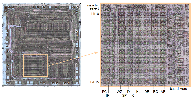
The 8-bit Z80 microprocessor is famed for use in many early personal computers such the Osborne 1, TRS-80, and Sinclair ZX Spectrum. The Z80 has an innovative design for its internal registers, with two sets of general-purpose registers. The diagram below shows a highly-magnified photo of the Z80 chip, from the Visual 6502 team. Zooming in on the register file at the right, the transistors that make up the registers are visible (with difficulty). Each register is in a column, with the low bit on top and high bit on the bottom. This article explains the details of the Z80's register structure: its architecture, how it works, and exactly how it is implemented, based on my reverse-engineering of the chip.

The die of the Z80 microprocessor, zooming in on the register file. Each register is stored vertically, with bit 0 and the top and bit 15 at the bottom. At the right, drivers connect the registers to the data buses. At the top, circuitry selects a register.

The die of the Z80 microprocessor, zooming in on the register file. Each register is stored vertically, with bit 0 and the top and bit 15 at the bottom. There are two sets of AF/BC/DE/HL registers. At the right, drivers connect the registers to the data buses. At the top, circuitry selects a register.

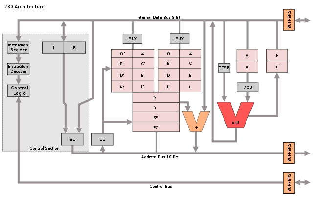
The Z80's architecture is often described with the diagram below, which shows the programmer's model of the chip.[1][2] But as we will see, the Z80's actual register and bus organization differs from this diagram in many ways. For instance, the data bus on the real chip has multiple segments. The diagram shows a separate incrementer for the refresh register (IR), an adder for IX and IY offsets, and a W'Z' register but those don't exist on the real chip. The Z80 shows that the physical implementation of a chip may be very different from how it appears logically.

Programmer's model of Z80 architecture by Appaloosa. Licensed under CC BY-SA 3.0

Programmer's model of Z80 architecture from Wikipedia. Diagram by Appaloosa CC BY-SA 3.0. Original by Rodnay Zaks.

Register overview and layout

The diagram below shows how the Z80's registers are physically arranged on the chip, matching the die photo above. The register file consists of 14 pairs of 8-bit registers. In many cases, a pair of 8-bit registers is treated as a single 16-bit register. The bits are ordered from 0 at the top to 15 at the bottom, so the low-order byte is on the top and the high-order byte is on the bottom.

At the right of the register file are the 8-bit accumulator (A) and 8-bit flag register (F). The accumulator holds the result of arithmetic and logic operations, so it is a very important register. The flag register holds condition flags, for instance indicating a zero value, negative value, overflow value or other conditions.

Note that there are two A registers and two F registers, along with two of BC, DE, and HL. The Z80 is described as having a main register set (AF, BC, DE, and HL) and an alternate register set (A'F', B'C', D'E', and H'L'), and this is how the architecture diagram earlier is drawn. It turns out, though, that this is not how the Z80 is actually implemented. There isn't a main register set and an alternate register set. Instead, there are two of each register and either one can be the main or alternate. This will be explained in more detail below.

Structure of the Z-80's register file. The address is 16 bits wide, while the data buses are 8 bits wide. Gray lines show switches between bus segments.

Structure of the Z-80's register file as implemented on the chip. The address is 16 bits wide, while the data buses are 8 bits wide. Gray lines show switches between bus segments.

To the left of the AF registers are the two general-purpose BC registers. These can be used as 8-bit registers (B or C), or a 16-bit register (BC). Next to them are the similar DE and HL registers. The HL register is often used to reference a location in memory; H holds the high byte of the address, and L holds the low byte. This register structure is based on the earlier 8080 microprocessor. (As will be explained later, DE and HL can swap roles, so these registers should really be labeled H/D and L/E.)

Next to the left are the 16-bit IX and IY index registers. These are used to point to the start of a region in memory, such as a table of data. The 16-bit stack pointer SP is to the left of the index registers. The stack pointer indicates the top of the stack in memory. Data is pushed and popped from the stack, for instance in subroutine calls. To the left of the stack pointer are the 8-bit W and Z registers. As will be discussed below, these are internal registers used for temporary storage and are invisible to the programmer.

Separated from the previous registers is the special-purpose memory refresh register R, which simplifies the hardware when dynamic memory is used.[3] The interrupt page address register I is below R, and is used for interrupt handling. (It provides the high-order byte of an interrupt handler address.)

Finally, at the left is the 16-bit PC (Program Counter), which steps through memory to fetch instructions. Since it is 16 bits, the Z80 can address 64K of memory. Its position next to the incrementer/decrementer is important and will be discussed below.

The Z80's register buses

An important part of the Z80's architecture is how the registers are connected to other parts of the system by various buses. The Z80 is described as having a 16-bit address bus and an 8-bit data bus, but the implementation is more complicated.[3][4] The point of this complexity is to permit multiple register activities as the same time, so the chip can execute faster.

The PC and IR registers are separated from the rest of the registers. As the diagram above shows, these registers are connected to the other registers through a 16-bit bus (thick black line). However, this bus can be connected or disconnected as needed (by pass transistors indicated by the vertical gray line). When disconnected, the PC and R registers can be updated while registers on the right are in use.

The internal register bus connects the PC and IR registers to an incrementer/decrementer/latch circuit. It has multiple uses, but the main purpose is to step the PC from one instruction to the next, and to increment the R register to refresh memory. The resulting address goes to the address pins via the address bus (magenta). I describe the incrementer/decrementer/latch in detail here.

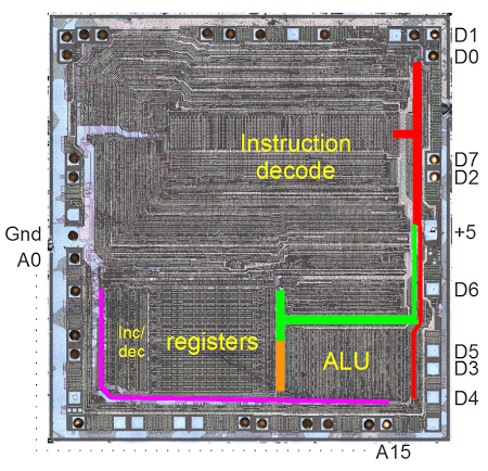
At the right, separate 8-bit data buses connect to the low-order and high-order registers. These two buses can be connected or disconnected as needed. The lower bus (orange) provides access to the ALU (arithmetic logic unit). The upper bus (green) connects to another data bus (red) that accesses the data pins and instruction decoder.

Photo of the Z80 die. The address bus is indicated in purple. The data bus segments are in red, green, and orange.

Photo of the Z80 die. The address bus is indicated in purple. The data bus segments are in red, green, and orange.

Specifying registers in the opcodes

The Z80 uses 8-bit opcodes to specify its instructions, and these instructions are carefully designed to efficiently specify which registers to use. Register instructions normally use three bits to specify the register used: 000=B, 001=C, 010=D, 011=E, 100=H, 101=L, 110=indirect through HL, 111=A.[5] For instance, the ADD instructions have the 8-bit binary values 10000rrr, where the rrr bits specify the register to use as above. Note that in this pattern the two high-order bits specify the register pair, while the low order bit specifies which half of the pair to use; for example 00x is BC, 000 is B, and 001 is C. For instructions operating on a register pair (such as 16-bit increment INC), the opcode uses just the two bits to specify the pair.

By using this structure for opcodes, the instruction decoding logic is simplified since the same circuitry can be reused to select a register or register pair for many different instructions. Instruction decode circuitry located above the register file uses the two bits to select the register pair and then uses the third bit to pick the lower or upper half of the register file.

The register selection bits can be in bits 2-0 of the instruction, for example AND; in bits 5-3 of the instruction, for example DEC (decrement); or in both positions, for example register-to-register LD.[6] To handle this, a multiplexer selects the appropriate group of bits and feeds them into the register select logic. Thus, the same circuit efficiently handles register bits in either position. By designing the instruction set in this way, the Z80 combines the ability to use a large register set with a compact hardware implementation.

Swapping registers through register renaming

The Z80 has several instructions to swap registers or register sets. The EX DE, HL instruction exchanges the DE and HL registers. The EX AF, AF' instruction exchanges the AF and AF' registers. The EXX instruction exchanges the BC, DE, and HL registers with the BC', DE', and HL' registers. These instructions complete very quickly, which raises the question of how multiple 16-bit register values can move around the chip at once.

It turns out that these instructions don't move anything. They just toggle a bit that renames the appropriate registers. For example, consider exchanging the DE and HL registers. If the DE/HL bit is set, an instruction acting on DE uses the first register and an instruction acting on HL uses the second register. If the bit is cleared, a DE instruction uses the second register and a HL instruction uses the first register. Thus, from the programmer's perspective, it looks like the values in the registers have been swapped, but in fact just the meanings/names/labels of the registers have been swapped. Likewise, a bit selects between AF and AF', and a bit selects between BC, DE, HL and the alternates. In all, there are four registers that can be used for DE or HL; physically there aren't separate DE and HL registers.

The hardware to implement register renaming is interesting, using four toggle flip flops.[7] These flip flops are toggled by the appropriate EX and EXX instructions. One flip flop handles AF/AF'. The second flip flop handles BC/DE/HL vs BC'/DE'/HL'. The last two flip flops handle DE vs HL and DE' vs HL'. Note that two flip flops are required since DE and HL can be swapped independently in either register bank.

The flags

The flags have a dual existence. The flags are stored inside the register file, but at the start of every instruction,[8] they are copied into latches above the ALU. From this location, the flags can be used and modified by the ALU. (For example, add or shift operations use the carry flag.) At the end of an instruction that affects flags, the flags are copied from the latches back to the register file.

Most of the flags are generated by the ALU (details here). The circuitry to set and use the carry is complicated, since it is used in different ways by shifts and rotates, as well as arithmetic. Conditional operations are another important use of the flags.[9]

The WZ temporary registers

The Z80 (like the 8080 and 8085) has a WZ register pair that is used for temporary storage but is invisible to the programmer. The primary use of WZ is to hold an operand from a two or three byte instruction until it can be used.[10]

The JP (jump) instruction shows why the WZ registers are necessary. This instruction reads a two-byte address following the opcode and jumps to that address. Since the Z80 only reads one byte at a time, the address bytes must be stored somewhere while being read in, before the jump takes place. (If you read the bytes directly into the program counter, you'd end up jumping to a half-old half-new address.) The WZ register pair is used to hold the target address as it gets read in. The CALL (subroutine call) instruction is similar.

Another example is EX (SP), HL which exchanges two bytes on the stack with the HL register. The WZ register pair holds the values at (SP+1) and (SP) temporarily during the exchange.

How the registers are implemented in silicon

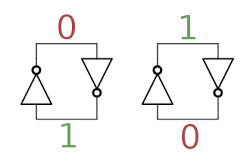
The building block for the registers is a simple circuit to store one bit, consisting of two inverters in a feedback loop. In the diagram below, if the top wire has a 0, the right inverter will output a 1 to the bottom wire. The left inverter will then output a 0 to the top wire, completing the cycle. Thus, the circuit is stable and will "remember" the 0. Likewise, if the top wire is a 1, this will get inverted to a 0 at the bottom wire, and back to a 1 at the top. Thus, this circuit can store either a 0 or a 1, forming a 1-bit memory.[11]

In the Z80, two coupled inverters hold a single bit in the register. This circuit is stable in either the 0 or 1 state.

In the Z80, two coupled inverters hold a single bit in the register. This circuit is stable in either the 0 or 1 state.

How does a value get stored into this inverter pair? Surprisingly, the Z80 just puts stronger signals on the wires, forcing the inverters to take the new values.[12] There's no logic involved, just "might makes right". (In contrast, the 6502 uses an additional transistor in the inverter feedback loop to break the feedback loop when writing a new value.)

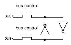
To support multiple registers, each register bit is connected to bus lines by two pass transistors. These transistors act as switches that turn on to connect one register to the bus. Each register has a separate bus control signal, connecting the register to the bus when needed. Note that there are two bus lines for each bit - the value and its complement. As explained above, to write a new value to the bit, the new value is forced into the inverters. There are 16 pairs of bus lines running horizontally through the register file, one for each bit.

Each bit of register storage is connected to the bus by pass transistors, allowing the bit to be read or written.

Each bit of register storage is connected to the bus by pass transistors, allowing the bit to be read or written.

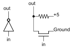
Next, to see how an inverter works, the schematic below shows how an inverter is implemented in the Z80. The Z80 uses NMOS transistors, which can be viewed as simple switches. If a 1 is input to the transistor's gate, the switch closes, connecting ground (0) to the output. If a 0 is input to the gate, the switch opens and the output is pulled high (1) by the resistor. Thus, the output is the opposite of the input.[13]

Implementation of an inverter in NMOS.

Implementation of an inverter in NMOS.

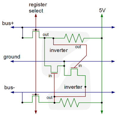
Putting this all together - the two inverters and the pass transistors - yields the following schematic for a single bit in the register file. The layout of the schematic matches the actual silicon where the inverters are positioned to minimize the space they take up. The bus lines and ground run horizontally. The control line to connect a register to the buses runs vertically, along with the 5V power line.

Schematic of one bit inside the Z80's register file.

Schematic of one bit inside the Z80's register file.

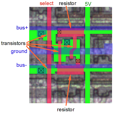
The diagram below shows the physical implementation of a register bit in the Z80, superimposed on a photo of the die. It's tricky to understand this, but comparing with the schematic above should help. The silicon is in green, the polysilicon is in red, and the metal lines are in blue. Transistors occur where the polysilicon (red) crosses the silicon (green). The X in a box indicates a contact connecting two layers. Note the large area taken up by the resistors (which are formed from depletion-mode transistors). Additional register bits can be seen in the photo, surrounding the bit illustrated.

This diagram shows the layout on silicon of one bit of register storage. Green indicates silicon, red indicates polysilicon, and blue is the metal layer.

This diagram shows the layout on silicon of one bit of register storage. Green indicates silicon, red indicates polysilicon, and blue is the metal layer.

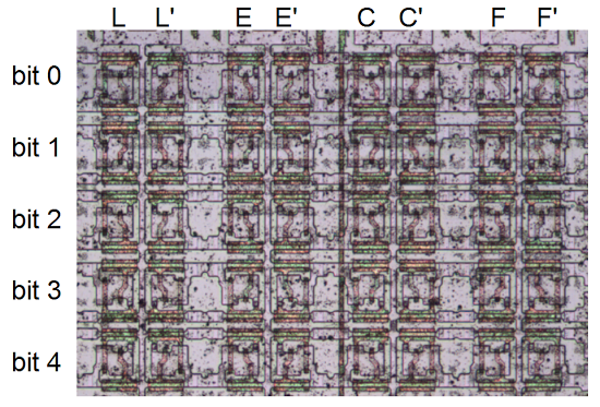
Zooming out, the picture below shows the upper right part of the register file. Each bit consists of a structure like the one above. Each column is a separate register, with a separate control line, and each row is one of the bits. The columns are in groups of two, with the register control lines between the pairs of columns. Zooming out more, the image at the top of the article shows the full register file and its location in the chip. Thus, you can see how the entire register file is built up from simple transistors.

A detail of the Z80 chip, showing part of the register file.

A detail of the Z80 chip, showing part of the register file.

Comparison with the 6502 and 8085

While the Z80's register complement is tiny compared to current processors, it has a solid register set by 1976 standards - about twice as many registers as the 8085 and about four times as many registers as the 6502. Because they share the 8080 heritage, many of the 8085's registers are similar to the Z80, but the Z80 adds the IX and IY index registers, as well as the second set of registers.

The physical structure of the Z80's register file is similar to the 8085 register file. Both use 6-transistor static latches arranged into a 16-bit wide grid. The 8085, however, uses complex differential sense amplifiers to read the values from the registers. The Z80, by contrast, just uses regular gates. I suspect the 8085's designers saved space by making the register transistors as small as possible, requiring extra circuitry to read the weak values on the bus lines.

The 6502, on the other hand, doesn't have a separate register file. Instead, registers are put on the chip where it turns out to be convenient. Since the 6502 has fewer registers, the register circuitry doesn't need to be as optimized and each bit is more complex. The 6502 adds a transistor to each bit so it is clocked, and separate pass transistors for read and write. One consequence is direct register-to-register transfers are possible on the 6502, since the source and destination registers can be distinguished. Instead of a separate incrementer unit, the 6502's program counter is tangled in with the incrementer circuitry.

Conclusion

By looking at the silicon of the Z80 in detail, we can determine exactly how it works. The Z80's register file has more complexity than you'd expect and the hardware implementation is different from published architecture diagrams. By splitting the register file in two, the Z80 runs faster since registers can be updated in parallel. The Z80 includes a WZ register pair for temporary storage that isn't visible to the programmer. The Z80's register storage has many similarities to the 8085, both in the registers provided and their hardware implementation, but is very different from the 6502.

Credits: This couldn't have been done without the Visual 6502 team especially Chris Smith, Ed Spittles, Pavel Zima, Phil Mainwaring, and Julien Oster. All die photos are from the visual 6502 team.

Notes and references

[1] There are many variants of that architecture diagram; the one above is from Wikipedia. The original source of the common Z80 architecture diagram is the book Programming the Z80 by Rodnay Zaks, page 65 (HTML or PDF). The book is an extremely detailed guide to the Z80, down to the instruction cycles. I don't mean to criticize the architecture diagram by pointing out differences between it and the actual silicon. After all, it is a logic-level diagram intended for use by programmers, not a hardware reference. But it is interesting to see the differences between the programmer's view and the hardware implementation.

[2] Zilog's Z80 CPU user manual is a key reference on the instruction set and operation of the Z80, but it doesn't provide any information on the internal architecture.

[3] The Z80's memory refresh feature is described in patent 4332008. Figure 15 in the patent shows the segmented data bus used by the Z80, although it is a mirror image of the actual die.

[4] I wrote more about the data buses in the Z-80 in Why the Z-80's data pins are scrambled.

[5] The bit pattern 110 is an exception to the encoding of registers in instructions, since it refers to a memory location indexed by the HL register pair, rather than a register. Likewise the bit pattern 11x referring to a register pair is also an exception. It can indicate the SP register, for example in 16-bit LD, INC and DEC instructions.

[6] The Z80 specifies registers in instruction bits 0-2 and bits 3-5. This maps cleanly onto octal, but not hexadecimal. One consequence is the opcodes are more logical if you arrange them in octal (like this), instead of hexadecimal (like this). Perhaps the designers of the Z80 were thinking in octal and not hex.

[7] The toggle flip flops are unlike standard flip flops formed from gates. Instead they use pass transistors; this lets it hold the previous state while toggling to avoid oscillation. Because the pass transistor circuits depend on capacitance holding the values, you have to keep the clock running. This is one reason the clock in the Z80 can't stop for more than a couple microseconds. (The CMOS version is different and the clock can stop arbitrarily long.) From looking at the silicon, it appears that these flip flops required some modifications to work reliably, probably to ensure they toggled exactly once.

These flip flops have no reset logic, so it is unpredictable how the registers get assigned on power-up. Since there's no way to tell which register is which, this doesn't matter.

The active DE vs HL flip flop swaps the DE and HL register control lines using pass-gate multiplexers. The main vs alternate register set flip flops direct each AF/BC/DE/HL register control line to one of the two registers in the pair.

[8] Like many processors of its era, the Z80 starts fetching a new instruction before the previous instruction is finished; this is known as fetch/execute overlap. As a result, the flags are actually written from the latches to the register file three cycles into the next instruction (i.e. T3), and the flags are read from the register file into the latches four cycles into the instruction (i.e. T4).

[9] I'll explain briefly how conditional instructions such as jump (JP) work with the flags. Bits 4 and 5 of the opcode select the flag to use (via a multiplexer just to the right of the registers). Bit 3 of the opcode indicates the desired value (clear or set); this bit is XORed with the selected flag's value. The result indicates if the desired condition is satisfied or not, and is fed into the control logic to determine the appropriate action. The JR and DJNZ don't exactly fit the pattern so a couple additional gates adjust their bits to pick the right flags.

[10] For more explanation of the WZ registers, see Programming the Z80, pages 87-91.

[11] The register storage in the Z80 is called "static" memory, since it will store data as long as the circuit has power. In contrast, your computer uses dynamic memory, which will lose data in milliseconds if the data isn't constantly refreshed. The advantage of dynamic memory is it is much simpler (a transistor and a capacitor), and thus each cell is much smaller. (This is how DRAM can fit gigabits onto a single chip.) Another alternative is flash memory, which has the big advantage of keeping its contents while the power is turned off.

[12] If you've built electronic circuits, it may seem dodgy to force the inverters to change values by overpowering the outputs. But this is a standard technique in chips. To understand what happens, remember that in an NMOS circuit, a 0 output is created by a transistor to ground, while a 1 output is made by a much weaker resistor. So if one of the inverters is outputting a 1 and a 0 is connected to the output, the 0 will "win". This will cause the other inverter to immediately switch to 1. At this point, the original inverter will switch to output 0 and the inverter pair is now stable with the new values.

To improve speed, and to prevent a low voltage on the bus from accidentally clearing a bit while reading a register, the bus lines are all precharged to +5 every clock cycle. A low output from an inverter will have no trouble pulling the bus line low, and a high output will leave the bus line high. The precharging is done through transistors in the space between the IR and WZ registers.

[13] One disadvantage of NMOS logic is the pull-up resistors waste power. In addition, the output is fairly slow (by computer standards) to change from 0 to 1 because of the limited current through the resistor. For these, reasons, NMOS has been almost entirely replaced by CMOS logic which instead of resistors uses complementary transistors to pull the output high. (As a result, CMOS uses almost no power except while switching outputs from one state to another. For this reason, CMOS power usage scales up with frequency, which is why CPUs are hitting clock limits - they're too hot to run any faster.)
Standard cells: Looking at individual gates in the Pentium processor

Intel released the powerful Pentium processor in 1993, a chip to "separate the really power-hungry folks from ordinary mortals." The original Pentium was followed by the Pentium Pro, the Pentium II, and others, spawning a long-running brand of high-performance processors, Intel's flagship line until the Core processors took over in 2006. The Pentium eventually became virtually synonymous with "PC" and even made it into pop culture.

Even though the Pentium is a complex chip with 3.3 million transistors, its transistors are visible under a microscope, unlike modern chips. By examining the chip, we can see the interesting circuits used for gates, flip-flops, and other circuits, including the use of an unusual technology called BiCMOS. In this article, I take a close look at the original Pentium chip1, showing how much of its circuitry was built out of structured rows of tiny transistors, a technique known as standard-cell design.

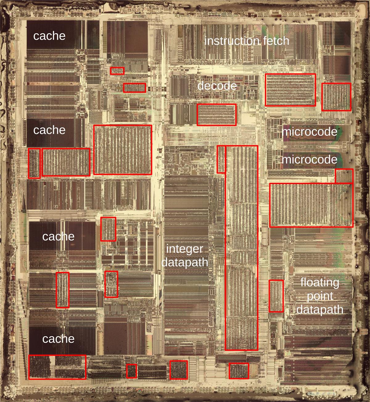
The die photo below shows the Pentium's fingernail-sized silicon die under a microscope. I removed the chip's four metal layers to show the underlying silicon, revealing the individual transistors, which are obscured in most die photos by the layers of metal. Standard-cell circuitry, indicated by red boxes, is recognizable because the circuitry is arranged in uniform columns of cells, giving it a characteristic striped appearance. In contrast, the chip's manually-optimized functional blocks are denser and more structured, giving them a darker appearance. Examples are the caches on the left, the datapaths in the middle, and the microcode ROMs on the right.

Die photo of the Intel Pentium processor with standard cells highlighted in red. The edges of the chip suffered some damage when I removed the metal layers. Click this image (or any other) for a larger version.

Die photo of the Intel Pentium processor with standard cells highlighted in red. The edges of the chip suffered some damage when I removed the metal layers. Click this image (or any other) for a larger version.

Standard-cell design

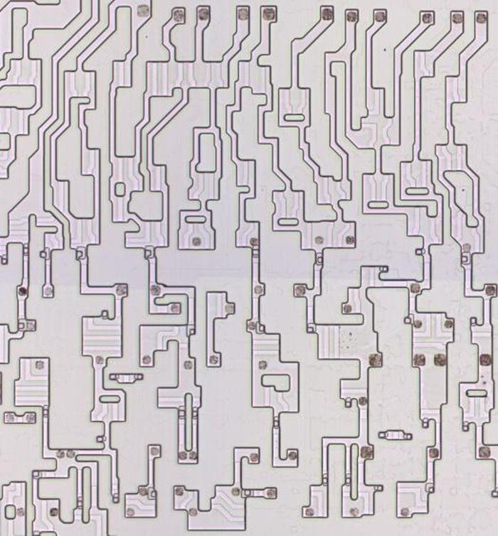
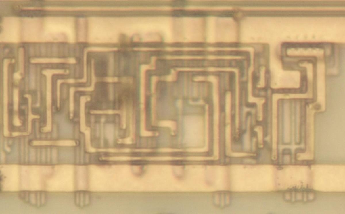
Early processors in the 1970s were usually designed by manually laying out every transistor individually, fitting transistors together like puzzle pieces to optimize their layout. While this was tedious, it resulted in a highly dense layout. Federico Faggin, designer of the popular Z80 processor, was almost done when he ran into a problem. The last few transistors wouldn't fit, so he had to erase three weeks of work and start over. The closeup of the resulting Z80 layout below shows that each transistor has a different, complex shape, optimized to pack the transistors as tightly as possible.2

A closeup of transistors in the Zilog Z80 processor (1976). This chip is NMOS, not CMOS, which provides more layout flexibility. The metal and polysilicon layers have been removed to expose the underlying silicon. The lighter stripes over active silicon indicate where the polysilicon gates were. I think this photo is from the Visual 6502 project but I'm not sure.

A closeup of transistors in the Zilog Z80 processor (1976). This chip is NMOS, not CMOS, which provides more layout flexibility. The metal and polysilicon layers have been removed to expose the underlying silicon. The lighter stripes over active silicon indicate where the polysilicon gates were. I think this photo is from the Visual 6502 project but I'm not sure.

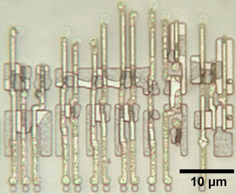
Because manual layout is slow, difficult, and error-prone, people developed automated approaches such as standard-cell.3 The idea behind standard-cell is to create a standard library of blocks (cells) to implement each type of gate, flip-flop, and other low-level component. To use a particular circuit, instead of arranging each transistor, you use the standard design from the library. Each cell has a fixed height but the width varies as needed, so the standard cells can be arranged in rows. The Pentium die photo below shows seven cells in a row. (The rectangular blobs are doped silicon while the long, thin vertical lines are polysilicon.) Compare the orderly arrangement of these transistors with the Z80 transistors above.

Some standard cell circuitry in the Pentium.
I removed the metal to show the underlying silicon and polysilicon.

Some standard cell circuitry in the Pentium. I removed the metal to show the underlying silicon and polysilicon.

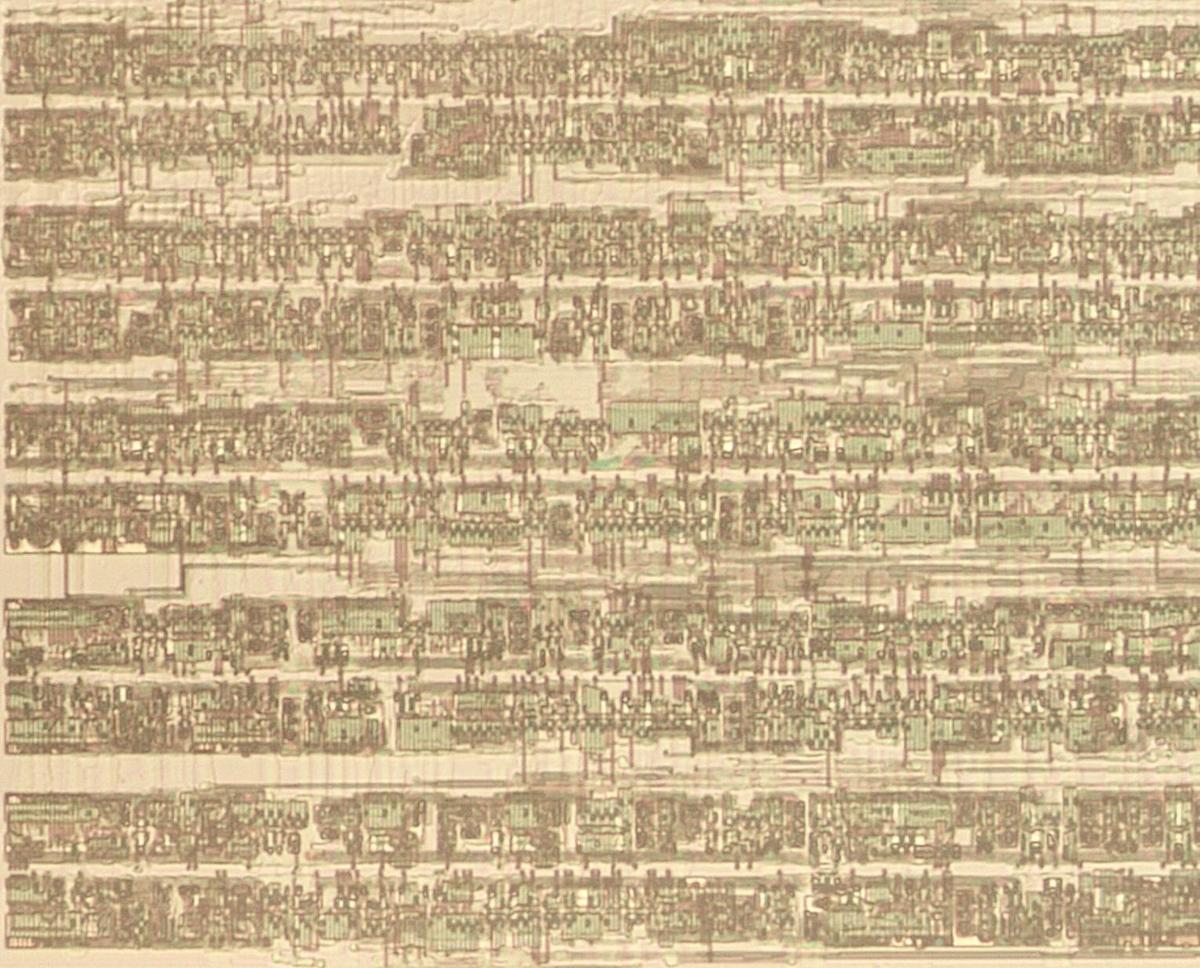
The photo below zooms out to show five rows of standard cells (the dark bands) and the wiring in between. Because CMOS circuitry uses two types of transistors (NMOS and PMOS), each standard-cell row appears as two closely-spaced bands: one of NMOS transistors and one of PMOS transistors. The space between rows is used as a "wiring channel" that holds the wiring between the cells. Power and ground for the circuitry run along the top and bottom of each row.
Some standard cells in the Pentium processor.

Some standard cells in the Pentium processor.

The fixed structure of standard cell design makes it suitable for automation, with the layout generated by "automatic place and route" software. The first step, placement, consists of determining an arrangement of cells that minimizes the distance between connected cells. Running long wires between cells wastes space on the die, since you end up with a lot of unnecessary metal wiring. But more importantly, long paths have higher capacitance, slowing down the signals. Once the cells are placed in their positions, the "routing" step generates the wiring to connect the calls. Placement and routing are both difficult optimization problems that are NP-complete.

Intel started using automated place and route techniques for the 386 processor, since it was much faster than manual layout and dramatically reduced the number of errors. Placement was done with a program called Timberwolf, developed by a Berkeley grad student. As one member of the 386 team said, "If management had known that we were using a tool by some grad student as a key part of the methodology, they would never have let us use it." Intel developed custom software for routing, using an iterative heuristic approach. Standard-cell design is still used in current processors, but the software is much more advanced.

A brief overview of CMOS

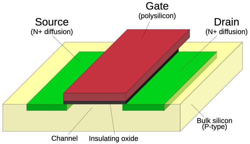
Before looking at the standard cell circuits in detail, I'll give a quick overview of how CMOS circuits are implemented. Modern processors are built from CMOS circuitry, which uses two types of transistors: NMOS and PMOS. The diagram below shows how an NMOS transistor is constructed. The transistor can be considered a switch between the source and drain, controlled by the gate. The source and drain regions (green) consist of silicon doped with impurities to change its semiconductor properties, forming N+ silicon. The gate consists of a layer of polysilicon (red), separated from the silicon by a very thin insulating oxide layer. Whenever polysilicon crosses active silicon, a transistor is formed. Diagram showing the structure of an NMOS transistor.

Diagram showing the structure of an NMOS transistor.

The NMOS and PMOS transistors are opposite in their construction and operation. A PMOS transistor swaps the N-type and P-type silicon, so it consists of P+ regions in a substrate of N silicon. In operation, an NMOS transistor turns on when the gate is high, while a PMOS transistor turns on when the gate is low.4 An NMOS transistor is best at pulling its output low, while a PMOS transistor is best at pulling its output high. In a CMOS circuit, the transistors work as a team, pulling the output high or low as needed; the "C" in CMOS indicates this "Complementary" approach. NMOS and PMOS transistors are not entirely symmetrical, however, due to the underlying semiconductor physics. Instead, PMOS transistors need to be larger than NMOS transistors, which helps to distinguish PMOS transistors from NMOS transistors on the die.

The layers of circuitry in the Pentium

The construction of the Pentium is more complicated than the diagram above, with four layers of metal wiring that connect the transistors.5 Starting at the surface of the silicon die, the Pentium's transistors are similar to the diagram, with regions of silicon doped to change their semiconductor properties. Polysilicon wiring is created on top of the silicon. The most important role of the polysilicon is that when it crosses doped silicon, a transistor is formed, with the polysilicon as the gate. However, polysilicon is also used as wiring over short distances.

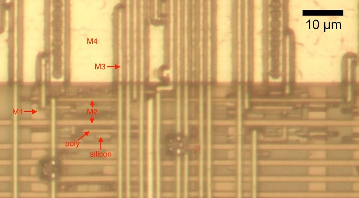
Above the silicon, four layers of metal connect the components: multiple metal layers allow signals to crisscross the chip without running into each other. The metal layers are numbered M1 through M4, with M1 on the bottom. A few rules control the wiring: a metal layer can connect with the layer above or below through a tungsten plug called a "via". Only the bottom metal, M1, can connect to the silicon or polysilicon, through a "contact". The layers usually alternate between horizontal wiring and vertical wiring (at least locally). Thus, a signal from a transistor may travel through M1, bounce up to M2 and M3 to cross other signals, and then go back down to M1 to connect to another transistor. As you can see, automated place and route software has a complicated task, producing millions of complicated wiring paths as densely as possible.

The diagram below shows how the layers appear on the chip. (This photo shows one of the rare spots on the chip where all the layers are visible.) The M4 metal layer on top of the chip is the thickest, so it is mostly used for power, ground, and clock signals rather than data. An M4 ground wire covers the top of this photo. The next layer down is M3. In this part of the chip, M3 lines run vertically. (Due to optical effects, the vertical M3 lines may look like they are on top of M4, but they are below.) The horizontal M2 metal lines are lower and appear brown rather than golden, due to the oxide layers that cover them. The bottom metal layer is M1. The vertical M1 lines are thick in this part of the chip because they provide power to the circuitry.

The Pentium is constructed with four layers of metal. Because the chip has a three-dimensional structure, I used focus stacking to get a clearer image.

The Pentium is constructed with four layers of metal. Because the chip has a three-dimensional structure, I used focus stacking to get a clearer image.

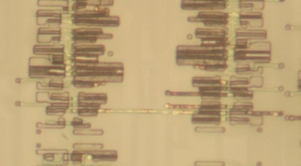
The silicon and polysilicon are mostly obscured in the above photo. By removing all the metal layers, I obtained the image below. This image shows the same region as the image above, but it is hard to see the correlation because the metal layers almost completely obscure the silicon. The orderly columns of transistors reveal the standard-cell design. The irregular dark regions are doped silicon, which forms the chip's transistors. The dark or shiny horizontal bands are polysilicon. I will explain below how these regions form gates and other circuits.

A closeup of the silicon and polysilicon.

A closeup of the silicon and polysilicon.

Inverter

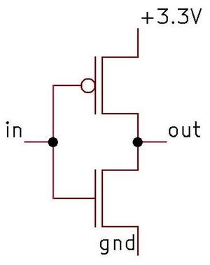
The fundamental CMOS gate is an inverter, shown in the schematic below. The inverter is built from one PMOS transistor (top) and one NMOS transistor (bottom). If the gate input is a "1", the bottom transistor turns on, pulling the output to ground (0). A "0" input turns on the top transistor, pulling the output high (1). Thus, this two-transistor circuit implements an inverter.10

Schematic diagram of a CMOS inverter.

Schematic diagram of a CMOS inverter.

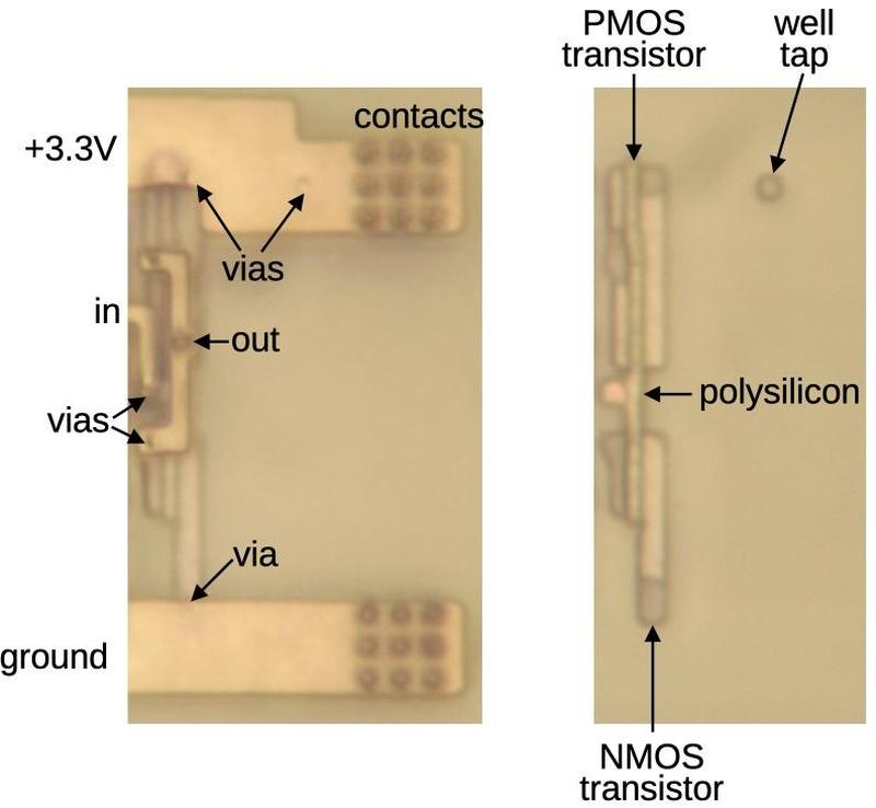
The diagram below shows two views of how a standard-cell inverter appears on the Pentium die, with and without metal. The inverter consists of two transistors, just like the schematic above. The input is connected to the two polysilicon gates of the transistors. The metal output wire is connected to the two transistors (the left sides, specifically).

A standard-cell CMOS inverter in the Pentium.

A standard-cell CMOS inverter in the Pentium.

In more detail, the image on the left includes the bottom (M1) metal layer, but I removed the other metal layers. Two thick metal lines at the top and bottom provide power and ground to the standard cells. The multiple dark circles are contacts between the M1 metal layer and the metal layer on top (M2), providing a path for power and ground that eventually reaches the top (M4) metal layer and then the chip's pins. (The power and ground wires are thick to provide sufficient current to the circuitry while minimizing voltage drops and noise.) The small, lighter circles are vias that connect the M1 metal layer to the underlying silicon or polysilicon. The input to the gate is provided from the M2 metal, which connects to the M1 layer at the indicated contact. The smaller black dots at the top and bottom of this metal strip are vias, connections to the underlying silicon.

For the image on the right, I removed all four metal layers, revealing the polysilicon and doped silicon. Recall that a transistor is constructed from regions of doped silicon with a stripe of polysilicon between the regions, forming the transistor's gate. The diagram shows the two transistors that form the inverter. When combined with the metal wiring, they form the inverter schematic shown earlier. The final feature is the "well tap". The PMOS transistors are constructed in a "well" of N-doped silicon. The well must be kept at a positive voltage, so periodic "taps" connect the well to the +3.3V supply. As mentioned earlier, the PMOS transistor is larger than the NMOS transistor, which allowed me to figure out the transistor types in the photo.

By the way, the chip is built with a 600 nm process, so the width of the polysilicon lines is approximately 600 nm. For comparison, the wavelength of visible light is 400 to 700 nm, with 600 nm corresponding to orange light. This explains why the microscope photos are somewhat fuzzy; the features are the size of the wavelength of light.6

NAND gate

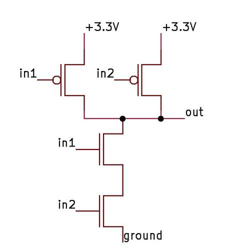
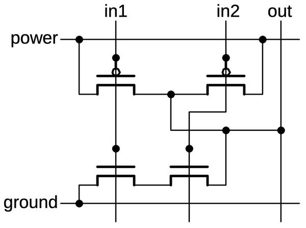
Another common gate in the Pentium is the NAND gate. The schematic below shows a NAND gate with two PMOS transistors above and two NMOS transistors below. If both inputs are high, the two NMOS transistors turn on, pulling the output low. If either input is low, a PMOS transistor turns on, pulling the output high. (Recall that NMOS and PMOS are opposites: a high voltage turns an NMOS transistor on while a low voltage turns a PMOS transistor on.) Thus, the CMOS circuit below produces the desired output for the NAND function.

Schematic of a CMOS NAND gate.

Schematic of a CMOS NAND gate.

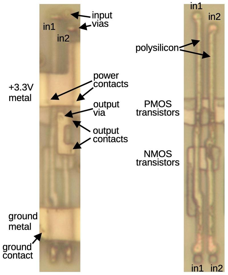
The implementation of the gate as a standard cell, below, follows the schematic. The left photo shows the circuit with one layer of metal (M1). A thick metal line provides 3.3 volts to the gate; it has two contacts that provide power to the two PMOS transistors. The metal line for ground is similar, except only one NMOS transistor is grounded. The thinner metal in the middle has two contacts to get the transistor outputs and a via to connect the output to the M2 metal layer on top. Finally, two tiny bits of M1 metal connect the inputs from the M2 layer to the underlying polysilicon.

Implementation of a CMOS NAND gate as a standard cell.

Implementation of a CMOS NAND gate as a standard cell.

The right photo shows the circuit with all metal removed, showing the polysilicon and silicon. Since a transistor is formed where a polysilicon line crosses doped silicon, the two polysilicon lines create four transistors. Polysilicon functions both as local wiring and as the transistor gates. In particular, the inputs can be connected at the top or bottom of the circuit (or both), depending on what works best for wiring the circuitry. Note that the transistors are squashed together so the silicon in the middle is part of two transistors. An important asymmetry is that the output is taken from the middle of the PMOS transistors, wiring them in parallel, while the output is taken from the right side of the NMOS transistors, wiring them in series.

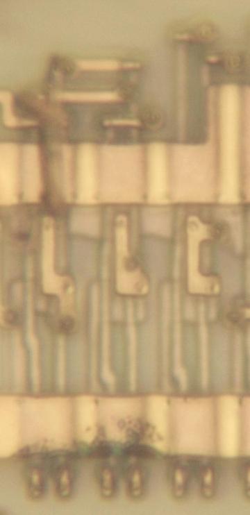
Zooming out a bit, the photo below shows three NAND gates. Although the underlying standard cell is the same for each one, there are differences between the gates. At the top, horizontal wiring links the inputs to M2 through vias. The length of each polysilicon line depends on the position of the metal. Moreover, in the middle of each gate, the metal connection to the output is positioned differently. Finally, note that the power wiring shifts upward in the upper right corner; this is to make room for a larger cell to the right. The point is that the standard cells aren't simply copies of each other, but are adjusted in each case to put the inputs, outputs, and power in the right location. Also note that these standard cells are not isolated, but are squeezed together so the PMOS transistors are touching. This optimization slightly increases the density.

Three NAND gates in the Pentium.

Three NAND gates in the Pentium.

OR-NAND gate

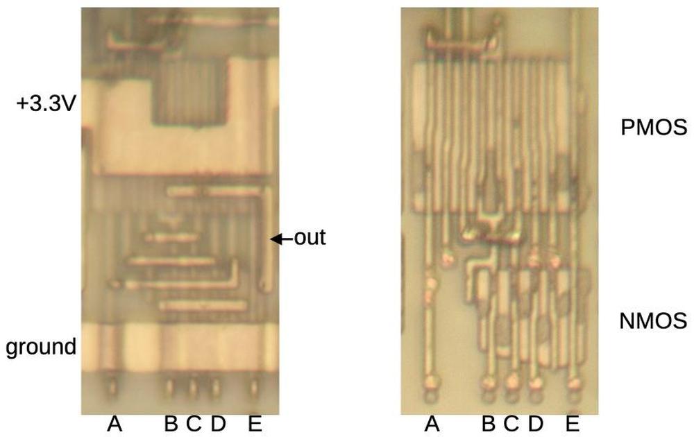
The standard cell library includes some complex gates. For instance, the gate below is a 5-input OR-NAND gate, computing ~((A+B+C+D)⋅E). In the NMOS circuit, transistors A through D are paralleled while E is in series. The PMOS circuit is the opposite, with A through D in series and E in parallel. To provide sufficient current, the PMOS circuit has two sets of transistors for A through D, so the PMOS block is much larger than the NMOS block.

The OR-NAND gate as it appears on the die. The left image shows the M1 metal layer while the right image shows the silicon
and polysilicon.

The OR-NAND gate as it appears on the die. The left image shows the M1 metal layer while the right image shows the silicon and polysilicon.

Latch

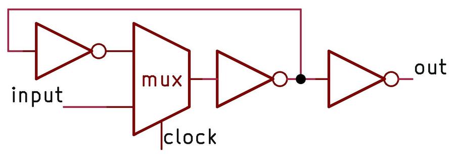
One of the key building blocks of the Pentium's circuitry is the latch. The idea of the latch is to hold one bit, controlled by the clock signal. A latch is "transparent": the latch's input immediately appears on the output while the clock is high. But when the clock is low, the latch holds its previous value. The latch is implemented with a feedback loop that passes the latch's output back into the latch. The heart of this latch circuit is the multiplexer (mux), which selects either the previous output (when the clock is low) or the new input (when the clock is high). The inverters amplify the feedback signal so it doesn't decay in the loop. An inverter also amplifies the output so it can drive other circuitry.

The circuit for a latch.

The circuit for a latch.

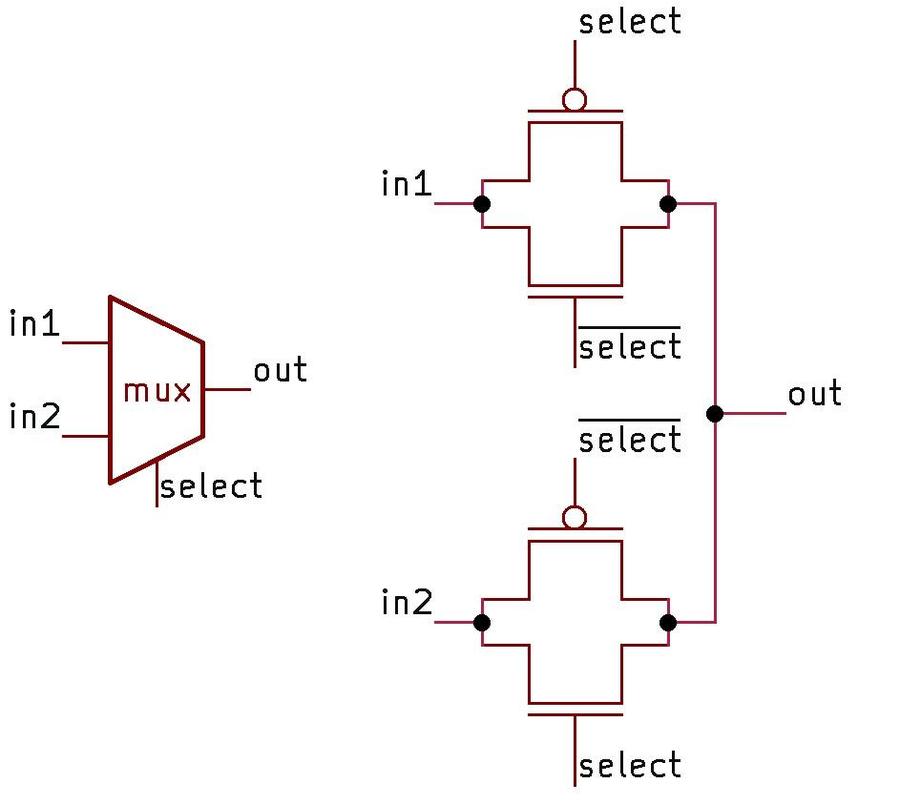
The circuit for a multiplexer is interesting since it uses "pass transistors". That is, the transistors simply pass their input through to the output, rather than pulling a signal to power or ground as in a typical logic gate. The schematic shows how this works. First, suppose that the select line is low. This will turn on the two transistors connected to the first input, allowing its level to flow to the output. Meanwhile, both transistors connected to the second input will be turned off, blocking that signal. But if the select line is high, everything switches. Now, the two transistors connected to the second input turn on, passing its level to the output. Thus, the multiplexer selects the first input if the control signal is low, and the second input if the control signal is high.

A multiplexer and its implementation in CMOS.

A multiplexer and its implementation in CMOS.

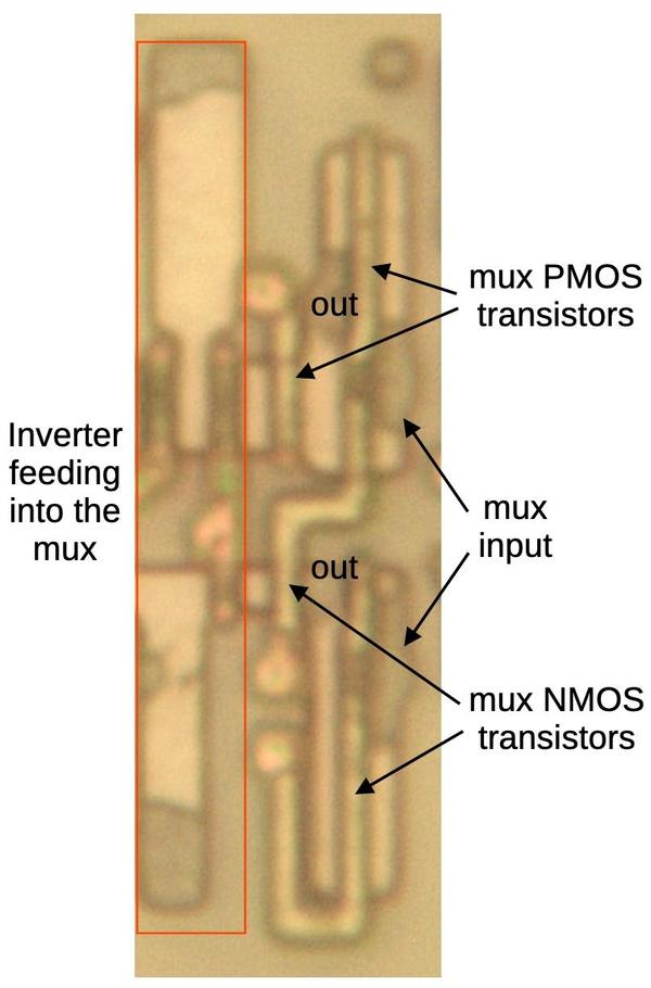
The diagram below shows a multiplexer, part of a latch. On the left, an inverter feeds into one input of the multiplexer.7 On the right is the other input to the multiplexer. The output is taken from the middle, between the pairs of the transistors.

A multiplexer as it appears on the Pentium die.

A multiplexer as it appears on the Pentium die.

Note that the multiplexer's circuit is opposite, in a way, to a logic gate. In a logic gate, you want either the NMOS transistor on or the PMOS transistor on, so the output is pulled low or high respectively. This is accomplished by giving the signals on the transistor gates the same polarity, so the same polysilicon line runs through both transistors. In a multiplexer, however, you want the corresponding PMOS and NMOS transistors to turn on at the same time, so they can pass the signal. This requires the signals on the transistor gates to have opposite polarity. One polysilicon line runs through the right PMOS transistor and the left NMOS transistor. The other polysilicon line runs through the left PMOS transistor and the right NMOS transistor, connected by metal wiring (not shown). The multiplexer includes an inverter to provide the necessary signal, but I cropped it out of the diagram below.

The flip-flop

The Pentium makes extensive use of flip-flops. A flip-flop is similar to a latch, except its clock input is edge-sensitive instead of level-sensitive. That is, the flip-flop "remembers" its input at the moment the clock goes from low to high, and provides that value as its output. This difference may seem unimportant, but it turns out to make the flip-flop more useful in counters, state machines, and other clocked circuits.

In the Pentium, a flip-flop is constructed from two latches: a primary latch and a secondary latch. The primary latch passes its value through while the clock is low and holds its value when the clock is high. The output of the primary latch is fed into the secondary latch, which has the opposite clock behavior. The result is that when the clock switches from low to high, the primary latch stops updating its output at the same time that the secondary starts passing this value through, providing the desired flip-flop behavior.

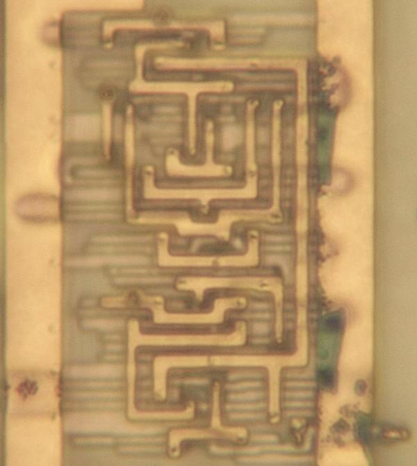
A standard-cell flip-flop.

A standard-cell flip-flop.

The photo above shows a standard-cell flop-flop, with an intricate pattern of metal wiring connecting the various sub-components. There are a few variants; with minor logic changes, the flip-flop can have "set" or "reset" inputs, bypassing the clock to force the output to the desired state. (Set and reset functions are useful for initializing flip-flops to a desired value, for example when the processor starts up.)

The BiCMOS buffer

Although I've been discussing CMOS circuits so far, the Pentium was built with BiCMOS, a process that allows circuits to use bipolar transistors in addition to CMOS. By adding a few extra processing steps to the regular CMOS manufacturing process, bipolar (NPN and PNP) transistors can be created. The Pentium made extensive use of BiCMOS circuits since they reduced signal delays by up to 35%. Intel also used BiCMOS for the Pentium Pro, Pentium II, Pentium III, and Xeon processors (but not the Pentium MMX). However, as chip voltages dropped, the benefit from bipolar transistors dropped too and BiCMOS was eventually abandoned.

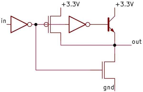
The schematic below shows a standard-cell BiCMOS buffer in the Pentium chip.8 This circuit is more complex than a CMOS buffer: it uses two inverters, an NPN pull-up transistor, an NMOS pull-down transistor, and a PMOS pull-up transistor.9

Reverse-engineered schematic of the BiCMOS buffer.

Reverse-engineered schematic of the BiCMOS buffer.

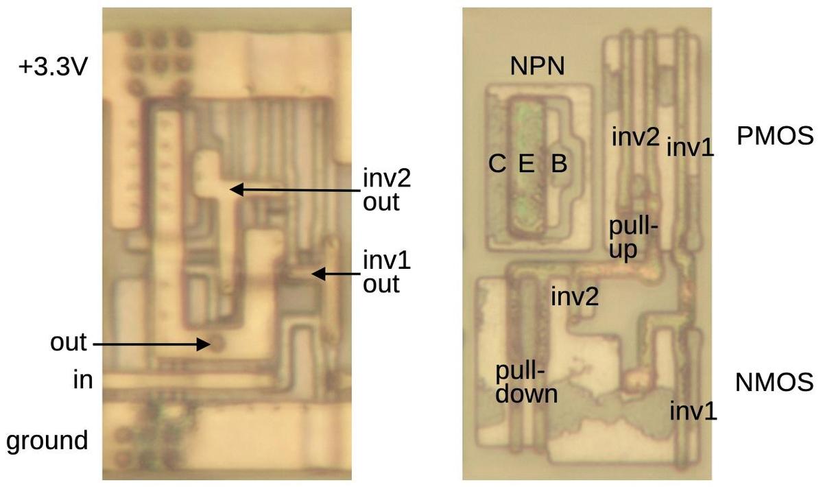
In the die images below, note the circular structure of the NPN transistor, very different from the linear structure of the NMOS and PMOS transistors and considerably larger. A sign of the buffer's high-current drive capacity is the output's thick metal wiring, much thicker than the typical signal wiring.

A BiCMOS buffer in the Pentium.

A BiCMOS buffer in the Pentium.

Conclusions

Standard-cell layout is extensively used in modern chips. Modern processors, with their nanometer-scale transistors, are much too small to study under a microscope. The Pentium, on the other hand, has features large enough that its circuits can be observed and reverse engineered. Of course, with 3.3 million transistors, the Pentium is too much for me to reverse engineer in depth, but I still find it interesting to study small-scale circuits and see how they were implemented. This post presented a small sample of the standard cells in the Pentium. The full standard-cell library is much larger, with dozens, if not hundreds, of different cells: many types of logic gates in a variety of sizes and drive strengths. But the fundamental design and layout principles are the same as the cells described here.

One unusual feature of the Pentium is its use of BiCMOS circuitry, which had a peak of popularity in the 1990s, right around the era of the Pentium. Although changing tradeoffs made BiCMOS impractical for digital circuitry, BiCMOS still has an important role in analog ICs, especially high-frequency applications. The Pentium in a sense is a time capsule with its use of BiCMOS.

I hope that you have enjoyed this look at some of the Pentium's circuits. I find it reassuring to see that even complex processors are made up of simple transistor circuits and you can observe and understand these circuits if you look closely.

For more on standard-cell circuits, I wrote about standard cells in an IBM chip and standard cells in the 386 (the 386 article has a lot of overlap with this one). Follow me on Twitter @kenshirriff or RSS for updates. I'm also on Mastodon occasionally as @[email protected].

Notes and references

  1. In this blog post, I'm focusing on the "P54C" version of the original Pentium processor. Intel produced many different versions of the Pentium, and it can be hard to keep them straight. Part of the problem is that "Pentium" is a brand name, with multiple microarchitectures, lines, and products. At the high level, the Pentium (1993) was followed by the Pentium Pro (1995) Pentium II (1997), Pentium III (1999), Pentium 4 (2000), and so on. The original Pentium used the P5 microarchitecture, a superscalar microarchitecture that was advanced but still executed instruction in order like traditional microprocessors. The Pentium Pro was a major jump, implementing a microarchitecture called P6 that broke instructions into micro-operations and executed them out of order using dataflow techniques. The next microarchitecture version was NetBurst, first used with the Pentium 4. NetBurst provided a deep pipeline and introduced hyper-threading, but it was disappointingly slow and was replaced by the Core microarchitecture. The Core microarchitecture is based on the P6 and is Intel's current microarchitecture.

    I'll focus now on the original Pentium, which went through several substantial revisions. The first Pentium product was the 80501 (codenamed P5), running at 60 or 66 MHz and using 5 volts. These chips were built with an 800 nm process and contained 3.1 million transistors.

    The power consumption of these chips was disappointing, so Intel improved the chip, producing the 80502. These chips, codenamed P54C, used 3.3 volts and ran at 75-120 MHz. The chip's architecture remained essentially the same but support was added for multiprocessing, boosting the transistor count to 3.3 million. The P54C had a much more advanced clock circuit, allowing the external bus speed to stay low (50-66 MHz) while the internal clock speed—and thus performance—climbed to 100 MHz. The chips were built with a smaller 600 nm process with four layers of metal, compared to the previous three. Visually, the die of the P54C is almost the same as the P5, with the additional multiprocessing logic at the bottom and the clock circuitry at the top. For this article, I examined the P54C, but the standard cells should be similar in other versions.

    Next, Intel moved to the 350 nm process, producing a smaller, faster Pentium chip, codenamed the P54CS; the die looks almost identical to the P54C (but smaller), with subtle changes to the bond pads. Another variant was designed for mobile use: the Pentium processor with "Voltage Reduction Technology" reduced power consumption by using a 2.9- or 3.1-volt supply for the core and a 3.3-volt supply to drive the I/O pins. These were built first with the 600 nm process (75-100 MHz) and then the 350 nm process (100-150 MHz).

    The biggest change to the original Pentium was the Pentium MMX, with part number 80503 and codename P55C. This chip extended the x86 instruction set with 57 new instructions for vector processing. It was built on a 350 nm process before moving to 280 nm, and had 4.5 million transistors. More obscure variants of the original Pentium include the P54CQS, P54CS, P54LM, P24T, and Tillamook, but I won't get into them. 

  2. Circuits that had a high degree of regularity, such as the arithmetic/logic unit (ALU) or register storage were typically constructed by manually laying out a block to implement the circuitry for one bit and then repeating the block as needed. Because a circuit was repeated 32 times for the 32-bit processor, the additional effort was worthwhile. 

  3. An alternative layout technique is the gate array, which doesn't provide as much flexibility as a standard cell approach. In a gate array (sometimes called a master slice), the chip had a fixed array of transistors (and often resistors). The chip could be customized for a particular application by designing the metal layer to connect the transistors as needed. The density of the chip was usually poor, but gate arrays were much faster to design, so they were advantageous for applications that didn't need high density or produced a relatively small volume of chips. Moreover, manufacturing was much faster because the silicon wafers could be constructed in advance with the transistor array and warehoused. Putting the metal layer on top for a particular application could then be quick. Similar gate arrays used a fixed arrangement of logic gates or flip-flops, rather than transistors. Gate arrays date back to 1967

  4. The behavior of MOS transistors is complicated, so the description above is simplified, just enough to understand digital circuits. In particular, MOS transistors don't simply switch between "on" and "off" but have states in between. This allows MOS transistors to be used in a wide variety of analog circuits. 

  5. The earliest Pentiums had three layers of metal wiring, but Intel moved to a four-layer process with the P54C die, the version that I'm examining. 

  6. To get this level of magnification with my microscope, I had to use an oil immersion lens. Instead of looking at the chip in air, as with a normal lens, I had to put a drop of special microscope oil on the chip. I carefully lower the lens until it dips into the oil (making sure I don't crash the lens into the chip). The purpose of the oil is that its index of refraction is almost the same as glass, much higher than air. This gives the lens a higher "numerical aperture", allowing the lens to resolve smaller details. 

  7. For completeness, I'll mention that the inverter feeding the multiplexer inverter isn't exactly an inverter. Specifically, the inverter's two transistors are not tied together to produce an output. Instead, the inverter's NMOS transistor provides an input to the multiplexer's NMOS transistor and likewise, the PMOS transistor provides an input to the PMOS transistor. The omission of this connection does not affect the circuit's behavior, but it makes calling the circuit an inverter and a multiplexer a bit of an abstraction. 

  8. Intel called this gate "BiNMOS" rather than "BiCMOS" because it uses a bipolar transistor and an NMOS transistor to drive the output, rather than two bipolar transistors. The Pentium's BiCMOS circuitry is described in a conference paper, showing a second NPN transistor to protect the first one. I don't see the second transistor on the die so the two transistors may be implemented in one silicon structure. Reference: R. F. Krick et al., “A 150 MHz 0.6 µm BiCMOS superscalar microprocessor,” IEEE Journal of Solid-State Circuits, vol. 29, no. 12, Dec. 1994, doi:10.1109/4.340418

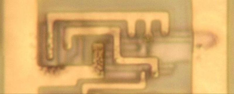
  9. The Pentium contains multiple types of BiCMOS standard cells, which I'll show in this footnote. The cell below is an inverter. It is similar to the BiCMOS buffer described earlier, except it lacks the first inverter in the circuit. To make room for the NPN transistor on the left, the PMOS transistors are shifted to the right. As a result, they don't line up with the PMOS transistors in other cells. This is a break from the traditional orderliness of standard cells.

    A BiCMOS inverter with PMOS on the left and NMOS on the right. The input is at the bottom and the output is in the middle.

    A BiCMOS inverter with PMOS on the left and NMOS on the right. The input is at the bottom and the output is in the middle.

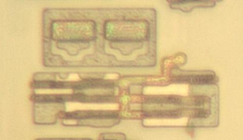
    The BiCMOS inverter below is similar, except it uses two NPN transistors, providing more output drive. I removed the M1 metal layer to provide a better view of the transistors.

    A BiCMOS inverter with two NPN transistors. The PMOS transistors are in the lower left and the NMOS transistors are in the lower right.

    A BiCMOS inverter with two NPN transistors. The PMOS transistors are in the lower left and the NMOS transistors are in the lower right.

    Another interesting BiCMOS circuit is the D flip-flop with enable and BiCMOS output, shown below. This is similar to the earlier flip-flop except it has an enable input, allowing it to either load a new value triggered by the clock, or to hold its earlier value. This allows the flip-flop to remember a value for more than one clock cycle. The additional functionality is implemented by another multiplexer, selecting either the old value or the new value. (This multiplexer is, in a way, one level higher than the multiplexer in each latch.) The transistor for the BiCMOS output is in the upper right, poking out from under the metal. (This circuit might be implemented as two independent cells, one for the flip-flop and one for the driver; I'm not sure.)

    A D flip-flop in the Pentium.

    A D flip-flop in the Pentium.


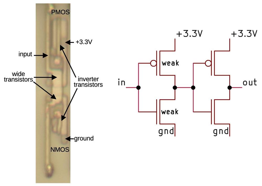
  10. One puzzling inverter variant is used in a gate I'll call the "slow buffer". This buffer consists of two inverters, so it passes its input through to the output, buffered. The strange part is that the first inverter uses transistors with wide gates, which makes these transistors much weaker than regular transistors. As a result, the first inverter will be slow to switch states. My guess is that this circuit is used to delay signals, for example, to keep a signal aligned with another signal that is delayed by multiple logic gates.

    The buffer consists of two inverters. The first inverter uses wide, weak transistors.

    The buffer consists of two inverters. The first inverter uses wide, weak transistors.

    You might expect that larger transistors would be stronger, not weaker. The problem is that these transistors are larger in the wrong dimension. If you make the gate wider, the effect is similar to multiple transistors in parallel, providing more current. But if you make the gate longer (as in this case), the effect is similar to multiple transistors in series, so the resistances add and the total current is reduced. In most cases, transistors are constructed with the smallest gate length possible, which is determined by the manufacturing process, so the transistors here are unusual. This chip was manufactured with an 800 nm process, so the smallest gate length is approximately 800 nm. The gate width (the normal direction for variation) varies dramatically depending on the circuit, optimized to provide maximum performance. 

Reverse engineering standard cell logic in the Intel 386 processor

The 386 processor (1985) was Intel's most complex processor at the time, with 285,000 transistors. Intel had scheduled 50 person-years to design the processor, but it was falling behind schedule. The design team decided to automate chunks of the layout, developing "automatic place and route" software.1 This was a risky decision since if the software couldn't create a dense enough layout, the chip couldn't be manufactured. But in the end, the 386 finished ahead of schedule, an almost unheard-of accomplishment.

In this article, I take a close look at the "standard cells" used in the 386, the logic blocks that were arranged and wired by software. Reverse-engineering these circuits shows how standard cells implement logic gates, latches, and other components with CMOS transistors. Modern integrated circuits still use standard cells, much smaller now, of course, but built from the same principles.

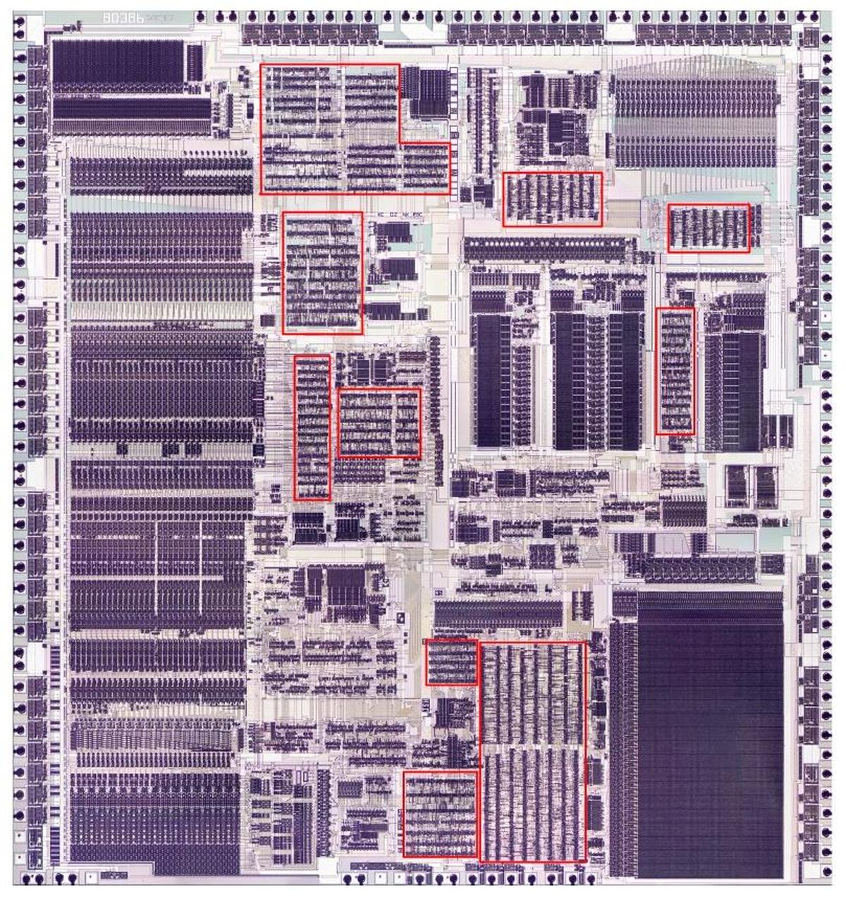
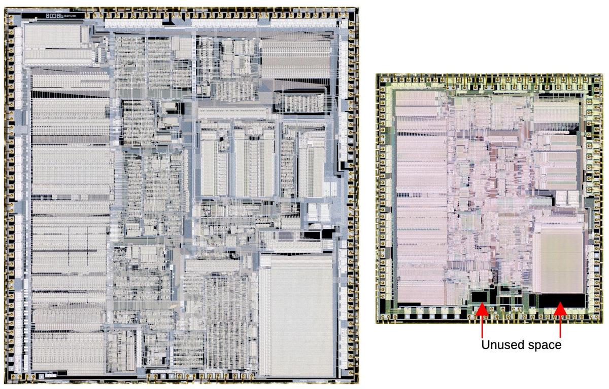
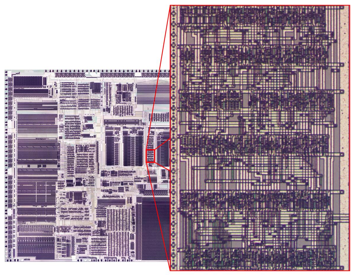
The photo below shows the 386 die with the automatic-place-and-route regions highlighted in red. These blocks of unstructured logic have cells arranged in rows, giving them a characteristic striped appearance. In comparison, functional blocks such as the datapath on the left and the microcode ROM in the lower right were designed manually to optimize density and performance, giving them a more solid appearance. As for other features on the chip, the black circles around the border are bond wire connections that go to the chip's external pins. The chip has two metal layers, a small number by modern standards, but a jump from the single metal layer of earlier processors such as the 286. The metal appears white in larger areas, but purplish where circuitry underneath roughens its surface. For the most part, the underlying silicon and the polysilicon wiring on top are obscured by the metal layers.

Die photo of the 386 processor with standard-cell logic highlighted in red.

Die photo of the 386 processor with standard-cell logic highlighted in red.

Early processors in the 1970s were usually designed by manually laying out every transistor individually, fitting transistors together like puzzle pieces to optimize their layout. While this was tedious, it resulted in a highly dense layout. Federico Faggin, designer of the popular Z80 processor, describes finding that the last few transistors wouldn't fit, so he had to erase three weeks of work and start over. The closeup of the resulting Z80 layout below shows that each transistor has a different, complex shape, optimized to pack the transistors as tightly as possible.2

A closeup of transistors in the Zilog Z80 processor (1976). This chip is NMOS, not CMOS, which provides more layout flexibility. The metal and polysilicon layers have been removed to expose the underlying silicon. The lighter stripes over active silicon indicate where the polysilicon gates were. I think this photo is from the Visual 6502 project but I'm not sure.

A closeup of transistors in the Zilog Z80 processor (1976). This chip is NMOS, not CMOS, which provides more layout flexibility. The metal and polysilicon layers have been removed to expose the underlying silicon. The lighter stripes over active silicon indicate where the polysilicon gates were. I think this photo is from the Visual 6502 project but I'm not sure.

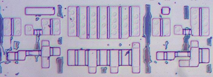
Standard-cell logic is an alternative that is much easier than manual layout.3 The idea is to create a standard library of blocks (cells) to implement each type of gate, flip-flop, and other low-level component. To use a particular circuit, instead of arranging each transistor, you use the standard design. Each cell has a fixed height but the width varies as needed, so the standard cells can be arranged in rows. For example, the die photo below three cells in a row: a latch, a high-current inverter, and a second latch. This region has 24 transistors in total with PMOS above and NMOS below. Compare the orderly arrangement of these transistors with the Z80 transistors above.

Some standard cell circuitry in the 386. I removed the metal and polysilicon to show the underlying silicon. The irregular blotches are oxide that wasn't fully removed, and can be ignored.

Some standard cell circuitry in the 386. I removed the metal and polysilicon to show the underlying silicon. The irregular blotches are oxide that wasn't fully removed, and can be ignored.

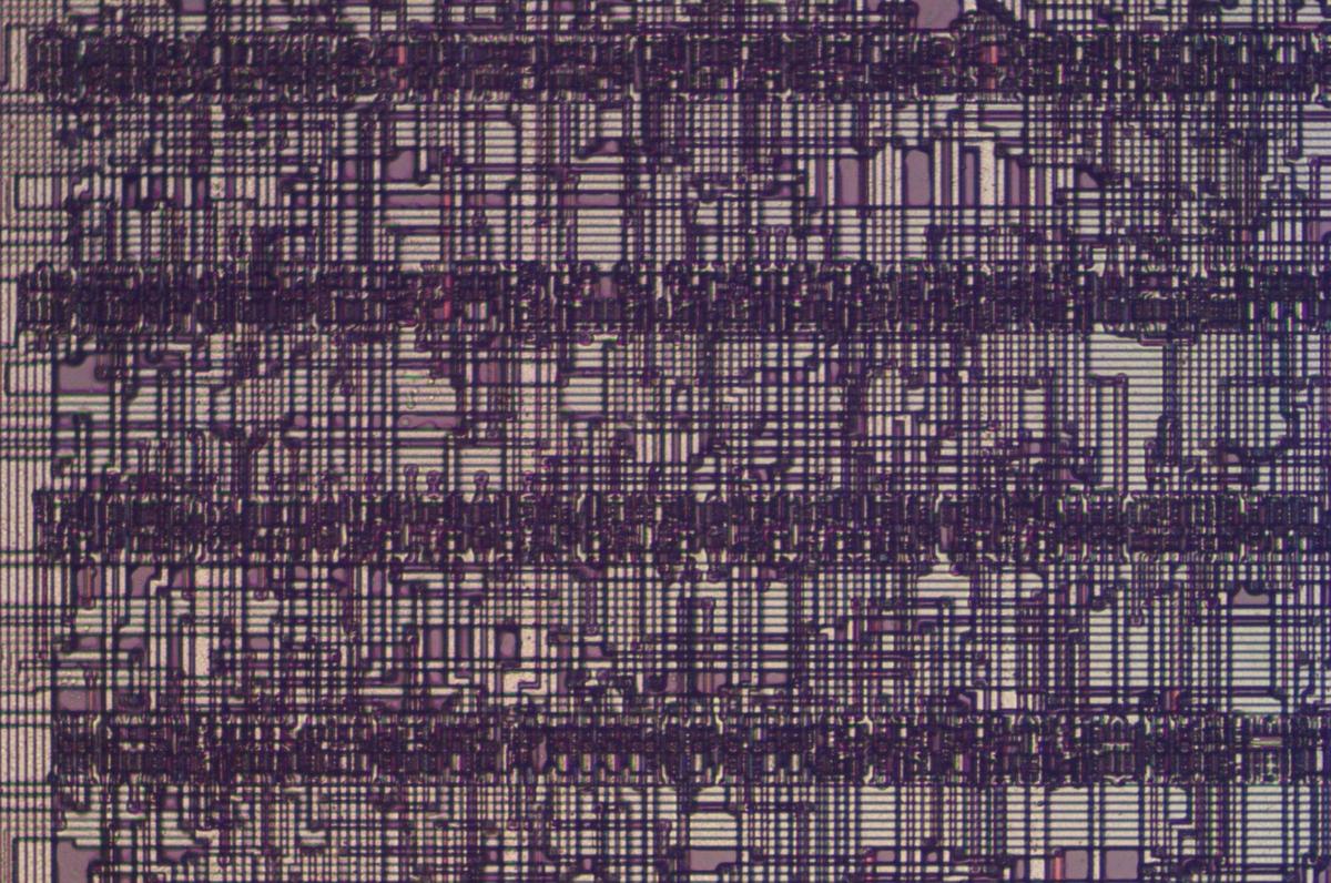
The space between rows is used as a "wiring channel" that holds the wiring between the cells. The photo below zooms out to show four rows of standard cells (the dark bands) and the wiring in between. The 386 uses three layers for this wiring: polysilicon and the upper metal layer (M2) for vertical segments and the lower metal layer (M1) for horizontal segments.

Some standard-cell logic in the 386 processor.

Some standard-cell logic in the 386 processor.

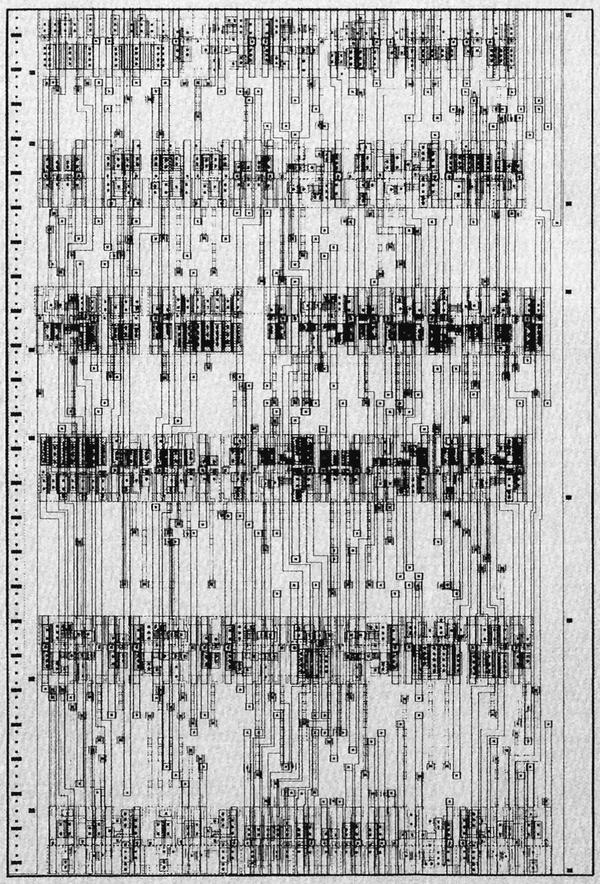
To summarize, with standard cell logic, the cells are obtained from the standard cell library as needed, defining the transistor layout and the wiring inside the cell. However, the locations of each cell (placing) need to be determined, as well as how to arrange the wiring (routing). As will be seen, placing and routing the cells can be done manually or automatically.

Use of standard cells in the 386

Fairly late in the design process, the 386 team decided to use automatic place and route for parts of the chip. By using automatic place and route, 2,254 gates (consisting of over 10,000 devices) were placed and routed in seven weeks. (These numbers are from a paper "Automatic Place and Route Used on the 80386", co-written by Pat Gelsinger, now the CEO of Intel. I refer to this paper multiple times, so I'll call it APR386 for convenience.4) Automatic place and route was not only faster, but it avoided the errors that crept in when layout was performed manually.5

The "place" part of automatic place and route consists of determining the arrangement of the standard cells into rows to minimize the distance between connected cells. Running long wires between cells wastes space on the die, since you end up with a lot of unnecessary metal wiring. But more importantly, long paths have higher resistance, slowing down the signals. Placement is a difficult optimization problem that is NP-complete. Moreover, the task was made more complicated by weighting paths by importance and electrical characteristics, classifying signals as "normal", "fast", or "critical". Paths were also weighted to encourage the use of the thicker M2 metal layer rather than the lower M1 layer.

The 386 team solved the placement problem with a program called Timberwolf, developed by a Berkeley grad student. As one member of the 386 team said, "If management had known that we were using a tool by some grad student as a key part of the methodology, they would never have let us use it." Timberwolf used a simulated annealing algorithm, based on a simulated temperature that decreased over time. The idea is to randomly move cells around, trying to find better positions, but gradually tighten up the moves as the "temperature" drops. At the end, the result is close to optimal. The purpose of the temperature is to avoid getting stuck in a local minimum by allowing "bad" changes at the beginning, but then tightening up the changes as the algorithm progresses.

Once the cells were placed in their positions, the second step was "routing", generating the layout of all the wiring. A suitable commercial router was not available in 1984, so Intel developed its own. As routing is a difficult problem (also NP-complete), they took an iterative heuristic approach, repeatedly routing until they found the smallest channel height that would work. (Thus, the wiring channels are different sizes as needed.) Then they checked the R-C timing of all the signals to find any signals that were too slow. Designers could boost the size of the associated drivers (using the variety of available standard cells) and try the routing again.

Brief CMOS overview

The 386 was the first processor in Intel's x86 line to be built with a technology called CMOS instead of using NMOS. Modern processors are all built from CMOS because CMOS uses much less power than NMOS. CMOS is more complicated to construct, though, because it uses two types of transistors—NMOS and PMOS—so early processors were typically NMOS. But by the mid-1980s, the advantages of switching to CMOS were compelling.

The diagram below shows how an NMOS transistor is constructed. The transistor can be considered a switch between the source and drain, controlled by the gate. The source and drain regions (green) consist of silicon doped with impurities to change its semiconductor properties, forming N+ silicon. The gate consists of a layer of polysilicon (red), separated from the silicon by a very thin insulating oxide layer. Whenever polysilicon crosses active silicon, a transistor is formed. A PMOS transistor has similar construction except it swaps the N-type and P-type silicon, consisting of P+ regions in a substrate of N silicon.

Diagram showing the structure of an NMOS transistor.

Diagram showing the structure of an NMOS transistor.

The NMOS and PMOS transistors are opposite in their construction and operation. An NMOS transistor turns on when the gate is high, while a PMOS transistor turns on when the gate is low. An NMOS transistor is best at pulling its output low, while a PMOS transistor is best at pulling its output high. In a CMOS circuit, the transistors work as a team, pulling the output high or low as needed; this is the "Complementary" in CMOS. (The behavior of MOS transistors is complicated, so this description is simplified, just enough to understand digital circuits.)

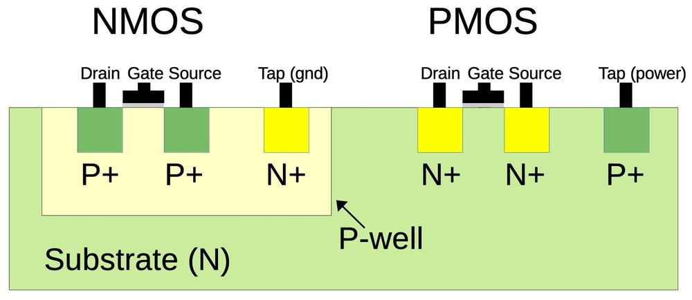
One complication is that NMOS transistors are built on P-type silicon, while PMOS transistors are built on N-type silicon. Since the silicon die itself is N silicon, the NMOS transistors need to be surrounded by a tub or well of P silicon.6 The cross-section diagram below shows how the NMOS transistor on the left is embedded in a well of P-type silicon.

Simplified structure of the CMOS circuits.

Simplified structure of the CMOS circuits.

For proper operation, the silicon that surrounds transistors needs to be connected to the appropriate voltage through "tap" contacts.7 For PMOS transistors, the substrate is connected to power through the taps, while for NMOS transistors the well region is connected to ground through the taps. The chip needs to have enough taps to keep the voltage from fluctuating too much; each standard cell typically has a positive tap and a ground tap.

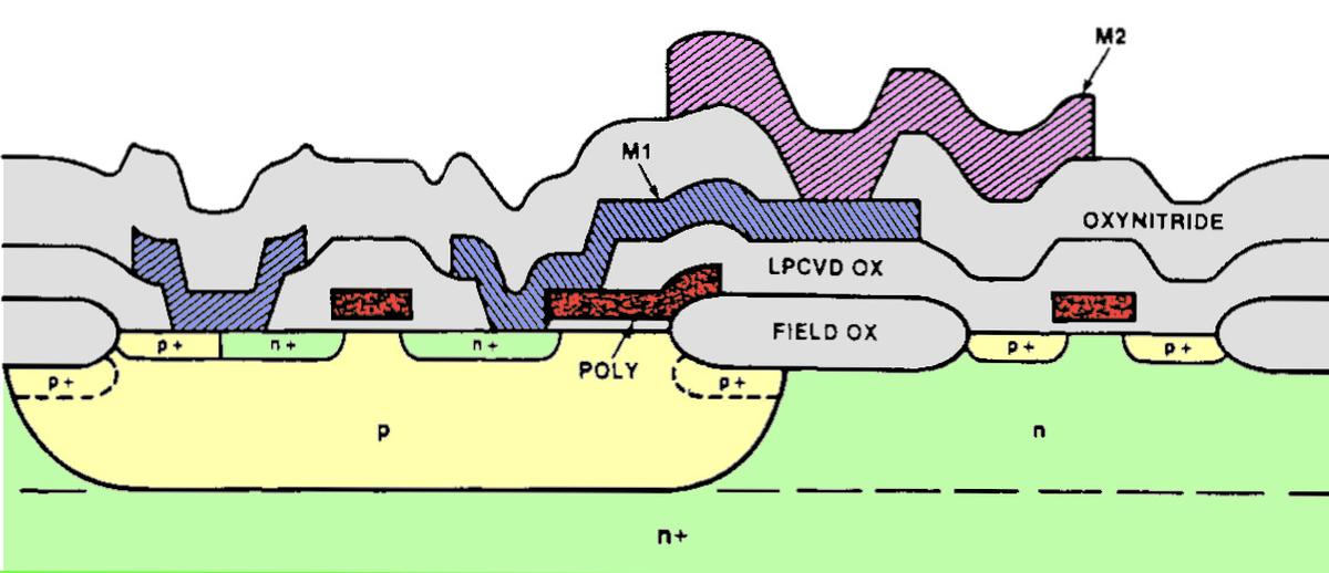
The actual structure of the integrated circuit is much more three-dimensional than the diagram above, due to the thickness of the various layers. The diagram below is a more accurate cross-section. The 386 has two layers of metal: the lower metal layer (M1) in blue and the upper metal layer (M2) in purple. Polysilicon is colored red, while the insulating oxide layers are gray.

Cross-section of CHMOS III transistors. From A double layer metal CHMOS III technology, image colorized by me.

Cross-section of CHMOS III transistors. From A double layer metal CHMOS III technology, image colorized by me.

This complicated three-dimensional structure makes it harder to interpret the microscope images. Moreover, the two metal layers obscure the circuitry underneath. I have removed various layers with acids for die photos, but even so, the images are harder to interpret than those of simpler chips. If the die photos look confusing, don't be surprised.

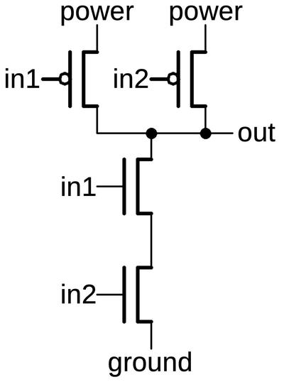
A logic gate in CMOS is constructed from NMOS and PMOS transistors working together. The schematic below shows a NAND gate with two PMOS transistors in parallel above and two NMOS transistors in series below. If both inputs are high, the two NMOS transistors turn on, pulling the output low. If either input is low, a PMOS transistor turns on, pulling the output high. (Recall that NMOS and PMOS are opposites: a high voltage turns an NMOS transistor on while a low voltage turns a PMOS transistor on.) Thus, the CMOS circuit below produces the desired output for the NAND function.

A CMOS NAND gate.

A CMOS NAND gate.

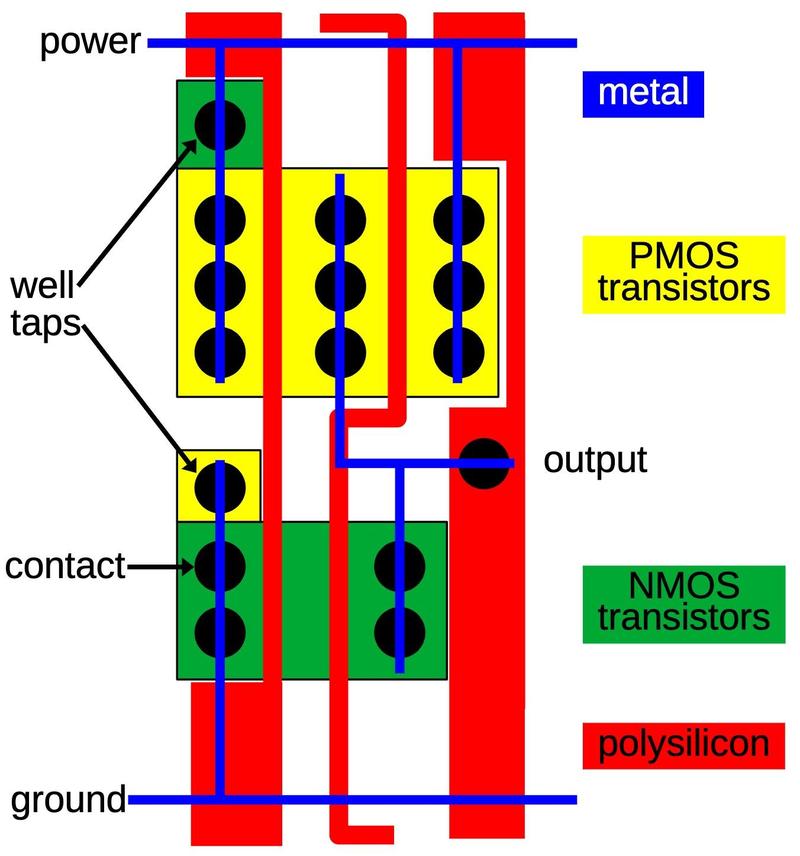
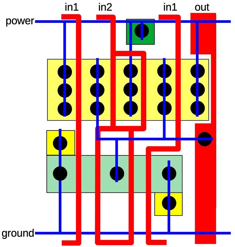
The diagram below shows how this NAND gate is implemented in the 386 as a standard cell.9 A lot is going on in this cell, but it boils down to four transistors, as in the schematic above. The yellow region is the P-type silicon that forms the two PMOS transistors; the transistor gates are where the polysilicon (red) crosses the yellow region.8 (The middle yellow region is the drain for both transistors; there is no discrete boundary between the transistors.) Likewise, the two NMOS transistors are at the bottom, where the polysilicon (red) crosses the active silicon (green). The blue lines indicate the metal wiring for the cell. I thinned these lines to make the diagram clearer; in the actual cell, the metal lines are as thick as they can be without touching, so they cover most of the cell. The black circles are contacts, connections between the metal and the silicon or polysilicon. Finally, the well taps are the opposite type of silicon, connected to the underlying silicon well or substrate to keep it at the proper voltage.

A standard cell for NAND in the 386.

A standard cell for NAND in the 386.

Wiring to a cell's inputs and output takes place at the top or bottom of the cell, with wiring in the channels between rows of cells. The polysilicon input and output lines are thickened at the top and bottom of the cell to allow connections to the cell. The wiring between cells can be done with either polysilicon or metal. Typically the upper metal layer (M2) is used for vertical wiring, while the lower metal layer (M1) is used for horizontal runs. Since each standard cell only uses M1, vertical wiring (M2) can pass over cells. Moreover, a cell's output can also use a vertical metal wire (M2) rather than the polysilicon shown. The point is that there is a lot of flexibility in how the system can route wires between the cells. The power and ground wires (M1) are horizontal so they can run from cell to cell and a whole row can be powered from the ends.

The photo below shows this NAND cell with the metal layers removed by acid, leaving the silicon and the polysilicon. You can match the features in the photo with the diagram above. The polysilicon appears green due to thin-film effects. At the bottom, two polysilicon lines are connected to the inputs.

Die photo of the NAND standard cell with the metal layers removed. The image isn't as clear as I would like, but it was very difficult to remove the metal without destroying the polysilicon.

Die photo of the NAND standard cell with the metal layers removed. The image isn't as clear as I would like, but it was very difficult to remove the metal without destroying the polysilicon.

The photo below shows how the cell appears in the original die. The two metal layers are visible, but they hide the polysilicon and silicon underneath. The vertical metal stripes are the upper (M2) wiring while the lower metal wiring (M1) makes up the standard cell. It is hard to distinguish the two metal layers, which makes interpretation of the images difficult. Note that the metal wiring is wide, almost completely covering the cell, with small gaps between wires. The contacts are visible as dark circles. Is hard to recognize the standard cells from the bare die, as the contact pattern is the only distinguishing feature.

Die photo of the NAND standard cell showing the metal layer.

Die photo of the NAND standard cell showing the metal layer.

One of the interesting features of the 386's standard cell library is that each type of logic gate is available in multiple drive strengths. That is, cells are available with small transistors, large transistors, or multiple transistors in parallel. Because the wiring and the transistor gates have capacitance, a delay occurs when changing state. Bigger transistors produce more current, so they can switch the values on a wire faster. But there are two disadvantages to bigger transistors. First, they take up more space on the die. But more importantly, bigger transistors have bigger gates with more capacitance, so their inputs take longer to switch. (In other words, increasing the transistor size speeds up the output but slows the input, so overall performance could end up worse.) Thus, the sizes of transistors need to be carefully balanced to achieve optimum performance.10 With a variety of sizes in the standard cell library, designers can make the best choices.

The image below shows a small NAND gate. The design is the same as the one described earlier, but the transistors are much smaller. (Note that there is one row of metal contacts instead of two or three.) The transistor gates are about half as wide (measured vertically) so the NAND gate will produce about half the output current.11

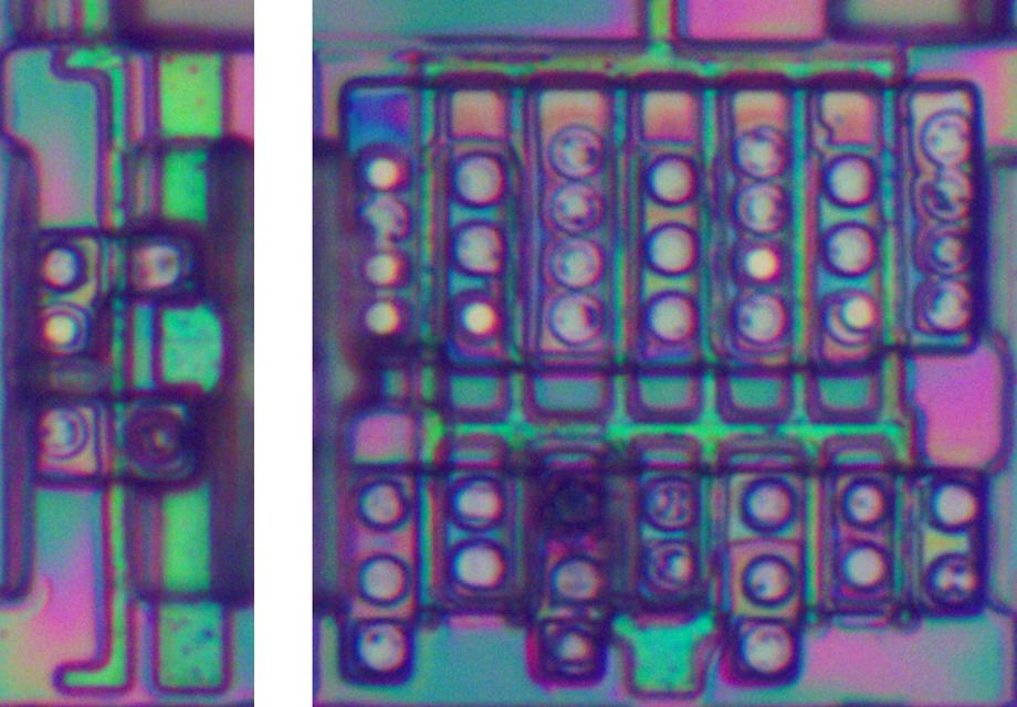
Die photo of a small NAND standard cell with the metal removed.

Die photo of a small NAND standard cell with the metal removed.

Since the standard cells are all the same height, the maximum size of a transistor is limited. To provide a larger drive strength, multiple transistors can be used in parallel. The NAND gate below uses 8 transistors, four PMOS and four NMOS, providing twice as much current.

A large NAND gate as it appears on the die, with the metal removed. The left side is slightly obscured by some remaining oxide.

A large NAND gate as it appears on the die, with the metal removed. The left side is slightly obscured by some remaining oxide.

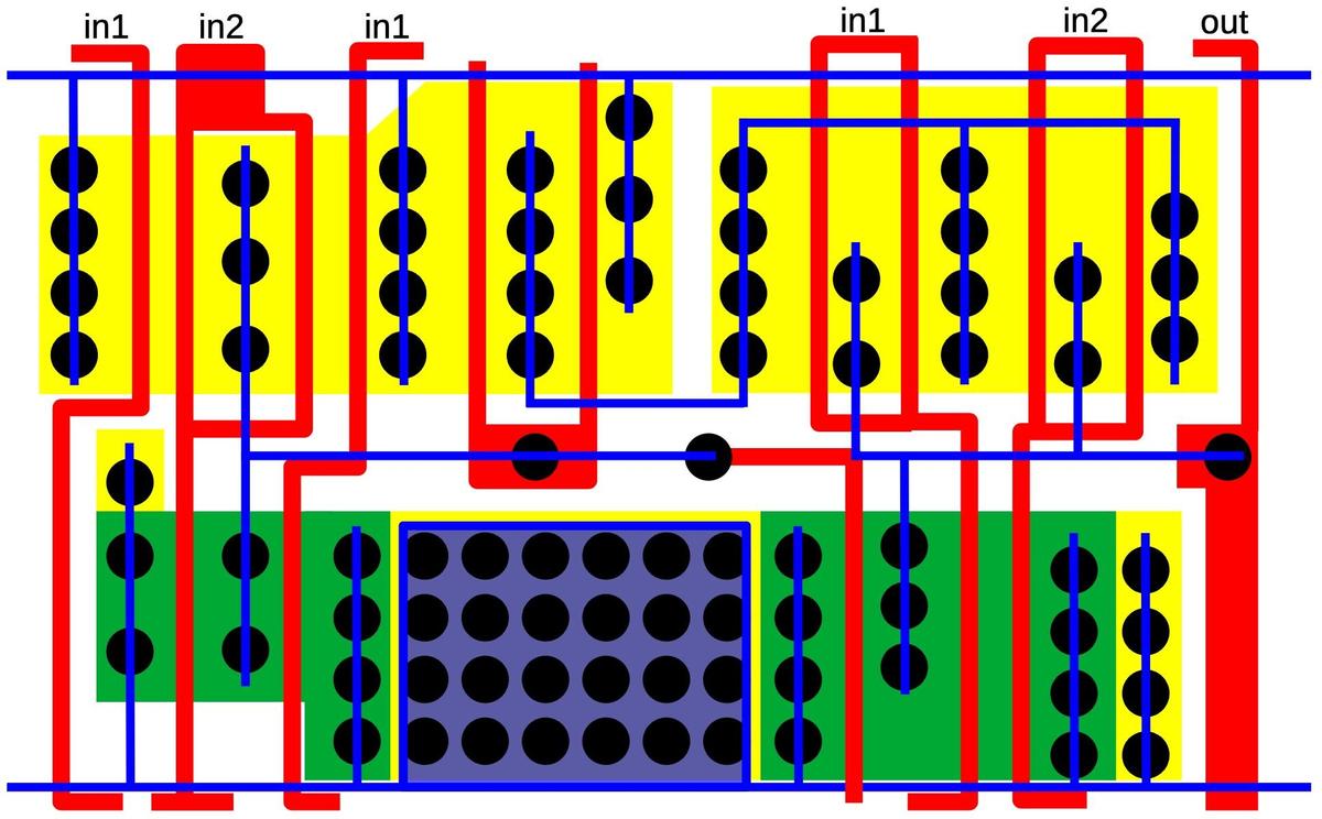
The diagram below shows the structure of the large NAND gate, essentially two NAND gates in parallel. Note that input 1 must be provided separately to both halves by the routing outside the cell. Input 2, on the other hand, only needs to be supplied to the cell once, since it is wired to both halves inside the cell.

A diagram showing the structure of the large NAND gate.

A diagram showing the structure of the large NAND gate.

Inverters are also available in a variety of drive strengths, from very small to very large, as shown below. The inverter on the left uses the smallest transistors, while the inverter on the right not only uses large transistors but is constructed from six inverters in parallel. One polysilicon input controls all the transistors.

A small inverter and a large inverter.

A small inverter and a large inverter.

A more complex standard cell is XOR. The diagram below shows an XOR cell with large drive current. (There are smaller XOR cells). As with the large NAND gate, the PMOS transistors are doubled up for more current. The multiple input connections are handled by the routing outside the cell. Since the NMOS transistors don't need to be doubled up, there is a lot of unused space in the lower part of the cell. The extra space is used for a very large tap contact, consisting of 24 contacts to ground the well.

The structure of an XOR cell with large drive current.

The structure of an XOR cell with large drive current.

XOR is a difficult gate to build with CMOS. The cell above implements it by combining a NOR gate and an AND-NOR gate, as shown below. You can verify that if both inputs are 0 or both inputs are 1, the output is forced low as desired. In the layout above, the NOR gate is on the left, while the AND-NOR gate has the AND part on the right. A metal wire down the center connects the NOR output to the AND-NOR input. The need for two sub-gates is another reason why the XOR cell is so large.

Schematic of the XOR cell.

Schematic of the XOR cell.

I'll describe one more cell, the latch, which holds one bit and is controlled by a clock signal. Latches are heavily used in the 386 whenever a signal needs to be remembered or a circuit needs to be synchronous. The 386 has multiple types of standard cell latches including latches with set or reset controls and latches with different drive strengths. Moreover, two latches can be combined to form an edge-triggered flip-flop standard cell.

The schematic below shows the basic latch circuit, the most common type in the 386. On the right, two inverters form a loop. This loop can stably hold a 0 or 1 value. On the left, a PMOS transistor and an NMOS transistor form a transmission gate. If the clock is high, both transistors will turn on and pass the input through. If the clock is low, both transistors will turn off and block the input. The trick to the latch is that one inverter is weak, producing just a small current. The consequence is that the input can overpower the inverter output, causing the inverter loop to switch to the input value. The result is that when the clock is high, the latch will pass the input value through to the output. But when the clock is low, the latch will hold its previous value. (The output is inverted with respect to the input, which is slightly inconvenient but reduces the size of the latch.)

Schematic of a latch.

Schematic of a latch.

The standard cell layout of the latch (below) is complicated, but it corresponds to the schematic. At the left are the PMOS and NMOS transistors that form the transmission gate. In the center is the weak inverter, with its output to the left. The weak transistors are in the middle; they are overlapped by a thick polysilicon region, creating a long gate that produces a low current.12 At the right is the inverter that drives the output. The layout of this circuit is clever, designed to make the latch as compact as possible. For example, the two inverters share power and ground connections. Notice how the two clock lines pass from top to bottom through gaps in the active silicon so each line only forms one transistor. Finally, the metal line in the center connects the transmission gate outputs and the weak inverter output to the other inverter's input, but asymmetrically at the top so the two inverters don't collide.

The standard cell layout of a latch.

The standard cell layout of a latch.

To summarize, I examined many (but not all) of the standard cells in the 386 and found about 70 different types of cells. These included the typical logic gates with various drive strengths: inverters, buffers, XOR, XNOR, AND-NOR, and 3- and 4-input logic gates. There are also transmission gates including ones that default high or low, as well as multiplexers built from transmission gates. I found a few cells that were surprising such as dual inverters and a combination 3-input and 2-input NAND gate. I suspect these consist of two standard cells that were merged together, since they seem too specialized to be part of a standard cell library.

The APR386 paper showed six of the standard cells in the 386 with the diagram below. The small and large inverters are the same as the ones described above, as is the NAND gate NA2B. The latch is similar to the one described above, but with larger transistors. The APR386 paper also showed a block of standard cells, which I was able to locate in the 386.13

Examples of standard cells, from APR386. The numbers are not defined but may indicate input and output capacitance. (Click for a larger version.)

Examples of standard cells, from APR386. The numbers are not defined but may indicate input and output capacitance. (Click for a larger version.)

Intel's standard cell line

Intel productized its standard cells around 1986 as a 1.5 µm library using Intel's CMOS technology (called CHMOS III).14 Although the library had over 100 cell types, it was very limited compared to the cells used inside the 386. The library included logic gates, flip-flops, and latches as well as scalable registers, counters, and adders. Most gates only came in one drive strength. Even inverters only came in "normal" and "high" drive strength. I assume these cells are the same as the ones used in the 386, but I don't have proof. The library also included larger devices such as a cell-compatible 80C51 microcontroller and PC peripheral chips such as the 8259 programmable interrupt controller and the 8254 programmable interval timer. I think these were re-implemented using standard cells.

Intel later produced a 1.0 µm library using CHMOS IV, for use "both by ASIC customers and Intel's internal chip designers." This library had a larger collection of drive strengths. The 1.0 µm library included the 80C186 and associated peripheral chips.

Layout techniques in the 386

In this section, I'll look at the active silicon regions, making the cells themselves more visible. In the photos below, I dissolved the metal and polysilicon, leaving the active silicon. (Ignore the irregular greenish shapes; these are oxide that wasn't fully removed.)

The photo below shows the silicon for three rows of standard cells using automatic place and route. You can see the wide variety of standard cell widths, but the height of the cells is constant. The transistor gates are visible as the darker vertical stripes across the silicon. You may be able to spot the latch in each row, distinguished by the long, narrow transistors of the weak inverters.

Three rows of standard cells that were automatically placed and routed.

Three rows of standard cells that were automatically placed and routed.

In the first row, the larger PMOS transistors are on top, while the smaller NMOS transistors are below. This pattern alternates from row to row, so the second row has the NMOS transistors on top and the third row has the PMOS transistors on top. The height of the wiring channel between the cells is variable, made as small as possible while fitting the wiring.

The 386 also contains regions of standard cells that were apparently manually placed and routed, as shown in the photo below. Using standard cells avoids the effort of laying out each transistor, so it is still easier than a fully custom layout. These cells are in rows, but the rows are now double rows with channels in between. The density is higher, but routing the wires becomes more challenging.

Three rows of standard cells that were manually placed and routed.

Three rows of standard cells that were manually placed and routed.

For critical circuitry such as the datapath, the layout of each transistor was optimized. The register file, for example, has a very dense layout as shown below. As you can see, the density is much higher than in the previous photos. (The three photos are at the same scale.) Transistors are packed together with very little wasted space. This makes the layout difficult since there is little room for wiring. For this particular circuit, the lower metal layer (M1) runs vertically with signals for each bit while the upper metal layer (M2) runs horizontally for power, ground, and control signals.15

Three rows of standard cells that were manually placed and routed.

Three rows of standard cells that were manually placed and routed.

The point of this is that the 386 uses a variety of different design techniques, from dense manual layout to much faster automated layout. Different techniques were used for different parts of the chip, based on how important it was to optimize. For example, circuits in the datapath were typically repeated 32 times, once for each bit, so manual effort was worthwhile. The most critical functional blocks were the microcode ROM (CROM), large PLAs, ALU, TLB (translation lookaside buffer), and the barrel shifter.16

Conclusions

Standard cell logic and automatic place and route have a long history before the 386, back to the early 1970s, so this isn't an Intel invention.17 Nonetheless, the 386 team deserves the credit for deciding to use this technology at a time when it was a risky decision. They needed to develop custom software for their placing and routing needs, so this wasn't a trivial undertaking. This choice paid off and they completed the 386 ahead of schedule. The 386 ended up being a huge success for Intel, moving the x86 architecture to 32-bits and defining the dominant computer architecture for the rest of the 20th century.

If you're interested in standard cell logic, I wrote about standard cell logic in an IBM chip. I plan to write more about the 386, so follow me on Twitter @kenshirriff or RSS for updates. I'm also on Mastodon occasionally as @[email protected]. Thanks to Pat Gelsinger and Roxanne Koester for providing helpful papers.

Notes and references

  1. The decision to use automatic place and route is described on page 13 of the Intel 386 Microprocessor Design and Development Oral History Panel, a very interesting document on the 386 with discussion from some of the people involved in its development. 

  2. Circuits that had a high degree of regularity, such as the arithmetic/logic unit (ALU) or register storage were typically constructed by manually laying out a block to implement a bit and then repeating the block as needed. Because a circuit was repeated 32 times for the 32-bit processor, the additional effort was worthwhile. 

  3. An alternative layout technique is the gate array, which doesn't provide as much flexibility as a standard cell approach. In a gate array (sometimes called a master slice), the chip had a fixed array of transistors (and often resistors). The chip could be customized for a particular application by designing the metal layer to connect the transistors as needed. The density of the chip was usually poor, but gate arrays were much faster to design, so they were advantageous for applications that didn't need high density or produced a relatively small volume of chips. Moreover, manufacturing was much faster because the silicon wafers could be constructed in advance with the transistor array and warehoused. Putting the metal layer on top for a particular application could then be quick. Similar gate arrays used a fixed arrangement of logic gates or flip-flops, rather than transistors. Gate arrays date back to 1967

  4. The full citation for the APR386 paper is "Automatic Place and Route Used on the 80386" by Joseph Krauskopf and Pat Gelsinger, Intel Technology Journal, Spring 1986. I was unable to find it online. 

  5. Once the automatic place and route process had finished, the mask designers performed some cleanup along with compaction to squeeze out wasted space, but this was a relatively minor amount of work.

    While manual optimization has benefits, it can also be overdone. When the manufacturing process improved, the 80386 moved from a 1.5 µm process to a 1 µm process. The layout engineers took advantage of this switch to optimize the standard cell circuitry, manually squeezing out some extra space. Unfortunately, optimizing one block of a die doesn't necessarily make the die smaller, since the size is constrained by the largest blocks. The result is that the optimized 80386 has blocks of empty space at the bottom (visible as black rectangles) and the standard-cell optimization didn't provide any overall benefit. (As the Pentium Pro chief architect Robert Colwell explains, "Removing the state of Kansas does not make the perimeter of the United States any smaller.")

    Comparison of the 1.5 µm die and the 1 µm die at the same scale. Photos courtesy of Antoine Bercovici.

    Comparison of the 1.5 µm die and the 1 µm die at the same scale. Photos courtesy of Antoine Bercovici.

    At least compaction went better for the 386 than for the Pentium. Intel performed a compaction on the Pentium shortly before release, attempting to reduce the die size. The engineers shrunk the floating point divider, removing some lookup table cases that they proved were unnecessary. Unfortunately, the proof was wrong, resulting in floating point errors in a few cases. This caused the infamous Pentium FDIV bug, a problem that became highly visible to the general public. Replacing the flawed processors cost Intel 475 million dollars. And it turned out that shrinking the floating point divider had no effect on the overall die size.

    Coincidentally, early models of the 386 had an integer multiplication bug, but Intel fixed this with little cost or criticism. The 386 bug was an analog issue that only showed up unpredictably with a combination of argument values, temperature, and manufacturing conditions. 

  6. This chip is built on a substrate of N-type silicon, with wells of P-type silicon for the NMOS transistors. Chips can be built the other way around, starting with P-type silicon and putting wells of N-type silicon for the PMOS transistors. Another approach is the "twin-well" CMOS process, constructing wells for both NMOS and PMOS transistors. 

  7. The bulk silicon voltage makes the boundary between a transistor and the bulk silicon act as a reverse-biased diode, so current can't flow across the boundary. Specifically, for a PMOS transistor, the N-silicon substrate is connected to the positive supply. For an NMOS transistor, the P-silicon well is connected to ground. A P-N junction acts as a diode, with current flowing from P to N. But the substrate voltages put P at ground and N at +5, blocking any current flow. The result is that the bulk silicon can be considered an insulator, with current restricted to the N+ and P+ doped regions. If this back bias gets reversed, for example, due to power supply fluctuations, current can flow through the substrate. This can result in "latch-up", a situation where the N and P regions act as parasitic NPN and PNP transistors that latch into the "on" state. This shorts power and ground and can destroy the chip. The point is that the substrate voltages are very important for the proper operation of the chip. 

  8. I'm using the standard CMOS coloring scheme for my diagrams. I'm told that Intel uses a different color scheme internally. 

  9. The schematic below shows the physical arrangement of the transistors for the NAND gate, in case it is unclear how to get from the layout to the logic gate circuit. The power and ground lines are horizontal so power can pass from cell to cell when the cells are connected in rows. The gate's inputs and outputs are at the top and bottom of the cell, where they can be connected through the wiring channels. Even though the transistors are arranged horizontally, the PMOS transistors (top) are in parallel, while the NMOS transistors (bottom) are in series.

    Schematic of the NAND gate as it is arranged in the standard cell.

    Schematic of the NAND gate as it is arranged in the standard cell.


  10. The 1999 book Logical Effort describes a methodology for maximizing the performance of CMOS circuits by correctly sizing the transistors. 

  11. Unfortunately, the word "gate" is used for both transistor gates and logic gates, which can be confusing. 

  12. You might expect that these transistors would produce more current since they are larger than the regular transistors. The reason is that a transistor's current output is proportional to the gate width divided by the length. Thus, if you make the transistor bigger in the width direction, the current increases, but if you make the transistor bigger in the length direction, the current decreases. You can think of increasing width as acting as multiple transistors in parallel. Increasing length, on the other hand, makes a longer path for current to get from the source to the drain, weakening it. 

  13. The APR386 paper discusses the standard-cell layout in detail. It includes a plot of a block of standard-cell circuitry (below).

    A block of standard-cell circuitry from APR386.

    A block of standard-cell circuitry from APR386.

    After carefully studying the 386 die, I was able to find the location of this block of circuitry (below). The two regions match exactly; they look a bit different because the M1 metal layer (horizontal) doesn't show up in the plot above.

    The same block of standard cells on the 386 die.

    The same block of standard cells on the 386 die.


  14. Intel's CHMOS III standard cells are documented in Introduction to Intel Cell-Based Design (1988). The CHMOS IV library is discussed in Design Methodology for a 1.0µ Cell-based Library Efficiently Optimized for Speed and Area. The paper Validating an ASIC Standard Cell Library covers both libraries. 

  15. For details on the 386's register file, see my earlier article

  16. Source: "High Performance Technology Circuits and Packaging for the 80386", Jan Prak, Proceedings, ICCD Conference, Oct. 1986. 

  17. I'll provide more history on standard cells in this footnote. RCA patented a bipolar standard cell in 1971, but this was a fixed arrangement of transistors and resistors, more of a gate array than a modern standard cell. Bell Labs researched standard cell layout techniques in the early 1970s, calling them Polycells, including a 1973 paper by Brian Kernighan. By 1979 A Guide to LSI Implementation discussed the standard cell approach and it was described as well-known in this patent application. Even so, Electronics called these design methods "futuristic" in 1980.

    Standard cells became popular in the mid-1980s as faster computers and improved design software made it practical to produce semi-custom designs that used standard cells. Standard cells made it to the cover of Digital Design in August 1985, and the article inside described numerous vendors and products. Companies like Zymos and VLSI Technology (VTI) focused on standard cells. Traditional companies such as Texas Instruments, NCR, GE/RCA, Fairchild, Harris, ITT, and Thomson introduced lines of standard cell products in the mid-1980s.