Fixing the Ethernet board from a vintage Xerox Alto

A Xerox Alto system on the East coast had Ethernet problems, so the owner sent me the Ethernet board to diagnose. (After restoring our Alto, we've heard from a couple other Alto owners and try to help them out.) This blog post describes how I repaired the board and explains a bit about how the Alto's groundbreaking Ethernet worked.

The Alto was a revolutionary computer designed at Xerox PARC in 1973, introducing the GUI, high-resolution bitmapped displays and laser printers to the world. But one of its most important contributions was Ethernet, the local area network that is still heavily used today. While modern Ethernets handle up to 100 gigabits per second, the Alto's Ethernet was much slower, just 3 megabits per second over coaxial cable. Even so, the Alto used the Ethernet for file servers, email, network boot, distributed games and even voice over Ethernet.

An extender board made it easy to probe the Ethernet card in the Xerox Alto. The chassis is pulled out to access the boards.  Above the chassis is the disk drive, which stores just 2.5 megabytes on a 14-inch disk pack.

An extender board made it easy to probe the Ethernet card in the Xerox Alto. The chassis is pulled out to access the boards. Above the chassis is the disk drive, which stores just 2.5 megabytes on a 14-inch disk pack.

The Alto's chassis slides out of the cabinet, allowing access to the circuit boards (see above). To test the Ethernet board, I plugged it into the Alto we've restored. The Ethernet board is hanging out the right side of the chassis because I used an extender board.

The board had a couple straightforward problems—a chip with a bent pin (which I straightened) and another chip with broken pins. (While some people recommend re-seating chips on old boards, this can create new problems.) The broken chip was a 74S86, a quadruple XOR gate that has been obsolete for years (if not decades). I replaced it with a 74LS86, a similar but non-obsolete chip.1

When I powered up the Alto, I didn't get anything from the Ethernet board: it was not sending or receiving successfully. This double failure was a bit surprising since malfunctions usually affect just one direction. But I quickly discovered a trivial problem: when I pulled out the Alto's cabinet to access the circuit boards, the Ethernet connector on the back came loose. After plugging the connector in, I saw that the Alto was sending packets successfully, but still wasn't receiving anything.

Oscilloscope trace from the Ethernet board. Yellow is input data, green is R-C filtered, blue is detected edges. The blue trace is a bit of a mess with runt pulses.

Oscilloscope trace from the Ethernet board. Yellow is input data, green is R-C filtered, blue is detected edges. The blue trace is a bit of a mess with runt pulses.

I started probing the Ethernet board's input circuit with the oscilloscope. The board was receiving the input okay, but a few gates later the signals looked kind of sketchy, as you can see above. The yellow trace is the input Ethernet signal. The board applies an R-C filter (green) and then the signal edges are detected (blue). While the input (yellow) is a clean signal, the green signals only go up to about 2 volts, not the expected 4-5 volts. Even worse, the blue waveform is irregular and has "runt" pulses—short irregular signals that don't go all the way up. With waveforms like this, the board wouldn't be able to process the input.

Manchester encoding and the decoding circuit

I'll take a detour to explain the Ethernet's Manchester encoding, before getting into the details of the circuitry.

The Alto's Ethernet encoded data over the coaxial cable using Manchester encoding.32 In this encoding, a 1 bit is sent as a 1 followed by a 0, while a 0 bit is sent as a 0 followed by a 1. The diagram below shows how the bits "0110" would be encoded. A key reason to use this encoding is that simplifies timing on the receiver, since it is self-clocking. Note that there is a transition in the middle of each cell that can be used as a clock. (The obvious scheme of just sending the bits directly has the problem that in a long string of 0's, it's hard to know exactly how many were transmitted.)

An example of Manchester encoding, for the bits 0110.

An example of Manchester encoding, for the bits 0110.

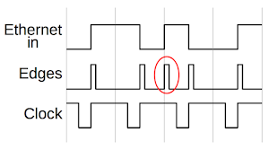
To decode the Ethernet signal arriving at the Alto, the first step is to extract the clock signal that indicates the timing of the bits. To extract the clock, the transitions in the middle of each bit cell must be detected. The trick is to ignore transitions at the edges of cells. The diagram below shows how the clock is extracted. First, edge pulses are generated for each transition edge of the input. Then, a clock pulse is generated for each edge pulse. The clock pulse about 75% of the width of the bit cell, and any second pulse that happens while the clock is still high is blocked. (The edge circled in red is an example of an ignored edge.) The result is the steady clock signal, synchronized to the input.4 This clock is used to latch the input signal value into a shift register, which converts the serial Ethernet stream into a word value usable by the Alto.

Extracting the clock signal from a Manchester-encoded Ethernet input. Edges are extracted from the input signal and used to trigger the clock. An edge too close to the previous (red) is dropped.

Extracting the clock signal from a Manchester-encoded Ethernet input. Edges are extracted from the input signal and used to trigger the clock. An edge too close to the previous (red) is dropped.

The schematic5 below shows the circuit that performs this clock extraction. There are a few tricks in this interesting semi-analog circuit. When the Ethernet input signal changes, the low-pass R-C (resistor capacitor) filter output will be slower to change. This will cause the edge detect XOR gate to go high briefly until the R-C signal catches up. Then the clock is generated by a "one-shot", a chip that generates a fixed-width pulse for each input pulse. The pulse width is set to about 75% of the bit cell width by another resistor and capacitor. The one-shot is wired to ignore any additional pulses that occur while the clock output is high.

Schematic of the clock extraction circuit in the Xerox Alto's Ethernet interface.

Schematic of the clock extraction circuit in the Xerox Alto's Ethernet interface.

Since the timing in this circuit was controlled by multiple resistors and capacitors, I thought that a capacitor might have gone out of tolerance. But first I decided to do the simpler test of swapping the XOR chip with the one from our working Alto board. Surprisingly, this fixed the problem, and the Ethernet board now functioned flawlessly. Thus, while the 74LS86 has input characteristics similar to the 74S86, they weren't close enough, and substituting the more modern chip messed up the R-C filter's behavior. (If the gate draws too much input current, the capacitor won't charge as fast.) Marc dug through his collection of old chips and found another 74S86 so we could get both boards operating.

Oscilloscope trace showing the extracted clock (pink), edges of the Ethernet input (yellow) and the R-C filtered input (green).

Oscilloscope trace showing the extracted clock (pink), edges of the Ethernet input (yellow) and the R-C filtered input (green).

The oscilloscope trace above shows the nice, steady clock (pink) after replacing the XOR chip. With the right XOR chip, the RC-filtered signal (green) rises to 4 volts, unlike before when it just went to 2 volts. The edge signal (yellow) is nice and even, without the "runt pulses" seen earlier.

An overview of the Ethernet board

I'll wrap up by explaining a bit about the Alto's Ethernet board (shown in the photo below). The large connector at the left plugs into the Alto's backplane, providing communication with the rest of the system. The small connector at the right connects to the Ethernet, via a transceiver. Some of the key components of the Ethernet interface are labeled on the diagram below. With this generation of chips, even a whole board of chips doesn't give you a lot of functionality so much of the Ethernet functionality is implemented in software and microcode.

The Xerox Alto's Ethernet board, showing major functional blocks.

The Xerox Alto's Ethernet board, showing major functional blocks.

Most of the chips are simple TTL logic, but the board uses a few interesting and obscure chips. Input and output data goes through a 16-word FIFO buffer built from four Intel 3101A RAM chips; each one holds just 16×4 bits. (The 3101 was Intel's first product.) Commands to the Ethernet board are decoded by three Intel 3205 decoder chips. Buffer chips interface between the card and the Alto's bus. Shift registers for the input and output convert between data words and serial data over the Ethernet. The CRC error checking is done by a specialized Fairchild 9401 CRC chip. Surprisingly, the Manchester encoding is implemented with a PROM-driven state machine, built from two Intel 3601 PROMs. Finally, the XOR chip is the chip that caused all the problems.5

The board has TTL inputs and outputs, so it doesn't connect directly to the Ethernet cable. Instead, a transceiver box is the interface between the Alto and the cable. In the photo below, you can see the transceiver clamped onto the coaxial cable. The transceiver converts the Alto's logic signals to the signals on the cable and injects the signals through an isolation transformer. In addition, the transceiver detects collisions if the Alto tries to send at the same time as another machine on the network.

The transceiver injects the Xerox Alto's signals into the Ethernet coaxial cable and reads signals from the cable.

The transceiver injects the Xerox Alto's signals into the Ethernet coaxial cable and reads signals from the cable.

You might wonder how the Alto can communicate with a modern system, since the Alto's 3 Mb/s Ethernet isn't compatible with modern Ethernet. I am building a gateway based on the BeagleBone (below) that uses the BeagleBone's microcontroller (the PRU) to "bit bang" the Ethernet signals. The BeagleBone also runs an implementation of IFS (Interim File System), the server side software to support the Alto. This is a C# implementation of IFS written by the Living Computers Museum.

I'm building an interface to the Alto's 3Mb/s Ethernet, using a BeagleBone. The cable on the right goes to the Alto's Ethernet port, while a standard Ethernet plugs into the left.

I'm building an interface to the Alto's 3Mb/s Ethernet, using a BeagleBone. The cable on the right goes to the Alto's Ethernet port, while a standard Ethernet plugs into the left.

Conclusion

Bob Metcalfe invented Ethernet at Xerox PARC between 1973 and 1974, with a 3 megabit per second Ethernet for the Alto. Since then, Ethernet has become a ubiquitous standard, and has increased in speed more than 4 orders of magnitude. Unfortunately, as with many other technologies, Xerox failed to take advantage of Ethernet as a product. Instead, Bob Metcalfe left Xerox in 1979 and formed the company 3Com, which sold Ethernet products and became one of the most successful technology firms of the 1990s.

I tracked down a problem in an Alto Ethernet board—my replacement for a broken chip was almost the same, but incompatible enough to make the circuit fail. The problem showed up in the circuit that extracted the clock from the incoming Ethernet signal. This circuit illustrates some clever techniques used by the Alto designers to implement Ethernet with simple TTL chips.

The Ethernet card plugged into the Xerox Alto's chassis. The disk drive is above the chassis, with a white 14" disk pack visible inside.

The Ethernet card plugged into the Xerox Alto's chassis. The disk drive is above the chassis, with a white 14" disk pack visible inside.

The Alto I've been restoring came from YCombinator; the restoration team includes Marc Verdiell, Carl Claunch and Luca Severini. My full set of Alto posts is here and Marc's extensive videos of the restoration are here. Thanks to the Living Computers Museum+Labs for the extender card and the IFS software.

You can follow me on Twitter here for updates on the restoration.

Notes and references

  1. The 7400 family of TTL chips has many subfamilies with different characteristics. The 74S components use Schottky diodes for faster performance than standard TTL. The 74LS (low-power Schottky) chips use much less power (1/8 in this case), but are slightly slower and draw slightly different input currents. 

  2. Ethernet started with Manchester encoding and continued to use this encoding up to 10 Mb/s speed. However, Manchester encoding is somewhat inefficient since each bit can have two transitions, doubling the bandwidth requirement. 100 Mb/s Ethernet solved this by using MLT-3 encoding, which uses three voltage levels. To avoid the problem of losing the clock on a long string of 0's, each group of 4 bits is sent as a particular 5 bit pattern that eliminates long repetitive sequences. Ethernet gets progressively more complex as speed increases. At 100 Gb/s Ethernet, blocks of 64 bits are encoded with 66 bit patterns and data is split across multiple lanes. 

  3. Manchester encoding was developed for magnetic drum storage for the University of Manchester's Mark 1 computer. The Mark 1 was an influential early computer from 1949, one of the earliest stored-program computers, also introducing index registers and Williams tube storage. 

  4. One potential problem with the clock extraction is if you have a steady stream of bits (1111... or 0000...) the Ethernet signal will be a steady stream of transitions, and you can't tell where to start the clock. The solution is that each Ethernet transmission starts with a sync bit to get the clock started properly. 

  5. The schematics for the Alto's Ethernet board are at Bitsavers. The Ethernet is described in more detail in the Alto Hardware Manual

Identifying the "Early IBM Computer" in a Twitter photo: a 405 Accounting Machine

The photo below of a "woman wiring an early IBM computer" has appeared on Twitter a bunch of times, and it stoked my curiosity: what was the machine in the photo? Was it really an early IBM computer? I was a bit skeptical since the machine in the photo is much smaller than IBM's first room-filling computers, and there aren't any vacuum tubes visible. I investigated this machine and it turned out to be not a computer, but an IBM 405 "Alphabetic Accounting Machine" from 1934, back in the almost forgotten pre-computer age of tabulating machines.1

A common photo on Twitter shows a woman wiring an early IBM computer.

A common photo on Twitter shows a woman wiring an early IBM computer.

The image is from photographer Berenice Abbott who took many scientific photographs from 1939 to 1958. She photographed everything from basic magnetic field and optics experiments to research on early television tubes, and many of these photos were used in physics textbooks. Her photos (including IBM photos) were published in the book Documenting Science. I had hoped that the book would identify the computer in the photo, but it merely said "IBM Laboratory: Wiring an early IBM computer". Surprisingly for an art book, it didn't even give a date for the photo.

The diagram below shows the back view of an IBM 403 accounting machine, which IBM introduced in 1948.2 (An accounting machine (also called a tabulator) summed up and printed records from punched cards for applications such as payroll or inventory.) Note the similarities with the Abbott photo: the thick laced wire bundles, the vertical wire bundles in the middle for the counters, and the hinged doors that swing open.

Back view of an IBM 403 accounting machine. From the IBM 402/403 Field Engineering Manual.

Back view of an IBM 403 accounting machine. From the IBM 402/403 Field Engineering Manual.

A second Berenice Abbott photo shows the machine from a slightly different angle.3 The "Card Feed Circuit Breaker Unit" in the upper right looks like a perfect match between the IBM 403 and the Abbott photo. The dangling cables from the counters in the middle look right, as well as the thick cable between the counters and the circuit breaker unit. The 403 diagram above shows a large printing carriage on top, while the Abbott photo just shows a base, presumably because the carriage hadn't been installed yet.

A second photo of "Woman wiring an early IBM computer" by Berenice Abbott.

A second photo of "Woman wiring an early IBM computer" by Berenice Abbott.

Although the machine in the Abbott photo looks very similar to the IBM 403, there are a few differences if you look carefully. One clear difference is the IBM 403 had caster wheels attached directly to the frame, while the machine in the photos has stubby curved legs. In addition, the doors of the IBM 403 were hinged at a different place. In the Abbott photos, the doors are attached just to the left of the counters and to the right of the card feed circuit breaker unit. But the IBM 403 has some bulky components to the left of the counters such as the "Bijur pump" (an oil pump), and components on the right such as the drive motor. Overall, the machine in the Abbott photos has a narrower cabinet than the IBM 403. Additionally, the thick cable snaking down between the IBM 403's circuit breaker units appears to go straight down in the photos. Thus, although the machine in the photos is very similar to the IBM 403, it's not an exact match.

After more research into IBM's various accounting machines, I conclude that machine in the photos is the IBM 405, an IBM accounting machine introduced in 1934 (earlier than that 1948 IBM 403 despite the larger model number).4 The IBM 405 (below) had curved legs that match the Abbott photos. In addition, the 405 has a narrower main cabinet than the 403, with bulky additional components attached to the left and right, outside the legs. This matches the narrower cabinet in the Abbott photos. (The 403 was an improved and modernized 405, explaining the overall similarity between the two machines.)

An IBM 405 accounting machine. Photo courtesy of Columbia University Computing History.

An IBM 405 accounting machine. Photo courtesy of Columbia University Computing History.

Punched cards were a key part of data processing from 1890 until the 1970s, used for accounting, inventory, payroll and many other tasks. Typically, each 80-column punched card held one record, with data stored in fixed fields on the card. The diagram below shows a typical card with columns divided into fields such as date, vendor number, order number and amount. An accounting machine would process these cards: totaling the amounts, and generating a report with subtotals by account and department, as shown below.

Example of a punched card holding a 'unit record', and a report generated from these cards. The accounting machine can group records based on a field to produce subtotals, intermediate totals, and totals. From Manual of Operation.

Example of a punched card holding a 'unit record', and a report generated from these cards. The accounting machine can group records based on a field to produce subtotals, intermediate totals, and totals. From Manual of Operation.

Punched-card data processing was invented by Herman Hollerith for the 1890 US census, which used a simple tabulating machine to count census data, stored on punched cards. Tabulating machines steadily became more complex, becoming feature-laden "accounting machines" that could generate business reports. Businesses made heavy use of these electromechanical accounting machines and by 1944, IBM had 10,000 tabulating and accounting machines in the field.

Accounting machines were "programmed" with a removable plugboard. By switching the plugboard, an accounting machine could be rapidly reconfigured for different tasks. Each wire corresponded to one character or digit. Wires plugged into the plugboard connected columns on the input card to adders. Each column on the printer had an associated wire controlling what got printed. Other wires had control functions. (I explained the tax preparation plugboard below in detail in this article.)

Plugboard to generate a tax report on an IBM 403 accounting machine. Courtesy of Carl Claunch.

Plugboard to generate a tax report on an IBM 403 accounting machine. Courtesy of Carl Claunch.

The IBM 405 was IBM's first "Alphabetic Accounting Machine," able to print text as well as numbers. It had more complexity than you might expect from the 1930s, able to generate three levels of subtotals, intermediate totals, and grand totals. It could process up to 150 cards per minute; that's remarkably fast for an electromechanical system, reading and summing more than 2 cards per second. The 405 was IBM's flagship product for many years, with IBM manufacturing 1500 of them per year. Like most IBM machines, the 405 was usually rented rather than purchased; it cost over $1000 a month (equivalent to about $15,000 per month in 2017 dollars). Renting out these machines (and selling the punch cards) was highly profitable for IBM, with the IBM 405 accounting machine called "the most lucrative of all IBM's mechanical glories".5

Amazingly, although accounting machines were designed for business purposes, they were also used for scientific computation in the 1930s and 1940s, before digital computers existed. They solved everything from differential equations and astronomy computations to nuclear bomb simulations for the Manhattan Project.6

How does an accounting machine work and what are all those parts?

Accounting machines (also called tabulators) were built from electromechanical components, rather than transistors or even vacuum tubes. The main components in accounting machines were electromechanical counters and relays. Everything was synchronized to rotating driveshafts that ran the counters, card reader and printer. In a way, accounting machines were more like cars than computers, with a motor, clutches, driveshafts, an oil pump, gears and cams.

Counters

The heart of the accounting machine was the mechanical counter, a digit wheel somewhat like an odometer. Each wheel stored one digit, with the value indicated by the rotational position of the wheel. To add a number, say 3, to the counter, a clutch was briefly activated, causing the drifeshaft to rotate the counter three more positions. Since these counters were adding 2 1/2 numbers per second, they were spinning rapidly with the clutches engaging and disengaging with precision timing. By combining multiple counters, numbers of up to 8 digits could be handled. The counter kept a running total of the numbers fed into it. Since it accumulated these numbers, the counter was known as an accumulator, a term still used in computing.

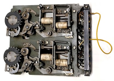
A counter unit from an IBM accounting machine. The two wheels held two digits. The electromagnets (white) engaged and disengaged the clutch so the wheel would advance the desired number of positions.

A counter unit from an IBM accounting machine. The two wheels held two digits. The electromagnets (white) engaged and disengaged the clutch so the wheel would advance the desired number of positions.

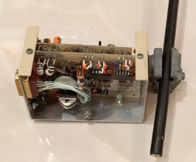
The photo above shows a board with two counters: the two wheels on the left stored two digits. The counters are more complex than you might expect, with electromechanical circuits to handle carries (including fast carry lookahead). The clutch is underneath the wheel and is engaged by the metal levers in the photo, controlled by electromagnets. A gear underneath the clutch connects the counter to the driveshaft. The electrical connections on the right control the clutch and allow the values from the counters to be read out. Since the IBM 405 had 16 accumulators, with up to 8 digits, many counters were required, resulting in the mass of counter wires in the photos.

Relays

Another key component of the accounting machine was the relay, an electromagnetic switch. The control logic of the accounting machine was implemented with hundreds of relays, which would turn on and off to direct the various components of the accounting machine. Example relay functions are switching on when punched cards are in the input hopper, selecting addition or subtraction for a counter, generating the final total when all cards are done, or printing a credit symbol for a negative balance.

The back of the IBM 403 accounting machine shows numerous relays, used to control the machine.

The back of the IBM 403 accounting machine shows numerous relays, used to control the machine.

The relays were mounted on swing-out panels. The photo above shows an IBM 403 with the panels closed. In the Abbott photos the relay panels are opened and you can see the extensive wiring that connected the relays to the rest of the system.

Circuit breakers

The final component I'll explain is the "circuit breaker," which has nothing to do with the circuit breakers in your house. Instead, these are cam-controlled switches that turned on and off (breaking circuits) as the drive shafts rotated. Dozens of circuit breakers provided the timing signals to the accounting machine, ensuring all operations in the machine were synchronized to the drive shaft. (Every 18° of drive shaft rotation corresponded to reading one row on a punched card, moving one character position on a printer typebar, or advancing a counter wheel by one position.)

Conclusion

The woman in Abbott's photos illustrates the large, but mostly ignored role that women played in electrical manufacturing. Women formed the majority of workers in the 1920s radio manufacturing industry, and their presence in electrical manufacturing increased even more when World War II led many women to take industrial jobs. The famous ENIAC computer (1946) also illustrates this: most of the "wiremen" assembling the ENIAC computer were in fact women, probably recruited from the telephone company or radio assembly.8

The photos also provide a glimpse into the era before digital computers, when businesses used electromechanical accounting machines and tabulators for their data processing. Although you'd expect a machine from 1934 to be primitive, the IBM 405 accounting machine in the photos was an advanced piece of technology for its time, containing 55,000 parts and 75 miles of wire.5 These punched card machines were also capable of performing complex scientific tasks, even contributing to the Manhattan Project. In the 1960s, businesses gradually switched from accounting machines to stored-program business computers such as the IBM 1401. Even so, IBM continued marketing accounting machines until 1976.

Follow me on Twitter or RSS to find out about my latest blog posts.

Notes and references

  1. By the "era before computers", I mean before digital electronic computers came along in the 1940s. There's a long history of computing machines, analog computers, and human computers (as shown in Hidden Figures) before digital computers came along. Two interesting books that cover this history are The First Computers—History and Architecture or The Computer: From Pascal to von Neumann

  2. IBM's 402 and 403 accounting machines were the same except the 403 could print three-line addresses. This feature was called MLP (multi-line printing) and was useful for printing addresses on invoices, for instance. So when I refer to the IBM 403 accounting machine, I'm also including the IBM 402. 

  3. I was surprised to realize that there are two different, but nearly identical photos of the woman wiring the IBM machine floating around. In first photo, the woman's right leg is straight, there's a screwdriver in front of the bench and she's wiring the left side of the machine. In the second, the woman's left leg is straight and she's wiring the middle of the machine. 

  4. I couldn't find any manuals for the IBM 405 or photos of the back of a 405, so I can't totally nail down the identification. There's a possibility that the Abbott photos show an IBM 401 accounting machine (below), which was similar to the 405 but introduced a year earlier. The IBM 401 and IBM 405 both had the same basic shape and arrangement of components. The main difference is 405 had a full cabinet in front while the 401 was empty in the front with a bar bracing the front feet. The Abbott photos seem to show a full cabinet like the 405, rather than the open 401. Also, since the 405 was a much more popular machine than the 401—the 405 was the "flagship of IBM's product line until after World War II"—the photos are most likely the 405.

    IBM 401 accounting machine (1933). Photo courtesy of Computer History Museum.

    IBM 401 accounting machine (1933). Photo courtesy of Computer History Museum.

  5. Several sources provide information on the IBM 405. One source is Computing before Computers (online) p144. IBM has a FAQ with a short overview. Columbia's Computer History page on the 405 has a longer discussion. Also see IBM's Early Computers, pages 18-22 for information on the IBM 405. Computer: Bit Slices from a Life has some hands-on stories of the IBM 405 (online). Computer: A history of the information machine page 51 has some information on the IBM 405. 

  6. See Punched Card Methods in Scientific Computation, 1940 for details on how accounting machines were used for scientific computation. The book is by W. J. Eckert, confusingly unrelated to the ENIAC's J. Presper Eckert. The use of IBM accounting machine by the Manhattan Project is described by Feynman in Los Alamos from Below, p25; and in this page. The Manhattan Project used a 402 accounting machine, several IBM 601 multiplying punches for multiplication, and other card equipment (reference, with more details in Early Computing at Los Alamos). 

  7. Bitsavers has manuals for the later 402/403 accounting machines. The operation of accounting machines is discussed in detail in IBM 402, 403 and 419 Accounting Machines: Manual of Operation. For a thorough discussion of how the machine works internally, see IBM 402, 403, 419 Field Engineering Manual of Instruction. For an overview of how plugboard wiring for IBM's works, see IBM Functional Wiring Principles

  8. Women and Electrical and Electronics Manufacturing provides a detailed discussion of the history of women in technological manufacturing in the 20th century. The book ENIAC in Action describes how most of the wiring of the ENIAC was done by women. It also has a detailed discussion of the role of women as programmers for early computers such as the ENIAC. 

Steve Jobs, the Xerox Alto, and computer typography

Steve Jobs gave an inspirational commencement address at Stanford in 2005. He described how his decision to drop out of college unexpectedly benefitted the Macintosh years later:

Reed College at that time offered perhaps the best calligraphy instruction in the country. [...] Because I had dropped out and didn’t have to take the normal classes, I decided to take a calligraphy class to learn how to do this. I learned about serif and sans serif typefaces, about varying the amount of space between different letter combinations, about what makes great typography great. It was beautiful, historical, artistically subtle in a way that science can’t capture, and I found it fascinating.

None of this had even a hope of any practical application in my life. But 10 years later, when we were designing the first Macintosh computer, it all came back to me. And we designed it all into the Mac. It was the first computer with beautiful typography. If I had never dropped in on that single course in college, the Mac would have never had multiple typefaces or proportionally spaced fonts. And since Windows just copied the Mac, it’s likely that no personal computer would have them. If I had never dropped out, I would have never dropped in on this calligraphy class, and personal computers might not have the wonderful typography that they do.

While this is an uplifting story about trusting in destiny, the real source of this computerized "wonderful typography" is the Xerox Alto computer, built by Xerox PARC in 1973. The Alto was a revolutionary system, one of the first to use a high-resolution bitmapped display, a GUI, and an optical mouse. The first WYSIWYG (What You See Is What You Get) text editor was created at Xerox PARC in 1974 by Charles Simonyi, Butler Lampson and other Xerox researchers. The Alto system supported many high-quality fonts, including proportionally spaced fonts with ligatures.1 Xerox PARC also invented the laser printer in 1971, allowing high-resolution documents to be printed.2

The Xerox Alto displaying Steve Job's commencement speech with fancy formatting in the Bravo editor. That's an old Macintosh 512K in the background.

The Xerox Alto displaying Steve Job's commencement speech with fancy formatting in the Bravo editor. That's an old Macintosh 512K in the background.

Xerox PARC used this software for its Alto documentation, producing high-quality printed manuals that mixed text and computer-generated drawings. The Alto User's Handbook (below), for example, combined nicely-formatted text with computer-generated drawings.6 Thus, by the time Steve Jobs founded Apple in 1976, Xerox had created a high-quality desktop publishing system. Steve Jobs' claim that the Mac (1984) was the first computer with beautiful typography is wrong by about a decade.

The Alto User's Handbook was created using the Alto's desktop publishing software, including Bravo and Draw. The closeup on the right shows how typography was combined with drawings.

The Alto User's Handbook was created using the Alto's desktop publishing software, including Bravo and Draw. The closeup on the right shows how typography was combined with drawings.

Steve Jobs famously visited Xerox PARC in 1979 and saw Xerox's GUI technology. The revolutionary systems he saw there inspired the direction for the Lisa and Macintosh. (This led Xerox to attempt to sue Apple in 1989 for copying its technology.) 5 Jobs later said about Xerox's GUI: "I thought it was the best thing I’d ever seen in my life. [...] And within – you know – ten minutes it was obvious to me that all computers would work like this some day." So although Steve Jobs claimed in his commencement speech, "If I had never dropped in on that single course in college, the Mac would have never had multiple typefaces or proportionally spaced fonts", the Xerox PARC visit appears to be the real source.7

Closeup of Steve Jobs' commencement speech in the Bravo editor on the Xerox Alto. This shows a few of the proportionally-spaced fonts available on the Alto. It also demonstrates centered and  justified text.

Closeup of Steve Jobs' commencement speech in the Bravo editor on the Xerox Alto. This shows a few of the proportionally-spaced fonts available on the Alto. It also demonstrates centered and justified text.

In his commencement address, Steve Jobs also claimed, "And since Windows just copied the Mac, it's likely that no personal computer would have [multiple typefaces or proportionally spaced fonts]." The ironic thing is that Microsoft Word was developed by Charles Simonyi, the same Simonyi who co-wrote Xerox's Bravo editor in 1973. Since the Macintosh came out in 1984, the accusation of copying is directed the wrong way. It's also absurd to claim that no other personal computer would have these features without Jobs, since the Alto had them years earlier.4

Conclusion

While Steve Job's commencement speech is inspiring, it is also an example of the "reality distortion field" at work. While he claimed that a calligraphy course at Reed inspired him to provide typography support in the Macintosh, the Xerox Alto and Jobs' visit to Xerox PARC in 1979 are surely more important. The Macintosh owes everything from the WYSIWYG editor and spline-based fonts to the bitmapped display and laser printer to the Xerox Alto. Of course, Steve Jobs deserves great credit for making desktop publishing common and affordable with the Macintosh and the LaserWriter, something Xerox failed to do with the Xerox Star, an expensive ($75,000) system that commercialized the Alto's technology.

I've been restoring an Alto from YCombinator, along with Marc Verdiell, Carl Claunch and Luca Severini. My full set of Alto posts is here and Marc's extensive videos of the restoration are here. You can follow me on Twitter here for updates on the restoration.

Notes and references

  1. The Alto supported high-quality spline-based fonts, as well as bitmap fonts. PARC built an interactive font editor (FRED) and an interactive rasterizer (PREPRESS). This system is essentially an ancestor of the TrueType fonts used today (details). 

  2. Xerox PARC also invented Press, a device-independent printer file format that eventually led to PDF files. First, Xerox's Press format led to the Interpress product. Two of Interpress's creators left Xerox and started Adobe, where they created the PostScript page definition language. The ubiquitous PDF format is in turn a descendant of PostScript. Some history on Xerox's early printers and Press format is here

  3. In 1975, Xerox PARC developed an improved modeless version of the Bravo editor for use by textbook publisher Ginn & Co., which used this system for the majority of their books. This illustrates that Xerox's desktop publishing was used commercially, not just for research. See Fumbling the Future, Chapter 9 for details. The document Gypsy Evaluation is Xerox's 1976 evaluation of the system. 

  4. While the term "personal computer" is vague, it's clear that the Alto's builders intended it as a personal computer. See for example Alto: A personal computer, Alto: A Personal Computer System Hardware Manual and The Xerox Alto Computer which describes the Alto as a "personal computer to be used for research". 

  5. The details of Steve Jobs' visits to Xerox PARC are highly controversial but the description in Dealers of Lightning seems most accurate. It's well known that as part of Xerox investing in Apple, Steve Jobs arranged to see demos of the PARC technology. However, this didn't include licensing of the technology. 

  6. Examples of documents created with the Xerox Alto are the hardware manual, Alto User's Handbook, and Alto Newsletter

  7. Note that the popular Apple II computer (1977) didn't have beautiful typography or multiple fonts—it didn't even include lower case characters. Lower case support was finally added to the Apple IIe in 1983. 

The Xerox Alto, Smalltalk, and rewriting a running GUI

Be sure to read the comment from Alan Kay at the bottom of the article!

We succeeded in running the Smalltalk-76 language on our vintage Xerox Alto; this blog post gives a quick overview of the Smalltalk environment. One unusual feature of Smalltalk is you can view and modify the system's code while the system is running. I demonstrate this by modifying the scrollbar code on a running system.

Smalltalk is a highly-influential programming language and environment that introduced the term "object-oriented programming" and was the ancestor of modern object-oriented languages.1 The Alto's Smalltalk environment is also notable for its creation of the graphical user interface with the desktop metaphor, icons, scrollbars, overlapping windows, popup menus and so forth. When Steve Jobs famously visited Xerox PARC, the Smalltalk GUI inspired him on how the Lisa and Macintosh should work.2

Our Xerox Alto running Smalltalk-76.

Our Xerox Alto running Smalltalk-76.

The Alto was a revolutionary computer designed at Xerox PARC in 1973 to investigate personal computing. It introduced the GUI, high-resolution bitmapped displays, WYSIWYG editors, Ethernet, the optical mouse and laser printers to the world, among other things. I've been restoring an Alto from YCombinator, along with Marc Verdiell, Carl Claunch My full set of Alto posts is here and Marc's extensive videos of the restoration are here.

The desktop

Smalltalk introduced the desktop metaphor used in modern computing.3 It included overlapping windows4, multiple desktops and pop-up menus. These windows could be moved and resized with the mouse. (The biggest missing desktop feature was desktop icons, which Xerox later introduced in the Star computer.) To understand how revolutionary this was, consider that the Apple 1 microcomputer came out in 1976, displaying 24 lines of 40 uppercase characters. The mainframe and minicomputer worlds were focused around punched cards, line printers, Teletypes, and dumb CRT terminals. Alan Kay changed all this with his vision of a computer desktop with windows that could be directly manipulated, windows containing fancy typography or images.

Smalltalk introduced the desktop environment, with overlapping windows for multiple applications.

Smalltalk introduced the desktop environment, with overlapping windows for multiple applications.

The screenshot above shows the Smalltalk-76 desktop. At the bottom, a drawing program displays the Smalltalk elf image.5 Icons allow selection of drawing mode, line style, brush color (grayscale), and so forth. The Smalltalk class browser is in the middle. In the upper right is a file viewer. Finally, in the upper left is a window for entering Smalltalk statements, essentially a shell or REPL.

Dynamically changing the running system

One of the most interesting things about the Smalltalk environment is that all the Smalltalk code can be examined and modified, even while the system is running. The class browser below lets you select (using the mouse) a functional area such as "Basic Data Structures" or "Files". You can then select a class in that area, functionality within the class, and then a particular method. The browser then displays the code running on the system. All the Smalltalk code can be examined in this way, making the system's implementation very transparent.

Using the Smalltalk class browser, we can view the code to show a ScrollBar.

Using the Smalltalk class browser, we can view the code to show a ScrollBar.

In the screenshot above, I use the class browser to access "Panes and Menus", then "ScrollBar", then "Image" and finally "show". This displays the code for the scrollbar's "show" method, which draws the scrollbar. This code draws a black rectangle, and then insets a white rectangle, resulting in a black-bordered rectangle for the scrollbar. (Note the unusual dotted-circle character ☉ that Smalltalk-76 uses to create a Point from two Numbers.)

The unusual feature of the class browser is that you can use it to change the system's code, while the system is running, and everything will pick up the new code. For example, I can change how scrollbars are drawn. In the screenshot below, I changed clear: white to clear: black. Pressing the middle mouse button pops up a menu, and I can select "compile". This causes the scrollbar code to be recompiled—while the system is still running. (Note the modern appearance of the contextual pop-up menu.)

After changing the code, I selected "compile" from the pop-up menu.

After changing the code, I selected "compile" from the pop-up menu.

The result of this change is that all scrollbars (for existing or new windows) will now have a black background, as you can see below. The key point is this change was made while the system was running; there is no need to restart anything. Even existing windows get the new scrollbars.

Scrollbars now appear with a black background, even for existing windows.

Scrollbars now appear with a black background, even for existing windows.

Although this scrollbar change was rather trivial, major changes can be made to the running Smalltalk system. One well-known story of changing Smalltalk's behavior on the fly is from Steve Jobs' visit to Xerox PARC. Steve Jobs didn't like the way the window scrolled line-by-line, so Smalltalk implementer Dan Ingalls rewrote the scrolling code in a minute and implemented smooth scrolling while the system was running, much to Jobs' surprise.6

A closer look at some Smalltalk code

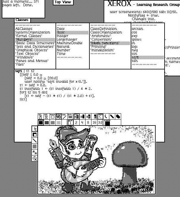
In Smalltalk, even most of the math functions are written in Smalltalk. For instance, suppose we wonder how square roots are computed. We can look at the square root function in the class browser by going to "Numbers", "Float", "Math functions", "sqrt". This brings up the seven lines of code below for the square root function. We can see that the code uses five iterations of Newton's method to approximate the square root.

Looking at the square root code in the Smalltalk-76 class browser.

Looking at the square root code in the Smalltalk-76 class browser.

If you're used to Java or C++, this object-oriented code may look strange, especially since Smalltalk uses some strange characters. The first line of code above defines local variables guess and i. In the next line, the right arrow ⇒ implements an "if" statement. If the number receiving the square root message (self) is 0, then 0 is returned (via the up arrow ⇑ return symbol) and if it is negative an exception is raised. The square brackets define blocks, similar to curly braces in C. The instfield line is a bit tricky; it pulls the exponent out of the floating point number and divides it by 2, yielding a reasonable starting point for the square root. Finally, the for loop applies Newton's method 5 times and returns the result. Note the unusual double colon symbol ⦂; this delays evaluation of the argument, so it can be evaluated multiple times in the loop.7

You might think that executing Smalltalk code for math operations would be very slow, and that is the case. The good news is that basic operations such as addition are implemented with short cuts, rather than full message passing. But other operations are slow; the team described performance as between "majestic" and "glacial". Xerox PARC ended up creating the Dorado, a much faster minicomputer than the Alto, to improve performance.

Conclusion

Although Smalltalk wasn't the first object-oriented programming language, Smalltalk introduced the term object-oriented programming and was very influential in later object-oriented programming languages. Most modern object-oriented languages, from Objective-C and Go to Java and Python, show the influence of Smalltalk. Smalltalk was also responsible for design patterns. The famous "Gang of Four" Design Patterns book describes design patterns in Smalltalk and C++.8

Smalltalk systems are still in use. Smalltalk-76 (and the earlier 71 and 72 versions) were intended for research, but Xerox released the Smalltalk-80 version; it was licensed by Xerox to HP, Apple, Tektronix and DEC for royalty-free distribution. Smalltalk-80 in turn led to modern Smalltalk systems such as Pharo, GNU Smalltalk and Squeak (which led to the Scratch language for children).

If you want to try Alto Smalltalk out for yourself, you can use the Contralto emulator, built by the Living Computers Museum. I explain how to run it here. (Most of the screenshots above are from Contralto rather than the live Alto, for clearer images.) Be warned, however, that Smalltalk on the Alto (live or emulated) is painfully slow.

Follow me on Twitter: @kenshirriff to find out about my latest blog posts. I also have an RSS feed.

Notes and references

  1. Smalltalk was developed on the Xerox Alto by Alan Kay, Dan Ingalls, Adele Goldberg and others. 

  2. The details of Steve Jobs' visits to Xerox PARC are highly controversial but the description in Dealers of Lightning seems most accurate. 

  3. Englebart's Mother of All Demos was fundamental to the development of the GUI, introducing the mouse and windows, among other things. This demo had a large influence on Xerox PARC. 

  4. For performance reasons, only the foreground window was active and background windows were not redrawn. 

  5. Screenshots of Smalltalk-76 very often include the lute-playing elf image, so I tracked down the image and figured out how to display it. The command is BitRect new fromuser; filin: 'elf'; edit. This creates a new BitRect object and gets the dimensions from the user. Then it sends a filin: 'elf' message to the BitRect, which performs file input from the elf.pic file. Finally, an edit message is sent to the BitRect, causing it to be opened in the image editor. 

  6. For details on Dan Ingalls' live implementation of smooth scrolling in Smalltalk-78, see this page. The story is also in Dealers of Lightning, page 341. (Dealers of Lightning is the best book I've come across describing Xerox PARC and the development of the Alto.) 

  7. If you want more information on Smalltalk-76, The Smalltalk-76 Programming System Design and Implementation provides a good overview. The document How to use the Smalltalk-76 system gives details on running Smalltalk on the Alto. Unfortunately, the special characters don't appear, making the document slightly cryptic. See Alan Kay's The Early History of Smalltalk for a detailed discussion of Smalltalk's background and history. 

  8. People often think of design patterns as a Java thing, but the Design Patterns book was published in 1994, prior to Java's release in 1995. The original design patterns referred to C++ and Smalltalk. 

Inside the vintage Xerox Alto's display, a tiny lightbulb keeps it working

In this Alto restoration episode, we repaired a second CRT display, exercising our TV repair skills and discovering a tiny mysterious lightbulb that caused the display to fail in a strange way. For those just tuning in, the Alto was a revolutionary computer designed at Xerox PARC in 1973 to investigate personal computing. It introduced the GUI, high-resolution bitmapped displays, WYSIWYG editors, Ethernet and laser printers to the world, among other things.

The YCombinator Xerox Alto, running a Mandelbrot set program I wrote in BCPL.

The YCombinator Xerox Alto, running a Mandelbrot set program I wrote in BCPL.

I've been restoring an Alto from YCombinator, along with Marc Verdiell, Carl Claunch and Luca Severini. Since we have the YCombinator Alto working (above), we've been trying trying to get a second Xerox Alto system running; this one is from DigiBarn. My full set of Alto posts is here and Marc's videos are here.

Inside the Alto's display

When we tried to connect the DigiBarn display to the Alto, we ran into a problem—it had an incompatible connector. Looking inside the display (below), we were surprised to find this connector led to a circuit board with a 6502 microprocessor; since the Alto came out in 1973 and the 6502 in 1975, this didn't make sense. After some investigation, I determined that although the display looked like an Alto display, it was actually for a Dorado, a Xerox minicomputer from 1979 that followed the Alto.

Inside the Xerox Alto's display. With the cover removed, the CRT and monitor circuitry are visible. The 7-wire interface board is at bottom-left. The Alto itself is in the cabinet under the display.

Inside the Xerox Alto's display. With the cover removed, the CRT and monitor circuitry are visible. The 7-wire interface board is at bottom-left. The Alto itself is in the cabinet under the display.

The Dorado was much faster than the Alto because the Dorado used ECL chips, the same technology used in the Cray-1 supercomputer. Unfortunately, since ECL chips used a lot of power and needed powerful cooling fans, the Dorado was too hot and noisy to use in an office. Putting a soundproof enclosure around the Dorado didn't work, so Xerox ended up putting Dorados in machine rooms. The user's keyboard, mouse and display was connected to the remote Dorado with a special cable using the "7-wire protocol" that Xerox invented for this purpose. The 6502 board was the interface for this protocol. 5

To connect the Alto to this display, I built an adapter cable that bypassed the 7-wire board. We hooked up the monitor, powered it on, and were greeted with a empty black screen. Given the age of the monitor, we weren't surprised that it didn't work. However, when we powered off the monitor, we saw a perfect image for a fraction of a second before the image collapsed to a dot and disappeared. This was unexpected—the monitor didn't work at all when powered on, but worked fine (but very briefly) when turned off! What could be going on?

How a CRT monitor works

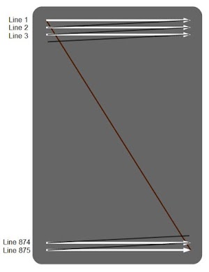
Since many readers may not be familiar with how CRTs work, I'll take a brief detour and explain how CRTs work. The cathode ray tube (CRT) ruled television displays from the 1930s until LCD displays took over about 10 years ago.2 In a CRT, an electron beam is shot at a phosphor-coated screen, causing a spot on the screen to light up. The beam scans across the screen, left to right and top to bottom in a raster pattern. The beam is turned on and off, generating a pattern of dots on the screen to form the image. The horizontal scan will turn out to be very important to this repair.

The Xerox Alto's display uses an 875-line raster scan. (For simplicity, I'm ignoring interlacing of the raster scan.)

The Xerox Alto's display uses an 875-line raster scan. (For simplicity, I'm ignoring interlacing of the raster scan.)

The cathode ray tube is a large vacuum tube containing multiple components, as shown below. A small electrical heater, similar to a light bulb filament, heats the cathode to about 1000°C. The cathode is an electrode that emits electrons when hot. A control grid surrounds the cathode; putting a negative voltage on the grid repels the negatively-charged electrons, reducing the beam strength and thus the brightness. The next grid has about 800 volts on it, attracting and accelerating the electrons. The focus grid, at about 600 volts, squeezes the electron beam to form a sharp spot. The anode is positively charged to a high voltage (17,000V), accelerating the electrons to hit the screen with high energy. The screen is coated with a phosphor, causing it to glow where hit by the electron beam. Finally, two electromagnets are arranged on the neck of the tube to deflect the beam horizontally and vertically in the raster scan pattern shown earlier; these are the deflection coils.

Diagram of a Cathode Ray Tube (CRT). Based on drawings by Interiot and Theresa Knott (CC BY-SA 3.0)

Diagram of a Cathode Ray Tube (CRT). Based on drawings by Interiot and Theresa Knott (CC BY-SA 3.0)

The photo below shows the Cathode Ray Tube (CRT) inside the Alto's monitor, with the screen at the right. In the center, the red deflection coils are mounted on the neck of the tube. The thick red wire provides 17,000 volts to the anode. This high voltage is generated by the flyback transformer, the UFO-like gray disk in the lower left.

Inside the Xerox Alto's display, the CRT picture tube is visible. The thick red wire provides 17,000 volts from the flyback transformer to the tube's anode. The other red wire is connected to the 500MΩ 6W bleeder resistor, the large white cylinder at the left. Note the dirt and debris on the flyback transformer from the system's storage in a barn.

Inside the Xerox Alto's display, the CRT picture tube is visible. The thick red wire provides 17,000 volts from the flyback transformer to the tube's anode. The other red wire is connected to the 500MΩ 6W bleeder resistor, the large white cylinder at the left. Note the dirt and debris on the flyback transformer from the system's storage in a barn.

Back to the broken display

Why would the display work for a moment, just as it is powered off? It must have something to do with voltage levels dropping as the power supplies shut down—something that wasn't working at full voltage, but worked at a lower voltage. One theory was that one of the CRT grids might have the wrong voltage. Since electrons are negative, they are attracted to positive voltages (such as the 17,000 volt anode) and repelled by negative voltages. If a grid was too negative, the electron beam could be blocked. Perhaps as the power supplies shut down, the negative grid problem briefly resolved itself.3

We opened up the display and measured some voltages, taking extreme care around the high voltages. Verifying the 17,000 V supply was easy; with a voltage this high, waving an oscilloscope probe a few inches away is sufficient to pick up a signal (below). The main 55V supply was also good. But when we checked the grid voltages, we didn't get anything.

The service manual shows the waveform you can pick up two inches away from the flyback transformer.

The service manual shows the waveform you can pick up two inches away from the flyback transformer.

The grid voltages and 17KV supply are generated by the flyback transformer. Since we saw the 17KV signal, we knew the horizontal deflection circuit and the flyback transformer were working. Perhaps a capacitor had failed, but we didn't find any bad ones. On the schematic we noticed a tiny lightbulb in the high-voltage circuit, an unexpected circuit element. We measured the bulb's resistance on the board (below) and found it was open. We figured the bulb must have burned out, but after removing it we discovered that instead one of the bulb's leads had broken off right at the glass case.

The bulb is visible in front of the right side of the transformer.

The bulb is visible in front of the right side of the transformer.

The service manual for the monitor called the bulb a "No. 1764." I was afraid that this was an internal part number and we wouldn't be able to determine the correct replacement bulb. However, Google revealed that this was a 28V 0.04A miniature bulb, sold by many vendors. Unfortunately we couldn't find any local stores that sold this bulb and we wanted to test out a fix immediately. So Marc performed some precision microscope soldering to reattach the broken wire. Since the wire had broken off right at the glass, reattaching it was very difficult but he succeeded. We re-installed the bulb and the display worked fine!

Why is there a bulb inside the power supply? I assume that it is used as a current limiter. Bulbs have very low resistance when cold, but increase resistance as they warm up. It seems crazy to subject a 28 V bulb to pulses of 600 volts, but since the pulses are only a few microseconds, the bulb survives them just fine.

The tiny bulb inside the display's power supply.

The tiny bulb inside the display's power supply.

Details on the power supply

The high-voltage power supply is described in the monitor service manual, but I'll give a brief summary here.4

The primary purpose of the horizontal sync circuit is to create a sawtooth current through the horizontal deflection coil to scan left-to-right across each row of the screen. A common trick in TVs is to use the high-frequency (26 kHz) horizontal sync to generate high voltages. To do this, the horizontal sync circuit sends high-current pulses (2-3 amps) through the flyback transformer. This step-up transformer produces the 17 kilovolts required by the CRT's anode. A second transformer winding produces -100 volts, while the third winding is used to generate 600V and 1000V. (Interestingly, cell phone chargers also use flyback transformers, but obviously at much lower voltages.)

The photo below shows the flyback transformer (left). The thick black wire at the bottom of the photo connects the 17KV from the transformer to the picture tube, while the colorful wires at the top provide the lower voltages.

Flyback transformer inside the monitor. The large white cylinder is a 500 megaohm, 6W resistor. You don't usually see such a high resistance combined with a high wattage, but the resistor bleeds off the high voltage from the CRT.

Flyback transformer inside the monitor. The large white cylinder is a 500 megaohm, 6W resistor. You don't usually see such a high resistance combined with a high wattage, but the resistor bleeds off the high voltage from the CRT.

The schematic below indicates the key components of the power supply. The switching transistor is driven by the horizontal sync input. When it switches on, current (red line) builds up in the flyback transformer, storing energy in the transformer's magnetic field. When the transistor switches off, this stored energy is released into the secondary windings, producing 17KV for the anode and -100V for the brightness grid. In addition, a 600V pulse is created across the primary. The pulse (yellow line) flows through the bulb and a diode, generating 600V for the focus grid. The voltage doubler circuit (circled in pink) generates 1000V for the second (accelerator) grid.

The high-voltage power supply is driven by the horizontal deflection circuit.
The switching transistor puts 55 volts across the flyback transformer. When it switches off, the flyback transformer produces 17 kilovolts for the CRT anode, as well as powering the 600V, 1000V and -100V supplies.

The high-voltage power supply is driven by the horizontal deflection circuit. The switching transistor puts 55 volts across the flyback transformer. When it switches off, the flyback transformer produces 17 kilovolts for the CRT anode, as well as powering the 600V, 1000V and -100V supplies.

Why did the display originally show a picture for a moment as it was powered off? With the bulb not working, the 800V acceleration grid and the focus grid didn't receive any voltage, but the brightness grid was still powered (since -100V comes from a different winding). My theory is that without the attraction from the acceleration grid, electrons couldn't get past the negative brightness grid. But when the brightness grid lost power, the electron beam was no longer blocked and could reach the screen, until everything else shut down moments later.

Conclusion

Cathode ray tubes were the dominant display technology until LCD displays took over about 10 years ago. Now, CRT TV repair is a retro activity, involving circuits such as horizontal deflection, video amplifiers, and high-voltage flyback transformers that were formerly well-known but are now more obscure.

We tracked down the display's problem to a tiny light bulb, an unusual component to find in a critical role in a high-voltage power supply. Surprisingly, despite being exposed to 600 volt pulses, the problem with this 28 volt bulb wasn't that it had burnt out, but that one of its tiny leads had broken. After repairing the bulb, the display worked fine. Unlike our previous display which had a very faint CRT, this one produced a crisp, bright image. Since we got the display working and didn't get any high-voltage shocks, I consider this a successful restoration session.

The repaired display shows a test pattern, generated by the crttest program. The screen is bright and sharp, but the horizontal centering still needed adjustment.

The repaired display shows a test pattern, generated by the crttest program. The screen is bright and sharp, but the horizontal centering still needed adjustment.

Thanks to the Living Computer Museums + Lab for providing the display test board. Thanks to Al Kossow and Bitsavers for the scanned service manual.

Notes and references

  1. For more on the Alto's monitor, see my article from last year about restoring our first display

  2. A computer monitor is essentially a television set, but without the tuner to select the desired channel from the antenna. In addition, televisions have circuitry to extract the horizontal sync, vertical sync and video signals from the combined broadcast signal. These three signals are supplied to the Alto monitor separately, simplifying the circuitry. 

  3. I should admit that Marc and Carl had the right theory about the problem. My theory that the video input voltage might be too high didn't pan out. 

  4. I didn't discuss the 55V supply that powers the monitor. It is a straightforward regulated linear power supply driven from the 120V AC input. I also also didn't explain how the horizontal deflection coil operates. it is driven by the same transistor as the flyback transformer, but uses a fairly complex inductor-capacitor resonance circuit to generate the scan across the screen. (The scan current is a sawtooth; a smooth scan left-to-right followed by a rapid retrace back to the left.) For a thorough discussion of how the display's power supply works, see page 3-4 of the service manual

  5. The 7-wire interface used a 15-wire cable with standard DB-15 (serial port) connectors. It sent seven ECL signals as differential pairs, and used the remaining wire for ground. Calling it "7-wire" seems a bit misleading, since it used 15 wires in total. The board schematic is in the Dorado schematics page 159. The video signal was multiplexed across four of the signals; this reduced the bandwidth requirement by a factor of four. One signal was serial data; this transmitted the keyboard and mouse information. The remaining two signals were (apparently redundant) clocks. The protocol supported daisy-chaining, so multiple peripherals (such as a printer) could be connected.

    This 7-wire Terminal Interface board was used by Xerox PARC to connect a keyboard/display/mouse to a remote Dorado minicomputer

    This 7-wire Terminal Interface board was used by Xerox PARC to connect a keyboard/display/mouse to a remote Dorado minicomputer

    The photo above shows the 7-wire terminal interface board inside the display. The large chips in the upper right are the 6532 "RIOT" I/O chip, the 6502 microprocessor, and a 2716 EPROM holding the code. The remaining chips are a mixture of TTL and ECL. At the bottom are connectors for 7-wire in, 7-wire out, and the keyboard. The connector to the monitor itself is in the upper center.