Almost every smartphone uses a processor based on the ARM1 chip created in 1985.
The
Visual ARM1 simulator shows what happens inside the ARM1 chip as it runs; the result (below) is fascinating but mysterious.
[1]
In this article, I reverse engineer key parts of the chip and explain how they work, bridging the
gap between the puzzling flashing lines in the simulator and what the chip is actually doing.
I describe the overall structure of the chip and then descend to the individual transistors, showing how they are built out of silicon and work together to store and process data.
After reading this article, you can look at the chip's circuits and understand the data they store.

Screenshot of the
Visual ARM1 simulator, showing the activity inside the ARM1 chip as it executes a program.
Overview of the ARM1 chip
The ARM1 chip is built from functional blocks, each with a different purpose. Registers store data, the ALU (arithmetic-logic unit) performs simple arithmetic, instruction decoders determine how to handle each instruction, and so forth. Compared to most processors, the layout of the chip is simple, with each functional block clearly visible. (In comparison, the layout of chips such as the 6502 or Z-80 is highly hand-optimized to avoid any wasted space. In these chips, the functional blocks are squished together, making it harder to pick out the pieces.)
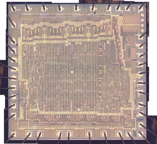
The diagram below shows the most important functional blocks of the ARM chip.[2]
The actual processing happens in the bottom half of the chip, which implements the data path. The chip operates on 32 bits at a time so it is structured as 32 horizontal layers: bit 31 at the top, down to bit 0 at the bottom. Several data buses run horizontally to connect different sections of the chip.
The large register file, with 25 registers, stands out in the image. The Program Counter (register 15) is on the left of the register file and register 0 is on the right.[3]
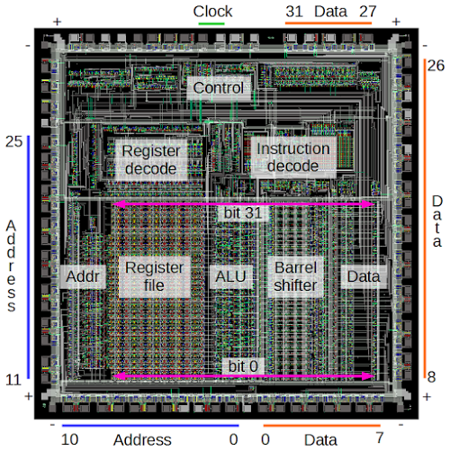
The main components of the ARM1 chip. Most of the pins are used for address and data lines; unlabeled pins are various control signals.
Computation takes place in the ALU (arithmetic-logic unit), which is to the right of the registers. The ALU performs 16
different operations (add, add with carry, subtract, logical AND, logical OR, etc.) It takes two 32-bit inputs and produces a 32-bit output. The ALU is described in detail here.[4]
To the right of the ALU is the 32-bit barrel shifter. This large component performs a binary shift or rotate operation on its input, and is described in more detail below.
At the left is the address circuitry which provides an address to memory through the address pins. At the right data circuitry reads and writes data values to memory.
Above the datapath circuitry is the control circuitry. The control lines run vertically from the control section to the data path circuits below. These signals select registers, tell the ALU what operation to perform, and so forth.
The instruction decode circuitry processes each instruction and generates the necessary control signals. The register decode block processes the register select bits in an instruction and generates the control signals to select the desired registers.[5]
The pins
The squares around the outside of the image above are the pads that connect the processor to the outside world.
The photo below shows the 84-pin package for the ARM1 processor chip. The gold-plated pins are wired to the pads on the silicon chip inside the package.
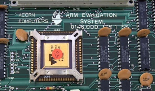
Most of the pads are used for the address and data lines to memory.
The chip has 26 address lines, allowing it to access 64MB of memory, and has 32 data lines, allowing it to read or write 32 bits at a time. The address lines are in the lower left and the data lines are in the lower right.
As the simulator runs, you can see the address pins step through memory and the data pins read data from memory. The right hand side of the simulator shows the address and data values in hex, e.g. "A:00000020 D:e1a00271". If you know hex, you can easily match these values to the pin states.
Each corner of the chip has a power pin (+) and a ground pin (-), providing 5 volts to run the chip.
Various control signals are at the top of the chip. In the simulator, it is easy to spot the the two clock signals that step the chip through its operations (below). The phase 1 and phase 2 clocks alternate, providing a tick-tock rhythm to the chip. In the simulator, the clock runs at a couple cycles per second, while the real chip has a 8MHz clock, more than a million times faster.
Finally, note below the manufacturer's name "ACORN" on the chip in place of pin 82.

The two clock signals for the ARM1 processor chip.
History of the ARM chip
The ARM1 was designed in 1985 by engineers Sophie Wilson (formerly Roger Wilson) and Steve Furber of Acorn Computers.
The chip was originally named the
Acorn RISC Machine and intended as a coprocessor for the
BBC Micro home/educational computer to improve its performance.
Only a few hundred ARM1 processors were fabricated, so you might expect
ARM to be a forgotten microprocessor, a historical footnote of the 1980s.
However, the original ARM1 chip led to the amazingly successful
ARM architecture with more than 50 billion ARM chips produced. What happened?
In the early 1980s, academic research suggested that instead of making processor instruction sets more complex, designers would get better performance from a processor that was simple but fast: the Reduced Instruction Set Computer or RISC.[6]
The Berkeley and Stanford research papers on RISC inspired the ARM designers to choose a RISC design. In addition, given the small size of the design team at Acorn, a simple RISC chip was a practical choice.[7]
The simplicity of a RISC design is clear when comparing the ARM1 and Intel's 80386, which came out the same year:
the ARM1 had about 25,000 transistors versus 275,000 in the 386.[8]
The photos below show the two chips at the same scale; the ARM1 is 50mm2 compared to 104mm2 for the 386.
(Twenty years later, an ARM7TDMI core was 0.1mm2; magnified at the same scale it would be the size of this square
vividly illustrating Moore's law.)
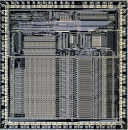
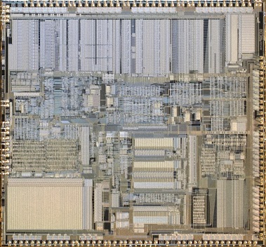
Die photos of the ARM1 processor and the Intel 386 processor to the same scale.
The ARM1 is much smaller and contained 25,000 transistors compared to 275,000 in the 386.
The 386 was higher density, with a 1.5 micron process compared to 3 micron for the ARM1.
ARM1 photo courtesy of
Computer History Museum.
Intel A80386DX-20 by
Pdesousa359,
CC BY-SA 3.0.
Because of the ARM1's small transistor count, the chip used very little power: about 1/10 Watt, compared to nearly 2 Watts for the 386.
The combination of high performance and low power consumption made later versions of ARM chip very popular for embedded systems. Apple chose the ARM processor for its ill-fated Newton handheld system and
in 1990, Acorn Computers, Apple, and chip manufacturer VLSI Technology formed the company Advanced RISC Machines to continue ARM development.[9]
In the years since then, ARM has become the world's most-used instruction set with more than 50 billion ARM processors manufactured. The majority of mobile devices use an ARM processor; for instance, the Apple A8 processor inside iPhone 6 uses the 64-bit ARMv8-A.
Despite its humble beginnings, the ARM1 made IEEE Spectrum's list of 25 microchips that shook the world
and PC World's 11 most influential microprocessors of all time.
Looking at the low-level construction of the ARM1 chip
Getting back to the chip itself, the ARM1 chip is constructed from five layers.
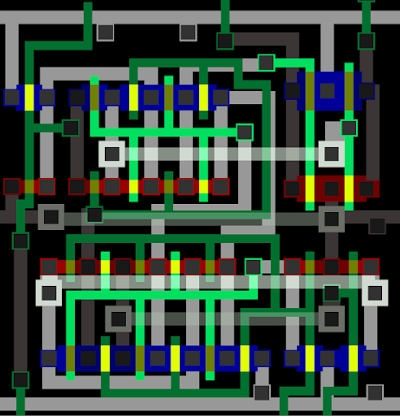
If you zoom in on the chip in the simulator, you can see the components of the chip, built from these layers.
As seen below, the simulator uses a different color for each layer, and highlights circuits that are turned on.
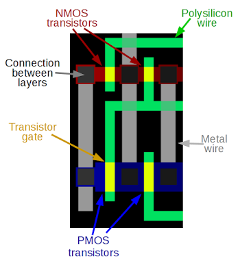
The bottom layer is the silicon that makes up the transistors of the chip.
During manufacturing, regions of the silicon are modified (doped) by applying different impurities. Silicon can be doped positive to form a PMOS transistor (blue) or doped negative for an NMOS transistor (red). Undoped silicon is basically an insulator (black).
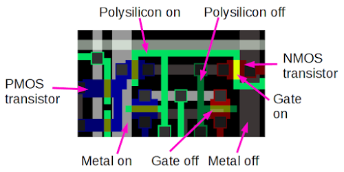
The ARM1 simulator uses different colors to represent the different layers of the chip.
Polysilicon wires (green) are deposited on top of the silicon. When polysilicon crosses doped silicon, it forms the gate of a transistor (yellow).
Finally, two layers of metal (gray) are on top of the polysilicon and provide wiring.[10]
Black squares are contacts that form connections between the different layers.
For our purposes, a MOS transistor can be thought of as a switch, controlled by the gate. When it is on (closed), the source and drain silicon regions are connected. When it is off (open), the source and drain are disconnected. The diagram below shows the three-dimensional structure of a MOS transistor.
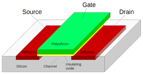
Structure of a MOS transistor.
Like most modern processors, the ARM1 was built using CMOS technology, which uses two types of transistors: NMOS and PMOS.
NMOS transistors turn on when the gate is high, and pull their output towards ground.
PMOS transistors turn on when the gate is low, and pull their output towards +5 volts.
Understanding the register file
The register file is a key component of the ARM1, storing information inside the chip.
(As a RISC chip, the ARM1 makes heavy use of its registers.)
The register file consists of 25 registers, each holding 32 bits. This section describes step-by-step how the register file is built out of individual transistors.
The diagram below shows two transistors forming an inverter. If the input is high (as below), the NMOS transistor (red) turns on, connecting ground to the output so the output is low. If the input is low, the PMOS transistor (blue) turns on, connecting power to the output so the output is high. Thus, the output is the opposite of the input, making an inverter.
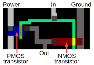
An inverter in the ARM1 chip, as displayed by the simulator.
Combining two inverters into a loop forms a simple storage circuit. If the first inverter outputs 1, the second inverter outputs 0, causing the first inverter to output 1, and the circuit is stable. Likewise, if the first inverter outputs 0, the second outputs 1, and the circuit is again stable. Thus, the circuit will remain in either state indefinitely, "remembering" one bit until forced into a different state.
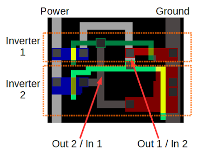
Two inverters in the ARM1 chip form one bit of register storage.
To make this circuit into a useful register cell, read and write bus lines are added, along with select lines to connect the cell to the bus lines.
When the write select line is activated, the pass connector connects the write bus to the inverter, allowing a new value to be overwrite the current bit.
Likewise, pass transistors connect the bit to a read bus when activated by the corresponding select line, allowing the stored value to be read out.
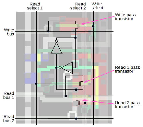
Schematic of one bit in the ARM1 processor's register file.
To create the register file, the register cell above is repeated 32 times vertically for each bit, and 25 times horizontally to form each register.
Each bit has three horizontal bus lines — the write bus and the two read buses — so there are 32 triples of bus lines. Each register has three vertical control lines — the write select line and two read select lines — so there are 25 triples of control lines. By activating the desired control lines, two registers can be read and one register can be written at a time.[11]
When the simulator is running, you can see the vertical control lines activated to select registers, and you can see the data bits flowing on the horizontal bus lines.
By looking at a memory cell in the simulator, you can see which inverter is on and determine if the bit is a 0 or a 1.
The diagram below shows a few register bits. If the upper inverter input is active, the bit is 0; if the lower inverter input is active, the bit is 1.
(Look at the green lines above or below the bit values.) Thus, you can read register values right out of the simulator if you look closely.
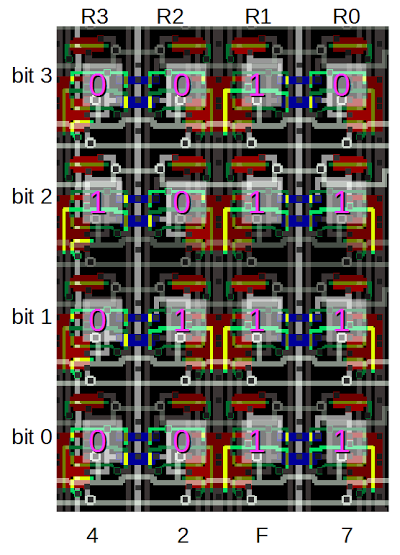
By looking at the ARM1 register file, you can determine the value of each bit. For a 0 bit, the input to the top inverter is active (green/yellow); for a 1 bit, the input to the bottom inverter is active.
The barrel shifter
The barrel shifter, which performs binary shifts, is another interesting component of the ARM1.
Most instructions use the barrel shifter, allowing a binary argument to be shifted left, shifted right, or rotated by any amount (0 to 31 bits).
While running the simulator, you can see diagonal lines jumping back and forth in the barrel shifter.
The diagram below shows the structure of the barrel shifter.
Bits flows into the shifter vertically with bit 0 on the left and bit 31 on the right. Output bits leave the shifter horizontally with bit 0 on the bottom and bit 31 on top. The diagonal lines visible in the barrel shifter show where the vertical lines are connected to the horizontal lines, generating a shifted output. Different positions of the diagonals result in different shifts.
The upper diagonal line shifts bits to the left, and the lower diagonal line shifts bits to the right. For a rotation, both diagonals are active; it may not be immediately obvious but in a rotation part of the word is shifted left and part is shifted right.
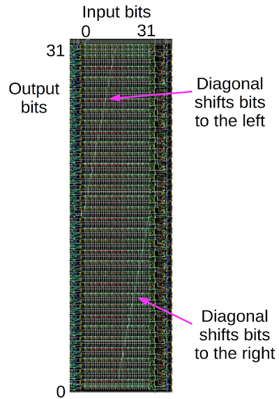
Structure of the barrel shifter in the ARM1 chip.
Zooming in on the barrel shifter shows exactly how it works. It contains a 32 by 32 crossbar grid of transistors, each connecting one vertical line to one horizontal line. The transistor gates are connected by diagonal control lines; transistors along the active diagonal connect the appropriate vertical and horizontal lines.
Thus, by activating the appropriate diagonals, the output lines are connected to the input lines, shifted by the desired amounts.
Since the chip's input lines all run horizontally, there are 32 connections between input lines and the corresponding vertical bit lines.
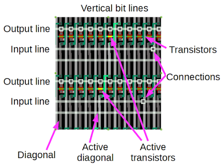
Details of the barrel shifter in the ARM1 chip. Transistors along a specific diagonal are activated to connect the vertical bit lines and output lines. Each input line is connected to a vertical bit line through the indicated connections.
The demonstration program
When you run the simulator, it executes a short hardcoded program that performs shifts of increasing amounts. You don't need to understand the code, but if you're curious it is:
0000  E1A0100F mov     r1, pc        @ Some setup
0004  E3A0200C mov     r2, #12
0008  E1B0F002 movs    pc, r2
000C  E1A00000 nop
0010  E1A00000 nop
0014  E3A02001 mov     r2, #1        @ Load register r2 with 1
0018  E3A0100F mov     r1, #15       @ Load r1 with value to shift
001C  E59F300C ldr     r3, pointer
    loop:
0020  E1A00271 ror     r0, r1, r2    @ Rotate r1 by r2 bits, store in r0
0024  E2822001 add     r2, r2, #1    @ Add 1 to r2
0028  E4830004 str     r0, [r3], #4  @ Write result to memory
002C  EAFFFFFB b       loop          @ Branch to loop
Inside the loop, register r1 (0x000f) is rotated to the right by r2 bit positions and the result is stored in register r0.
Then r2 is incremented and the shift result written to memory.
As the simulator runs, watch as r2 is incremented and as r0 goes through the various values of 4 bits rotated. The A and D values show the address and data pins as instructions are read from memory.
The changing shift values are clearly visible in the barrel shifter, as the diagonal line shifts position. If you zoom in on the register file, you can read out the values of the registers, as described earlier.
Conclusion
The ARM1 processor led to the amazingly successful ARM processor architecture that powers your smart phone. The simple RISC architecture of the ARM1 makes the circuitry of the processor easy to understand, at least compared to a chip such as the 386.
[12]
The ARM1 simulator provides a fascinating look at what happens inside a processor, and hopefully this article has helped explain what you see in the simulator.
P.S. If you want to read more about ARM1 internals, see Dave Mugridge's series of posts:
Inside the armv1 Register Bank
Inside the armv1 Register Bank - register selection
Inside the armv1 Read Bus
Inside the ALU of the armv1 - the first ARM microprocessor
Notes and references
[1]
I should make it clear that I am not part of the Visual 6502 team that built the ARM1 simulator.
More information on the simulator is in the Visual 6502 team's blog post
The Visual ARM1.
[2]
The block diagram below shows the components of the chip in more detail.
See the ARM Evaluation System manual for an explanation of each part.
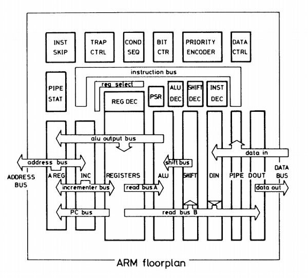
Floorplan of the ARM1 chip, from ARM Evaluation System manual. (Bus labels are corrected from original.)
[3]
You may have noticed that the ARM architecture describes 16 registers, but the chip has 25 physical registers.
There are 9 "extra" registers because there are extra copies of some registers for use while handling interrupts.
Another interesting thing about the register file is the PC register is missing a few bits. Since the ARM1 uses 26-bit addresses, the top 6 bits are not used. Because all instructions are aligned on a 32-bit boundary, the bottom two address bits in the PC are always zero. These 8 bits are not only unused, they are omitted from the chip entirely.
[4]
The ALU doesn't support multiplication (added in ARM 2) or division (added in ARMv7).
[5]
A bit more detail on the decode circuitry.
Instruction decoding is done through three separate PLAs.
The ALU decode PLA generates control signals for the ALU based on the four operation bits in the instruction. The shift decode PLA generates control signals for the barrel shifter. The instruction decode PLA performs the overall decoding of the instruction.
The register decode block consists of three layers. Each layer takes a 4-bit register id and activates the corresponding register. There are three layers because ARM operations use two registers for inputs and a third register for output.
[6]
In a RISC computer, the instruction set is restricted to the most-used instructions, which are optimized for high performance and can typically execute in a single clock cycle.
Instructions are a fixed size, simplifying the instruction decoding logic.
A RISC processor requires much less circuitry for control and instruction decoding, leaving more space on the chip for registers. Most instructions operate on registers, and only load and store instructions access memory.
For more information on RISC vs CISC,
see RISC architecture.
[7]
For details on the history of the ARM1, see Conversation with Steve Furber: The designer of the ARM chip shares lessons on energy-efficient computing.
[8]
The 386 and the ARM1 instruction sets are different in many interesting ways.
The 386 has instructions from 1 byte to 15 bytes, while all ARM1 instructions are 32-bits long.
The 386 has 15 registers - all with special purposes, while the ARM1 has 25 registers, mostly general-purpose.
386 instructions can usually operate on memory, while ARM1 instructions operate on registers except for load and store.
The 386 has about 140 different instructions, compared to a couple dozen in the ARM1 (depending how you count).
Take a look at the 386 opcode map to see how complex decoding a 386 instruction is.
ARM1 instructions fall into 5 categories and can be simply decoded.
(I'm not criticizing the 386's architecture, just pointing out the major architectural differences.)
See the Intel 80386 Programmer's Reference Manual
and 80386 Hardware Reference Manual
for more details on the 386 architecture.
[9]
Interestingly the ARM company doesn't manufacture chips. Instead, the ARM intellectual property is licensed to hundreds of different companies that build chips that use the ARM architecture.
See The ARM Diaries: How ARM's business model works for information on how ARM makes money from licensing the chip to other companies.
[10]
The first metal layer in the chip runs largely top-to-bottom, while the second metal layer runs predominantly horizontally.
Having two layers of metal makes the layout much simpler than single-layer processors such as the 6502 or Z-80.
[11]
In the register file, alternating bits are mirrored to simplify the layout.
This allows neighboring bits to share power and ground lines.
The ARM1's register file is triple-ported, so two register can be read and one register written at the same time. This is in contrast to chips such as the 6502 or Z-80, which can only access registers one at a time.
[12]
For more information on the ARM1 internals, the book
VLSI Risc Architecture and Organization by
ARM chip designer Steven Furber has a hundred pages of information on the ARM chip internals.
An interesting slide deck is A Brief History of ARM by Lee Smith, ARM Fellow.
