Inside the ALU of the 8085 microprocessor

The arithmetic-logic unit is a fundamental part of any computer, performing addition, subtraction, and logic operations, but how it works is a mystery to many people. I've reverse-engineered the ALU circuit from the 8085 microprocessor and explain how it works. The 8085's ALU is a surprisingly complex circuit that at first looks like a mysterious jumble of gates, but it can be understood if you don't mind diving into some Boolean logic.

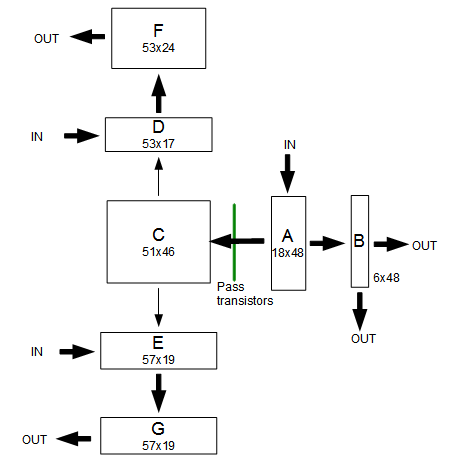
The following diagram shows the location of the ALU in the 8085. The ALU is 8 bits wide, with the high-order bit on the left. The register file is the large block below the ALU. The registers are 16 bits wide, made up of pairs of 8-bit registers. Surprisingly, the register file has the high-order bit on the right, the opposite order from the ALU.

The 8085 microprocessor, showing the location of the 8-bit ALU.

The ALU takes two 8-bit inputs, which I'll call A and X, and performs one of five basic operations: ADD, OR, XOR, AND, and SHIFT-RIGHT. As well, if the input X is inverted, the ALU can perform subtraction and complement operations. You might think SHIFT-LEFT is missing from this list. However, it is simply performed by adding the number to itself, which shifts it to the left one bit in binary. Note that the 8085 arithmetic operations are very basic. There is no multiplication or division operation - these were added in the 8086.

The ALU consists of 8 mostly-identical slices, one for each bit. For addition, each slice of the ALU adds the appropriate input bits, computing the sum A + X + carry-in, generating a sum bit and a carry-out bit. That is, each bit of the ALU implements a full adder. The logic operations simply operate on the two input bits: A AND X, A OR X, A XOR X. Shift-right simply outputs the A bit from the slice to the right.

ALU schematic

The following schematic shows one bit of the ALU. The schematic has roughly the same layout as the implementation on the chip, flowing from bottom to top. Eight of these circuits are stacked side-by-side, with the low-order bit on the right. Carries flow from right to left, and bits shifted right flow from left to right.

Schematic of one bit of the ALU in the 8085 microprocessor.

Negation

Starting at the bottom of the schematic, is the complex gate labeled Negation. This gate optionally selects a negated second argument by selecting either XN or /XN. (XN is the Nth bit of the second argument, which I'll call X. The / indicates the complement.) For most of the discussion below I'll assume XN is uncomplemented to keep things simpler.

Operation

Above the complement selector are a few gates labeled Operation that perform the desired 2-input operation. The NAND gate on the left generates either A NAND X or 1 based on the select_op1 control line. The OR gate on the right generates either A OR X or 1, based on the select_op2 control line. Combining these in the NAND gate yields four different possibilities:
select_op1select_op2Result
00A NOR X
010
10A NXOR X
11A AND X
Note that instead of OR and XOR, the complemented value is produced by this circuit. This will be fixed in the next step.

Combine with carry

Above the operation circuit is the next block of gates labeled Combine with carry that generates the ALU output by merging the carry-in with the operation value via XOR.

To understand this circuit, first consider the following simple XOR circuit, which is used a couple times in the ALU. It can be understood fairly simply: if both inputs are 0 (top) or both inputs are 1 (bottom) then the output is 0.

An XOR gate can be implemented by a NOR gate and an AND-NOR gate. This circuit is used in the 8085 ALU.

Ignoring the shift_right circuit for a moment, the block of gates is simply the XOR circuit above. Note that XOR with 0 is a no-op, while XOR with 1 complements the value. And A XOR X XOR CARRY is the low-order bit of adding A, X, and CARRY.

The key point of this circuit is that the incoming carry is generated with the proper value to convert the operation output into the desired final result. The incoming carry /carry(N-1) is either 0, 1, or the complemented carry from bit N-1 as appropriate.

OpOperation outputCarryResult
orA NOR X1A OR X
addA NXOR X/carryA XOR X XOR CARRY
xorA NXOR X1A XOR X
andA AND X0A AND X
shift right00A(N+1)
complementA NOR /X1A OR /X
subtractA NXOR /X/carryA XOR /X XOR CARRY

Note that the carry-in line must have the right value in order to generate the appropriate output. For addition it passes the inverted carry from one bit to the next. But for OR, XOR, the line is set to 1. And for AND and SHIFT_RIGHT it is set to 0. As will be seen below, the carry circuitry generates the right value for the right operation.

The final aspect of this circuit is the shift-right circuit. With a 0 op input, 0 carry input, and shift_right set, the output is simply the bit from the right: A(N+1).

Generate carry

The circuit on the left, labeled Generate carry generates the carry out. It can generate three different outputs: 1, 0, or the (complemented) carry from the sum. If select_op2 is set, it will force the carry to 0. Otherwise if force_ncarry_1 is set, it will force the carry to 1. Otherwise, the carry is generated for the sum of A + X + carry-in through straightforward logic: If the carry-in is set, and one of the inputs is set, there will be a carry out. If both input bits are set, there will be a carry out.

Flags

The 8085 has a parity flag, which is 1 if the number of 1 bits is even, and 0 if the number of parity bits is odd. The parity flag is generated by XORing all the result bits together (and complementing). Each bit is XORed with the lower-order parity value by the parity circuit near the top of the schematic. The XOR circuit is the same circuit described above.

The zero flag is computed by a simple circuit: each result bit drives a transistor that will pull the zero line low if the bit is set. This forms an 8-input NOR gate, spread across the ALU.

The control lines

As seen in the schematic, the 8085 uses multiple control lines to control the activity inside the ALU. In total, the ALU provides 7 different operations and the following table summarizes the control lines that are used for each operation. It also lists the opcodes that use each ALU operation.

Operationselect_negselect_op1select_op2shift_rightforce_ncarry_1Opcodes
or00001ORA,ORI (and default)
add01000INR,DCR,RLC,DAD,RAL,DAA,ADD,ADC,ADI,ACI (and undocumented LDSI,LDHI,RDEL)
xor01001XRA,XRI
and01101ANA,ANI
shift right00111RRC,RAR (ARHL)
complement10001CMA
subtract11000SUB,SBB,SUI,SBI,CMP,CPI (DSUB)

The ALU control lines are generated from the opcode by the programmable logic array. Specifically, they are outputs from PLA F, which is to the right of the ALU. More details are in my article on the PLA. The ALU has additional control lines to set up the registers, initialize the carry bits, and set the flags. These control the differences between different op codes, beyond the categories above. the I will explain those in a future article.

The PLA in the 8085

Reverse-engineering the ALU

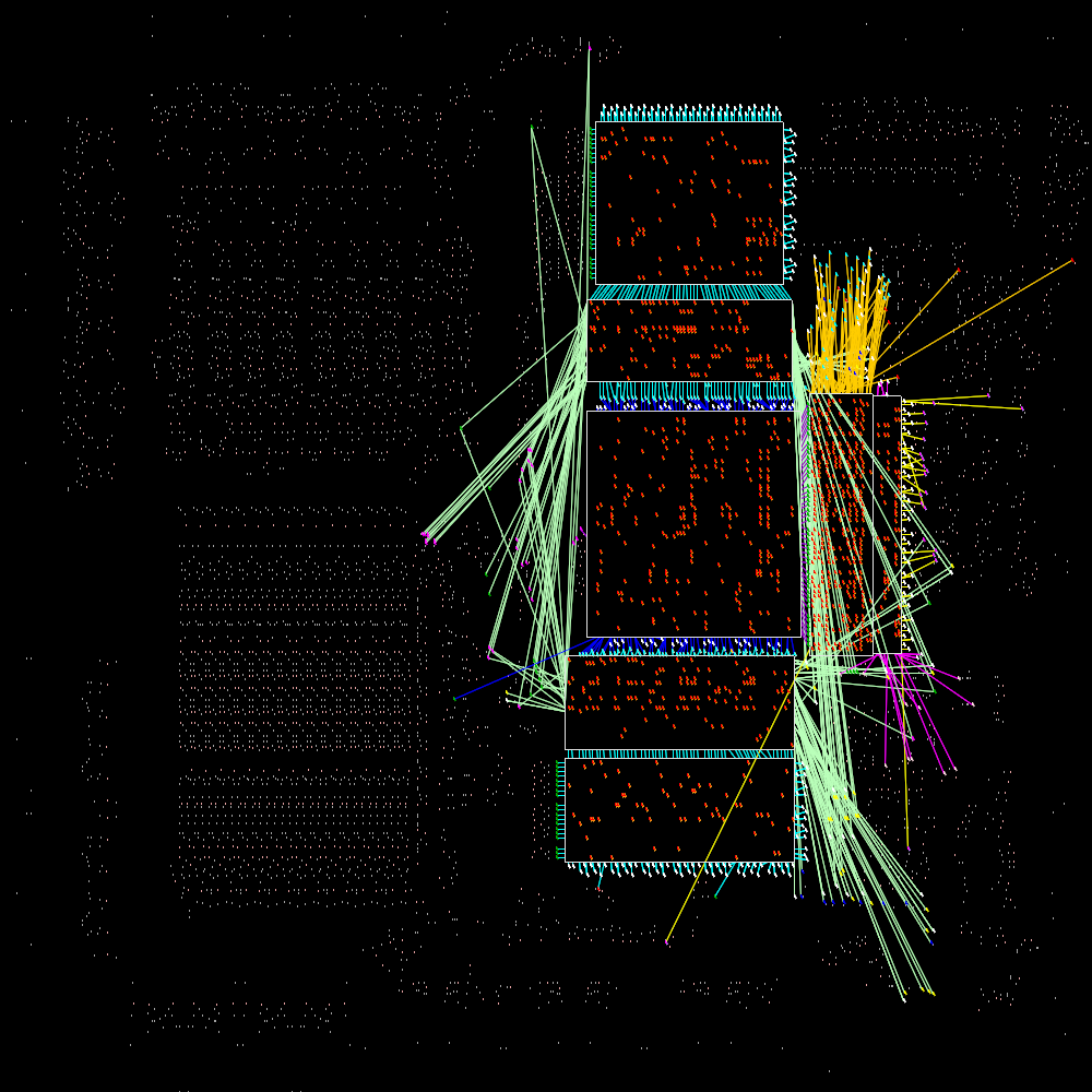
This information is based on the 8085 reverse-engineering done by the visual 6502 team. This team dissolves chips in acid to remove the packaging and then takes many close-up photographs of the die inside. Pavel Zima converted these photographs into mask layer images, generated a transistor net from the layers, and wrote a transistor-level 8085 simulator.

I took the transistor net and used it to figure out how the ALU works. First, I converted the transistor net into gates. Next I figured out which gates are part of the ALU and put them into a schematic. Then I examined how the circuit worked for different operations and eventually figured out how it works.

Conclusion

The ALU of the 8085 is an interesting circuit. At first it seemed like an incomprehensible pile of gates with mysterious control lines, but after some investigation I figured it out. The 8085 ALU is implemented very differently from the 6502's ALU (which I'll write up later). The 6502's ALU uses fairly straightforward circuits to generate the SUM, AND, XOR, OR, and SHIFT values in parallel, and then uses a simple pass-transistor multiplexor to pick the desired operation. This is in contrast to the 8085 ALU, which generates only the desired value.

Notes on the PLA on the 8085 chip

The 8085 processor uses a PLA (programmable logic array) to control much of the activity within the processor, such as instruction decoding and controlling the data flow between components of the chip. Pavel Zima has reverse-engineered the transistor-level circuitry of the 8085 microprocessor. I've looked into this in a bit more to figure out the architecture of the Programmable Logic Array, which takes up a large fraction of the chip. The PLA circuit is much more complex than the PLA on the 6502, for instance. It turns out that Pavel is ahead of me with information on the decode and timing PLAs, but the information below may still be of interest.

The following diagram shows the arrangement of the PLA on the chip (image from Visual 6502). The PLA has 5 planes, which I have labeled A through G.

The block diagram below shows approximately how the planes are connected. Plane A receives inputs from the instruction circuit. Its outputs are fed into the small plane B, producing outputs that go into the instruction circuit. The outputs from A also are fed into C (through pass transistors).

Planes D and E can be considered the same plane, split apart for better layout. They share 11 input lines, and the remaining inputs are different between D and E. These inputs come from the ALU/register circuits on the left, as well as other parts of the chip. They also receive inputs from G - these inputs are not handled via normal PLA input lines, but are wired through transistors directly to the associated output lines, which makes the layout more compact.

Planes F and G provide outputs through pass transistors to the ALU/register circuits. These outputs probably control the actions and bus activity, but more analysis is needed.

The following diagram shows how the PLA planes are wired to the rest of the chip. Planes D and E in particular receive inputs from many parts of the chip. The outputs from F and G are very short because the displayed wires end at the nearby pass transistors to the left.

The transistors in the PLA

I have diagrams showing where the transistors are in each PLA grid here.

The 6502 CPU's overflow flag explained at the silicon level

In this article, I show how overflow is computed in the 6502 microprocessor at the transistor and silicon level. I've discussed the mathematics of the 6502 overflow flag earlier and thought it would be interesting to look at the actual chip-level implementation. Even though the overflow flag is a slightly obscure feature, its circuit is simple enough that it can be explained at the silicon level.

The 6502 microprocessor chip

The 6502 is an 8-bit microprocessor that was very popular in the 1970s and 1980s, powering popular home computers such as the Apple II, Commodore PET, and Atari 400/800. The following photograph shows the die of a 6502 processor. Looking at the photograph, it seems impossibly complex, but it turns out that it actually can be understood, using the Visual 6502 group's reverse engineered 6502. The red box shows that part of the chip that will be explained in this article. The 6502 chip is made up of 4528 transistors (3510 enhancement transistors and 1018 depletion pullup transistors). (By comparison, a modern Xeon processor has over 2.5 billion transistors, which would be almost hopeless to try to understand.)

Photomicrograph of the 6502. The following diagrams zoom in on the red box, where the overflow circuit is located.

Photomicrograph of the 6502, from Visual 6502 (CC BY-NC-SA 3.0). The following diagrams zoom in on the red box, where the overflow circuit is located.

As a rough overview of the above photograph, the edge of the die shows the wires going to the pins. Approximately top fifth of the chip (with the regular rectangular pattern) is the PLA that decodes instructions. The middle third is a bunch of logic, mostly to do additional decoding of instructions. The bottom half has the registers, ALU (arithmetic-logic unit), and main busses. They are all 8 bits, with each bit in a horizontal layer. The high-order bit is at the bottom of the photo, and this is where the overflow logic lies.

The overflow formula

In brief, if an unsigned addition doesn't fit in a byte, the carry flag is set. But if a signed addition doesn't fit in a byte, the overflow flag is set. The 6502 processor computes the overflow bit for addition from the top bits of the two operands (A7 and B7), and the carry out of bit 6 into bit 7 (C6):

V = not (((A7 NOR B7) and C6) NOR ((A7 NAND B7) NOR C6))

For a more detailed explanation of what overflow means, see my previous article or The overflow flag explained.

Gate-level implementation

The overflow computation circuit in the 6502 microprocessor.

Described as gates, the actual circuit to generate the overflow flag in the 6502 turns out to be surprisingly simple. It uses the carry out of bit 6, and the top bits of the two arguments A and B. Since the values of NAND(a7, b7) and NOR(a7, b7) are already available in the ALU (Arithmetic-Logic Unit) for other purposes, the actual overflow circuit is simply the three gates on the right. (The ALU is, of course, much more complex than the part shown above.) This circuit can be seen at the bottom of the 6507 schematic (where the inverted overflow value is called FLOW). You might wonder why the circuit uses NAND and NOR gates so heavily; it turns out that these are much easier to implement with transistors than AND and OR gates.

Transistor-level implementation

The transistors that implement the overflow circuit in the 6502 microprocessor. The circuits on the left compute the NAND and NOR of the top bits of A and B. The circuit on the right computes the overflow flag.
The transistors that implement the overflow circuit in the 6502 microprocessor. The circuits on the left compute the NAND and NOR of the top bits of A and B. The circuit on the right computes the overflow flag. Based on the remarkable transistor-level schematic of the full 6502 chip, reverse-engineered by Balazs.

The circuit above shows the actual implementation of the overflow circuit in the 6502 using NMOS transistors. The circuit to generate the overflow flag is very simple, requiring just a few transistors to implement the three gates. A, B, and carry are the inputs, and the output #overflow indicates complement of the overflow signal.

MOS transistors are fairly easy to understand, since they operate like switches. Most of the transistors are NMOS enhancement mode transistors, which can be considered as switches that close if the gate has a positive input, and are open otherwise. The transistors with a black bar are NMOS depletion mode transistors, which can be considered as pull-up resistors, giving a positive output if nothing else pulls the output low.

The three transistors on the left implement a simple logic gate to compute NAND of A and B. If both inputs A and B are positive, the switches close and connect the output to ground (the horizontal line at the bottom). Otherwise, the pullup transistor connects the output to the positive voltage (circle at the top). Thus, the output is the NAND of A and B - 0 if both inputs are positive, and 1 otherwise.

The next three transistors compute NOR of A and B. If A, B, or both are positive, the associated transistor is switched on and connects the output to ground. Otherwise the output is positive.

The remaining transistors are the actual overflow circuit. The next group of three transistors is a NOR gate, which was described above. It computes the NOR of the carry and the NAND output from the ALU, feeding its output into the final group of four transistors. The four transistors on the right implement an AND gate and NOR gate in a single circuit. If the output from the previous circuit is 1, the rightmost transistor switches on, pulling the output (inverted V) to ground. If both NOR7 and CARRY6 are 1, the two associated transistors switch on, pulling the output to ground. Otherwise, the pullup transistor keeps the output high. The result is the complemented overflow value.

Going to the silicon

Now that you've seen how the circuit works at the transistor level, the silicon level can be explained.

We'll begin with an (oversimplified) description of how the chip is constructed. The chip starts with the silicon wafer. Regions are diffused with an element such as boron, yielding conductive n+ diffusion regions. On top of the polysilicon layer is a layer of metal "wires" providing more connections. For our purposes, diffusion regions, polysilicon, and metal can all be consider conductors. In the 6502, the polysilicon connections run roughly vertical, and the metal wires run generally horizontal.

Structure of an NMOS transistor

Structure of an NMOS transistor. The n+ diffusion regions (yellow) separated by undiffused silicon (gray). The gate is formed by an insulating oxide layer (red) with a diffusion line (purple) over it.

To build a transistor, two n+ regions are separated by an undiffused region. A thin insulating oxide layer on top forms the transistor gate, which is wired to a diffusion line. When charge is applied to the gate via the polysilicon line, the two n+ regions can conduct.

The follow picture zooms in on the base silicon layer in the 6502, showing the region in the red outline. The darker gray regions are n+ diffusion areas, which have been doped to be conducting. The white stripes that separate n+ regions are the transistor gates, showing the thin insulating oxide layer that switches on and off conduction between the neighboring n+ regions. The gray squares are vias, which connect to other layers.

The diffusion layer of the 6502, zoomed in on the overflow circuit. The white strips show transistor gates.

The diffusion layer of the 6502, zoomed in on the overflow circuit. The shaded regions are diffusion regions, and the unshaded regions are undiffused silicon. The white strips show transistor gates. From Visual 6502 (CC BY-NC-SA 3.0).

The next picture shows the polysilicon and metal layers that lie on top of the base silicon. This picture is aligned with the previous one, and you may be able to pick out some of the diffusion layer underneath. The whitish vertical stripes are conductive polysilicon. The greenish metallic-looking horizontal stripes are in fact metal, forming conductors. The gray square are vias, which connect different layers. Note that the chip is crammed full of conductors, making it hard at first glance to tell what is going on.

Closeup of the 6502 microprocessor die, showing the overflow circuit.

Closeup of the 6502 microprocessor die, showing the overflow circuit. From Visual 6502 (CC BY-NC-SA 3.0).
The following picture shows approximately how the transistor-level circuit maps onto the silicon. This circuit is the same as the transistor schematic earlier, just drawn to match the actual layout on the chip. The A, B, and CARRY inputs come from other parts of the chip, and the inverted #OVERFLOW output exits on the right to other destinations.

The 6502 overflow circuit at the transistor level, overlaid on the photomicrograph of the die.

The final picture explains exactly what is happening at the silicon level. It labels the different layers that take part in the overflow circuit with different colors. The lowest layer is the diffusion layer in yellow. On top of this is the polysilicon layer in purple. The topmost layer of metal is in green. Power (Vcc) and ground are supplied through the metal layer. The crosshatches show transistor gates, formed by polysilicon over insulating oxide. The skinny crosshatched areas are the enhancement transistors used as switches. The blocky crosshatched areas connected to Vcc (positive voltage) are the depletion transistors used as pullups.

The overflow circuit in the 6502 at the silicon level. The diffusion layer is yellow. Polysilicon is in purple. Metal is in green. Crosshatches show transistors.

The circuit can be understood starting in the upper left. A and B are bit 7 of the A and B values going into the ALU. (A and B come from elsewhere in the processor.) If A and B are positive, the two upper transistors (vertical crosshatches) will pull the NAND output low. If A or B are positive, one of the two transistors below will pull the NOR output low. The NAND and NOR outputs travel to multiple parts of the ALU through metal, polysilicon, and diffusion "wires", but only the relevant connections are shown.

In the lower left is the first gate of the overflow circuit, computing the NOR of the NAND output and carry (which comes from elsewhere in the chip). The polysilicon line (purple) on the bottom is the output from this gate. In the lower right is the second gate of the overflow circuit, combining the NOR, carry, and output of the first gate. The result is #overflow (i.e. inverted overflow).

You can see this circuit in action in the Visual 6502 simulator. The color scheme in the simulator is different - diffusion is green, yellow, orange, and red. The metal layer is shown in ghosted white, but Vcc and ground are omitted. Polysilicon is in purple, and the transistors are not explicitly shown.

Conclusions

By focusing on a simple circuit, the 6502 microprocessor chip can actually be understood at the silicon level. It's interesting to see how the complex patterns etched on the chip can be mapped onto gates, and their function understood.
More comments on this article are at Hacker News. Thanks for visiting!

The 6502 overflow flag explained mathematically

The overflow flag on the 6502 processor is a source of myth and confusion. In this article, I explain signed and unsigned binary arithmetic, discuss the meaning of the overflow flag, show various formulas for computing overflow, and dispell some myths about the overflow flag.

You might be looking for my other article on overflow - The 6502 CPU's overflow flag explained at the silicon level - which is much more popular.

The 6502 is an 8-bit microprocessor that was very popular in the 1970s and 1980s, powering popular home computers such as the Apple II, Commodore PET, and Atari 400/800. The 6502 instruction set includes 8-bit addition and subtraction operations. Various status flags (carry, zero, negative, overflow) are set based on the result of the operation. Most of the flags (carry, zero, negative) are straightforward, but the meaning of the overflow (V) flag is harder to understand. If the result of a signed add or subtract won't fit into 8 bits, the overflow flag is set. (The overflag is affected in a couple other cases - the BIT operation, and the SO pin on the chip. These are discussed in detail in the excellent article The overflow flag explained, so I won't discuss them here.)

Addition on the 6502

The 6502 has an 8-bit addition operation ADC (add with carry) which adds two numbers and a carry-in bit, yielding an 8-bit result and a carry out bit. The following diagram shows an example addition in binary, decimal, and hexadecimal.

Unsigned binary addition of 80 + 44 yielding 224.

The carry flag is used as the carry-in for the operation, and the resulting carry-out value is stored in the carry flag. The carry flag can be used to chain together multiple ADC operations to perform multi-byte addition.

Ones-complement and twos-complement

The concepts of ones-complement and twos-complement are important to understand signed arithmetic. The ones complement of a number simply flips all 8 bits in the number. That is, the ones complement of N is 255-N. This is very easy to do in hardware.

The twos complement of a number is the ones complement of the number plus 1. That is, the twos complement of N is 256-N. The twos complement is very useful because adding M and the twos complement of N is the same as subtracting N from M. For example, to compute 80 - 112, simply take the twos complement of 112 (binary 10010000) and add it to 80 (binary 01010000), yielding (binary 11100000). This result is the twos complement of 32, indicating -32.

Signed binary addition of 80 and -112 yielding -32.

Note that 80+144 and 80-112 had exactly the same bit-level operations - only the interpretation of the bits was different. This is why twos complement numbers are so useful - the same addition circuit works with them.

To see why twos complement numbers work this way, consider M + (-N) or M - N

M - N
→ M - N + 256Adding 256 doesn't change the 8-bit value.
= M + (256 - N)Simple algebra.
= M + twos complement of NDefinition of twos complement.

Thus, adding the twos complement is the same as subtracting. (With the exception of the carry bit, which is affected by the extra 256. This will be discussed later)

Twos-complement signed numbers

Twos complement numbers are very useful for representing signed numbers, since a number between -128 and +127 can fit into one byte: the top bit is 0 for a normal non-negative number (0 to 127), and the top bit is 1 for a twos-complement negative number (-1 to -128). (The value of the top bit is reflected in the N (negative) status flag.)

The nice thing about signed numbers is that regular binary arithmetic yields the expected results (in most cases). That is, the processor adds or subtracts the numbers as if they are unsigned binary numbers, and the right answer occurs just by interpreting them as signed.

Another example shows that the carry is ignored with signed addition. In this case, 80 and -48 are added, yielding 32. Since 80 + (256-48) = 256 + (80-48), the "extra" 256 ends up in the carry bit.

Signed addition of 80 and -48 yields a carry, which is discarded.

Unfortunately, problems can happen. For instance, 80 + 80 = 160 with unsigned arithmetic, but with signed arithmetic the result is unexpectedly -96. The problem is that 160 will fit into a byte as an unsigned number, but it is too big to store in a byte as a signed number. Since the top bit is set, it is interpreted as a negative number. To indicate this problem, the 6502 sets the overflow flag.

Signed addition of 80 + 80 yields overflow.

The table that explains everything about overflow

The definition of the 6502 overflow flag is that it is set if the result of a signed addition or subtraction doesn't fit into a signed byte. That is, overflow occurs if the result is > 127 or < -128. The symptom of this is adding two positive numbers and getting a negative result or adding two negative numbers and getting a positive result.

This section explores all the possible ways that overflow can occur. The following examples consider the addition of two signed numbers M and N. It is only necessary to consider the top bits of the numbers and the carry from bit 6, as shown in the diagram below, since the lower bits don't affect overflow (except by causing a carry from bit 6).

Binary addition, demonstrating the bits that affect the 6502 overflow flag.

There are 8 possibilities for these bits, as expressed in the table below. For each set of input bits, the table shows the carry out (C7), the top bit of the sum (S7), which is the sign bit, and the overflow bit V. This covers the 4 possibilities for sign of the arguments (positive + positive, positive + negative, negative + positive, negative + negative), with and without carry from bit 6. The table shows an example sum for each line, first expressed in hexadecimal, and then interpreted as unsigned addition and signed addition.

InputsOutputsExample
M7 N7 C6 C7 S7 VCarry / OverflowHexUnsignedSigned
000000No unsigned carry or signed overflow0x50+0x10=0x6080+16=9680+16=96
001011No unsigned carry but signed overflow0x50+0x50=0xa080+80=16080+80=-96
010010No unsigned carry or signed overflow0x50+0x90=0xe080+144=22480+-112=-32
011100Unsigned carry, but no signed overflow0x50+0xd0=0x12080+208=28880+-48=32
100010No unsigned carry or signed overflow0xd0+0x10=0xe0208+16=224-48+16=-32
101100Unsigned carry but no signed overflow0xd0+0x50=0x120208+80=288-48+80=32
110101Unsigned carry and signed overflow0xd0+0x90=0x160208+144=352-48+-112=96
111110Unsigned carry, but no signed overflow0xd0+0xd0=0x1a0208+208=416-48+-48=-96

A few interesting things can be noted from this table. Signed overflow (V=1) happens in two of the eight cases - when the result of adding two positive numbers overflows and ends up negative, and when the result of adding two negative numbers overflows and ends up positive. These rows are highlighted. Signed overflow will never happen when adding a positive number and a negative number, since the result will have a smaller magnitude. Unsigned carry (red in the unsigned column) happens in four of the eight cases, and is independent of signed overflow.

Formulas for the overflow flag

There are several different formulas that can be used to compute the overflow bit. By checking the eight cases in the above table, these formulas can easily be verified.

A common definition of overflow is V = C6 xor C7. That is, overflow happens if the carry into bit 7 is different from the carry out.

A second formula simply expresses the two lines that cause overflow: if the sign bits (M7 and N7) are 0 and the carry in is 1, or the sign bits are 1 and the carry in is 0:
V = (!M7&!N7&C6) | (M7&N7&!C6)

The above formula can be manipulated with De Morgan's laws to yield the formula that is actually implemented in the 6502 hardware:
V = not (((m7 nor n7) and c6) nor ((M7 nand N7) nor c6))

Overflow can be computed simply in C++ from the inputs and the result. Overflow occurs if (M^result)&(N^result)&0x80 is nonzero. That is, if the sign of both inputs is different from the sign of the result. (Anding with 0x80 extracts just the sign bit from the result.) Another C++ formula is !((M^N) & 0x80) && ((M^result) & 0x80). This means there is overflow if the inputs do not have different signs and the input sign is different from the output sign (link).

Subtraction on the 6502

The behavior of the overflow flag is fundamentally the same for subtraction, indicating that the result doesn't fit into the signed byte range -128 to 127. The 6502 has a SBC operation (subtract with carry) that subtracts two numbers and also subtracts the borrow bit. If the (unsigned) operation results in a borrow (is negative), then the borrow bit is set. However, there is no explicit borrow flag - instead the complement of the carry flag is used. If the carry flag is 1, then borrow is 0, and if the carry flag is 0, then borrow is 1. This behavior may seem backwards, but note that both for addition and subtraction, if the carry flag is set, the output is one more than if the carry flag is clear.

Defining the borrow bit in this way makes the hardware implementation simple. SBC simply takes the ones complement of the second value and then performs an ADC. To see how this works, consider M minus N minus borrow B.

M - N - BSBC of M and N with borrow B
→ M - N - B + 256Add 256, which doesn't change the 8-bit value.
= M - N - (1-C) + 256Replace B with the inverted carry flag.
= M + (255-N) + CSimple algebra.
= M + (ones complement of N) + C255 - N is the same as flipping the bits.

The following table shows the overflow cases for subtraction. It is similar to the previous table, with the addition of the B column that indicates if a borrow resulted. Unsigned operation resulting in borrow are shown in red, as are signed operations that result in an overflow.

InputsOutputsExample
M7 N7 C6 C7 BS7 VBorrow / OverflowHexUnsignedSigned
0100100Unsigned borrow but no signed overflow0x50-0xf0=0x6080-240=9680--16=96
0110111Unsigned borrow and signed overflow0x50-0xb0=0xa080-176=16080--80=-96
0000110Unsigned borrow but no signed overflow0x50-0x70=0xe080-112=22480-112=-32
0011000No unsigned borrow or signed overflow0x50-0x30=0x12080-48=3280-48=32
1100110Unsigned borrow but no signed overflow0xd0-0xf0=0xe0208-240=224-48--16=-32
1111000No unsigned borrow or signed overflow0xd0-0xb0=0x120208-176=32-48--80=32
1001001No unsigned borrow but signed overflow0xd0-0x70=0x160208-112=96-48-112=96
1011010No unsigned borrow or signed overflow0xd0-0x30=0x1a0208-48=160-48-48=-96

Comparing the above table with the overflow table for addition shows the tables are structurally similar if you take the ones-complement of N into account. As with addition, two of the rows result in overflow. However, some things are reversed compared with addition. Overflow can only occur when subtracting a positive number from a negative number or vice versa. Subtracting positive from positive or negative from negative is guaranteed not to overflow.

The formulas for overflow during addition given earlier all work for subtraction, as long as the second argument (N) is ones-complemented. Since internall subtraction is just addition of the ones-complement, N can simply be replaced by 255-N in the formulas.

Overflow myths

There are a lot of myths and confusion about the overflow flag. Since the flag is a bit difficult to understand, simple but wrong explanations are easy to find.

The most common myth is that just as the carry bit indicates a carry (or overflow) from bit 7, the overflow bit indicates a carry (or overflow) from bit 6 (example, example, example). As can be seen from the table above, sometimes a carry from bit 6 causes an overflow and sometimes it doesn't.

Another myth is that for multi-byte signed numbers, you use the overflow flag instead of the carry flag to carry from one byte to another (example). In fact, carry is still used to add/subtract multi-byte signed numbers, the same as with unsigned numbers.

It is sometimes claimed that the overflow bit is set if a result is too large to be represented in a byte (example, example). This omits the critical word signed - a signed result can be too large to fit in a byte, even if the unsigned result fits, and vice versa. Examples are in the table above.

Another confusing explanation is that the overflow flag is set when the sign bit is affected (example). The table shows that sometimes there is overflow when the sign bit is affected by bit 6 carry, and sometimes there is overflow when the sign bit is not affected.

Conclusions

This is probably more than anyone really wants to know about the overflow flag. In my next article, I discuss how overflow is implemented at the silicon level.

JavaScript on the go: Programming from your phone

Have you ever wanted to write a program when the only computer available is your phone? You can use an Android phone to write and run JavaScript programs by using a few simple tricks.

While traveling over Thanksgiving I was thinking about how the 6502 microprocessor works and wanted to analyze some Boolean logic circuits. A trivial programming task but the only computer I had was my phone.

I searched for programming languages available on Android. Python for Android looked way too complex. The Clojure REPL intrigued me but I didn't want to learn Clojure right now. Other languages seemed limited or buggy. Then I was struck by the obvious choice for a powerful and fully-supported language with graphics capabilities: JavaScript. I could run JavaScript programs in the browser if I had a way to enter them.

I downloaded DroidEdit Pro which gave me a fullscreen editor for files on my phone. Typing HTML on the phone was painful until I downloaded the Hacker's Keyboard, which makes it much easier to type special characters. The picture below shows these tools in use.

My development cycle is:

  • Edit the code in DroidEdit and save it to a local .html file.
  • Select 'Preview in Browser' from DroidEdit and test the program.
  • Upload the file to my web server using DroidEdit's SFTP support when ready.

For debugging, the trick is to use the default browser, not Chrome. Enter about:debug in the URL bar to open the JavaScript console, which is vital for debugging.

Obviously this environment isn't as powerful as a full-size keyboard and monitor and powerful editor, but it lets me program no matter where I am. I haven't got the hang of cut-and-paste in the editor, but shift-arrow seems to work better than tapping.

Here's my program in action. It wont get any style points - I rapidly lost my enthusiasm for whitespace with the tiny keyboard - but it got the job done.

I also used this development environment to show my nephew how to make web pages with HTML. He thought it was very cool that he could type HTML into the phone, hit Control-S to save, and immediately load the web page on his iPad. He's now busily learning HTML and building his own web pages.

I hope these tips help you program while on the road. Leave a comment if you have tips of your own.

Teardown of the mysterious KMS 4-port USB charger

In this article I tear down a 4-port USB charger of puzzling origin. This charger is a huge step above the $2 counterfeit chargers I examined earlier in design and manufacture, but considerably below the quality of name-brand chargers. Likewise with safety - the charger was built with some attention to safety, but appears to fall short of UL standards.

The circuit inside the KMS charger is a straightforward  flyback switching power supply. This photo shows the key components.

One puzzle about this charger is it's unclear who makes it and what model it is. The case says it's the KMS AC-09 but the circuit board says "TC09-new-V4.2". Amazon lists the brand as "Cosmos®", but I couldn't find any sign that KMS or Cosmos are actual companies. After some web searches, I think the charger is built by Guangzhou Panyu Qiaonan Saidi Electronic Factory (more) as the TC09 charger for $5.30 wholesale, or maybe HK Yingjia International, a consumer electronics manufacturer in Shenzhen (more). In any case, I'll call this the "KMS charger" since I need to call it something.

In my previous lab analysis of 12 chargers, I compared a dozen different chargers in 9 different categories, rating them from 1 to 5 'bolts' and the KMS charger came in about average in terms of performance. The results for the KMS charger are summarized below. For details on these measurements, see my previous article A dozen USB chargers in the lab).

Overall rating 3 out of 5
Vampire (idle) power usage 3 out of 5
Efficiency under load 3 out of 5
Achieves power rating 5 out of 5
Spikes in output 1 out of 5
High-frequency noise in output 4 out of 5
Ripple in output 5 out of 5
Voltage sag 1 out of 5
Current sag 1 out of 5
Regulation quality 1 out of 5

The good and the bad

Overall, this charger is much higher quality than the $2 counterfeit chargers, but considerably lower quality than name-brand chargers.

The charger provides more filtering than basic chargers, from the large input choke to the multiple output inductors. It includes X and Y capacitors for filtering.

The charger looks mostly safe, although it doesn't have UL certification and I suspect it would fail certification. The 6mm clearance between the primary and secondary looks solid. However, the transformer windings are only separated by 3mm, rather than 6mm, as I show below. (This is still much superior to the $2 chargers that have almost no separation.)

One interesting feature of the power supply is the power plug can be interchanged for use in different countries. (Some other chargers such as the HP TouchPad and Apple iPad are similar.)

The KMS TC-09 (AC09) 4-port USB charger. The power plug can be interchanged for use in different countries.

The charger has some quality issues. The power quality measurements I did in my previous article show the KMS charger has fairly poor quality output, with a lot of noise in the output.

The IC datasheet recommends 200 mm2 of foil on the IC output pins to provide cooling. I measured about 18 mm2 (less than 10% of recommended), which suggests the charger may overheat under full load.

Some of the components in the KMS charger are mounted crooked, rather than flush with the circuit board. The inductor on the right and the optoisolator on the left are two examples.

The above photo shows that the build quality of the charger is not extremely high. The inductor at the front right is very crooked, and the optocoupler at the left is somewhat crooked. While this doesn't affect the performance, it shows the assembly was rapid rather than careful. More concerning, some of the solder joints appear to be almost bridged, which could cause catastrophic failure of the charger. I also found a government report of a KMS charger catching fire, apparently due to a loose wire in the power plug.

One unique feature of the charger is the blue LEDs which cause it to emit an eerie blue glow when in use. A lot of users dislike this though (according to reviews), because the light is distracting at night.

The KMS 4-port USB charger emits an eerie blue glow when in use.

The circuit

Annotated schematic of the KMS TC-09 USB charger.

For readers interested in circuits, I have prepared the above approximate schematic (click for a larger view). The circuit is pretty straightforward compared to other chargers (look at my iPhone charger schematic for comparison). Starting at the upper left, the input AC is converted to DC by the diode bridge, and then filtered by a simple inductor-capacitor filter. This high-voltage DC is connected to the flyback transformer primary. The THX203H control IC switches the other side of the flyback transformer to ground through the current-sense resistors R12A and R12B and inductor L3. (Most chargers use a separate switching transistor, but in this charger, the transistor is inside the control IC.) The snubber circuit R2, C3, and D6 absorbs some of the high-frequency switching spikes (although looking at the output below, this circuit isn't entirely successful). The auxiliary transformer winding and D7 and C4 provide the DC power to the control IC. The optocoupler provides feedback to the IC, indicating the output voltage level.

On the secondary side, the high-speed Schottky diodes (D5) convert the transformer output to DC. This is then filtered through an inductor-capacitor filter that smooths it out. The output voltage feedback is generated by the TL431A regulator and fed into the optocoupler.[1]

Finally, the actual USB output circuitry has more components than you'd expect. For each pair of ports, four resistors set the D+ and D- voltages to indicate to devices that the charger is (pretending to be) an Apple 2A charger. Each port has a small bypass capacitor to smooth out power transients. Finally there are two blue LEDs with current-limiting resistors to provide the blue glow.

The controller IC poses a bit of a mystery. It's labeled as the THX 203H controller, which turns out to be manufactured by NanJing TongHuaXin Electronic Co, Ltd., a Chinese switching power supply chip company (details). The datasheet for this part is very hard to understand, as it is machine-translated from Chinese, for example:

The startup circuit inside IC is designed as a particular current inhalation way, so it can start up with the magnification function of the power switch tube itself.
After some more investigation, this chip seems to be the SDC603 Current Mode PWM Controller designed by SDC Semi (Shaoxing Devechip Microelectronics Co., Ltd.). This is a Chinese state-level R&D center that is part of China's Torch Plan Project to develop high-tech industries. (Also check out the SDC company song.)

The controller chip is a basic 8-pin current-mode PWM controller chip. It includes a built-in NPN power transistor, which reduces the charger part count. The chip can produce 12 watts output power.

Circuit board

The circuit board from the KMS-AC09 charger on the left and a circuit board from the HP TouchPad charger on the right. Note the much higher density of the TouchPad board.

The above picture shows the KMS charger circuit board on the left and a circuit board from the HP TouchPad charger on the right. Compact phone chargers such as the iPhone or TouchPad chargers go to amazing effort to pack the components as tightly as possible. The KMS charger on the other hand has a much more spacious design with a lot of wasted space. Since any charger with 4 USB ports is going to be fairly large, they probably figured it's not worth the effort to make the rest of the circuitry compact. The difference in density between the two circuit boards is striking, though.

A key safety feature of the KMS charger is visible in the middle of the circuit board - note the angular cut-out slot, and the empty vertical region with no circuitry. This isolates the high-voltage circuits on the right from the low-voltage output circuits on the left. The KMS charger has a safe 6mm gap and the cut-out provides additional creepage distance. Counterfeit chargers usually skip this critical safety feature, with only a millimeter or two keeping the high voltage from reaching the output and shocking the user.

You might wonder how the charger works if the high voltage and low voltage circuits are separated by a gap. The key is that any components that cross this gap must be specially designed to avoid electrical hazards. The key component is the flyback transformer, which transfers the power through magnetic fields, avoiding any direct electrical connection between the two sides. The feedback signal passes from the secondary to the primary through an optocoupler, which transmits the feedback through a light signal, again avoiding an electrical connection. Finally, a Y safety capacitor connects the primary and secondary grounds to reduce electrical noise. The design of a Y capacitor ensures it won't pass dangerous electrical currents, and won't short out even under fault conditions.

Transformer teardown

The flyback transformer is the key component of a charger and usually the largest and most expensive. The transformer is where the high input voltage is converted to the output voltage, and the two voltages are in extremely close proximity, so the safety of the transformer is critical. From the outside, you can't tell if the manufacturer saved a few cents by leaving out most of the insulation, as happens with $2 chargers. I tore apart the transformer of the KMS charger to see what's inside.

The black circle on top of the transformer seen earlier is simply a foam disk, which helps reduce transformer noise by padding the transformer against the case. If a charger makes a high-pitched noise, it's usually coming from the transformer. Power supplies are usually designed with switching frequencies higher than people can hear, but in some circumstances it's still audible, especially if you are young and haven't lost high frequency hearing.

A copper 'belly band' provides a shield around the flyback transformer.

Under the first layers of insulating tape is a copper 'belly band' which surrounds the transformer to provide noise shielding from eddy currents in the transformer.[2] This copper shielding is omitted from super-cheap transformers, showing that this charger goes beyond the minimum.

The first winding in the flyback transformer powers the internal circuits of the charger

The windings are all separated by insulating tape. Under the belly band and insulating tape is the auxiliary winding, which provides power to the control IC. You might wonder why the IC needs a separate power supply instead of using the USB power output, but this wouldn't be safe because the USB output would no longer be isolated from the input. This winding is 9 turns of wire; since the IC requires low current, the wire is fairly thin.

The first half of the primary winding in the flyback transformer. Note the 3mm white boundary tape at the right that keeps the winding away from the edge.

Above you can see half of the primary winding, which is fed by the input power. This winding has 40 turns of wire.

An interesting safety feature is the 3 mm "margin tape"[3] to the lower right of the winding, which ensures that the primary winding stays 3 mm away from the edge. I was interested to see this, since other transformers I've disassembled use triple-insulated wire instead of boundary tape. To ensure safe electrical isolation between the primary and secondary windings, either the secondary wires need to be triple-insulated, or there needs to be at least 6mm of distance between the windings. Super-small chargers don't have 3mm of extra room, so they use the more expensive triple-insulated wire. But since the KMS is larger, it uses the 3mm margin tape. I'm not an expert on safety requirements, but it looks like this transformer doesn't quite meet the requirements. Normally, the margin tape is put on both sides, so there's a total of 6mm creepage distance between the windings.[4][5] But since the tape is only on one side, the windings only have half of the required distance.

To support high current, the secondary winding in the flyback transformer is four strands of thick wire. Note the 3mm white boundary tape at the right that keeps the winding away from the edge.

The secondary winding provides the low-voltage high-current output with 8 turns of wire. In order to support 2 amps, this winding has thick wire with four strands in parallel. I haven't seen parallel strands like this before, probably because the KMS charger supplies higher power. Note the 3mm margin tape keeping the winding away from the edge.

The second half of the primary winding in the flyback transformer. The 3mm boundary tape is clearly visible at the right.

Finally, the second half of the primary winding forms the innermost layer of the transformer; this is also 40 turns of wire. The primary winding is split into two layers that surround the secondary winding for better electrical properties. Note that the primary winding is 80 turns, while the secondary output winding is 8 turns. To oversimplify a bit, this means the output will be 10 times the current of the input at 1/10 the voltage, which is how the high voltage low current input results in the low voltage high current output. The above picture gives a good view of the 3mm margin tape at the right that keeps the wire away from the edge of the core.

Measuring the charger in use

The charger is a switching power supply using a flyback transformer. How this works is the high voltage DC is switched on and off tens of thousands of times a second by the control IC. These pulses of DC are sent into the flyback transformer. A flyback transformer is different from normal transformers in that the output diode blocks power from flowing out of the transformer while power is flowing in. Instead, as the current increases, power is stored in the transformer as a magnetic field. When the input current switches off, the stored power then flows out of the transformer, providing the desired output.

By looking at the output voltage and frequency spectrum, we can determine a fair bit about how the device operates. I measured a constant 60 kHz switching frequency above 1 amp output load, but a dropping frequency for lower loads. The datasheet gives some clues to this behavior. The power supply normally operates using PWM (pulse width modulation). The switching frequency is constant, but the amount of time the power transistor is on varies. The longer it is on, the more power into the transformer and the more output power. This matches the observed behavior from 1 amp to 3.5 amps. The datasheet also describes how the switching frequency drops under low power, which matches what I observed below 1 amp.

KMS charger output (yellow)and spectrum (orange) at 2A.  Note the spectrum peaks at 60.1 kHz and harmonics.

The above oscilloscope trace illustrates the behavior when producing 2 amps. The frequency spectrum shows narrow peaks (orange) at the 60 kHz switching frequency and harmonics. The yellow output voltage shows a bunch of large spikes due to the power switching on and off - this indicates that the charger isn't filtering the output very well, letting these spikes get into the connected device.

The diagram below zooms in to show the output in more detail. Each spike is when the switching transistor turns on at 60 kHz. The output power drops as the current through the flyback transformer increases (since the transformer secondary is blocked by the diode at this time). The output then climbs when the transistor switches off and the power is transferred to the secondary.

KMS charger output at 2A, showing the effect of the switching frequency.

As the charger load increases above 3 amps, the quality of the output significantly decreases, and large 120 Hz ripple appears in the output (yellow). This is probably because the input capacitors can't store enough power to provide a constant output at this high load. Since the charger is only rated to provide 2.1 amps of output, I don't consider this a design flaw, but it's interesting to see this behavior in the output. The key result here is not to overload the charger, because the power quality gets much worse.

KMS charger output (yellow)and spectrum (orange) at 3A.  The output contains a lot of 120 Hz ripple as well as switching spikes.

The charger is designed to reduce the switching frequency under low load for efficiency. I found this feature kicks in at loads under 1 amp, with the switching frequency smoothly dropping from 60 kHz to 29 kHz at 250 mA load and even lower under no load. The graph below shows the frequency spectrum at 250 mA load. Note that the spikes are wider than the previous case since the frequency becomes more unstable when it is reduced.

The frequency spectrum of the charger under lower (250 mA) load shows the reduced 29 kHz switching frequency and harmonics.

The output waveform below at 250 mA is similar to the previous (2A) case, except at a lower frequency. Note that the output still has large spikes when the transistor switches on. The output voltage drops while the switching transistor is on and then rises while the transistor is off (due to the flyback design), so you can see below that the transistor is off most of the time at low power.

The output waveform of the charger under low (250mA) load shows a lower 29 kHz switching frequency.

Power consumption

Measuring the power consumption of a charger is tricky because the charger doesn't use power like a normal resistive load, but uses a nonlinear part of the input current. This results in a power factor lower than unity. (You might expect that the poor power factor is because the charger switches on and off thousands of times a second, but actually it's the fault of the diode bridge.) I measured the power consumption of the charger under load by measuring the instantaneous line voltage and current, computing the instantaneous power, and then computing the real power from this.[6] In the following diagrams, the input line voltage is shown in yellow, and the input current is in cyan. The instantaneous power is graphed in orange at the bottom - simply the product of the voltage and current.[7]

The oscilloscope output below shows the power usage of the charger under no load. The line input voltage (yellow) is a nice sine wave, but the current (cyan) is very irregular. There is a bump corresponding to the voltage peaks as the input diodes conduct and re-charge the filter capacitors. The remaining current oscillations are unusual - I haven't seen them in other chargers, and I expect they are due to the large input choke. From the orange line you can see that the power usage has small spikes at 120 Hz. Taking the power factor into account and computing real power shows the charger uses 180 mW when idle which is fairly high, but actually lower than the Apple iPhone charger.

KMS charger line input under no load. Yellow is 120V input, cyan is input current. Bottom shows instantaneous power.

With load applied to the charger, the power usage shoots up as shown below. I compute the power usage as 6.4 watts, while the charger is supplying 4.4 watts to the output, for an efficiency of 69%. The shape of the current curve (cyan) and power curve (orange) shows that the charger is taking line power about half the time (the big curved peaks), and not for the other half (the flat oscillations in between). This illustrates the bad power factor that switching power supplies have. (PC power supplies often use power factor correction (PFC) circuits to improve the power factor.)The yellow input voltage curve is somewhat distorted, probably due to the lame isolation transformer I used.

KMS charger line input under load. Yellow is 120V input, cyan is input current.

You might wonder what happens if you short-circuit the output of the charger. It is designed to shut down before damage occurs, rather than self-destruct. After the internal voltage drops, the charger will start up again, and repeat this cycle until the problem goes away. This is called "hiccup mode", since the charger generates hiccups of power. The oscilloscope trace below shows the power consumption of the KMS charger when shorted. Note the pulses as it start up and shuts down every 250 milliseconds.

KMS charger line input under shorted load. Yellow is 120V input, cyan is input current. Bottom shows instantaneous power. Note the 'hiccup' shutdown and restart every 250 milliseconds.

Components

For those who are interested in the components, I have some details. The two 6.8uF 400V electrolytic capacitors in the primary are made by ChengX. The two 470uF capacitors in the secondary are made by JWCO. The X capacitor is a .1uF K 275V X2 made by Dain Electronics, a Chinese manufacturer of plastic metal film capacitors, now merged with WINDAY Electronic Industrial Co Ltd. The Y1 capacitor is a JN222M 2200pF disk ceramic suppression capacitor manufactured by Jya-Nay, a Taiwanese capacitor company. There's also a blue 681J (i.e. .68nF) polyester film capacitor of unknown manufacturer; looking at the circuit board this capacitor (C7) was originally a surface-mounted device, but was replaced with a larger capacitor.

The diodes are manufactured by MIC (Master Instrument Corporation, Shanghai). Most chargers use a diode bridge to convert the AC to DC, but this charger uses four independent diodes, which are 1N4007 700V diodes. The secondary rectification uses two Schottky diodes (SR360 3 amp 60V) from MIC. The circuit board uses the unusual mounting of two diodes on top of each other soldered into the same holes. The charger also uses FR107 700V fast recovery diodes.

Like most power supplies, the charger uses a TL431A for the voltage feedback.[1] This TL431A is produced by Wing Shing Computer Components The optocoupler is an ORPC 817B optocoupler from Shenzen Orient Technology Co., Ltd. (I don't want to speculate on the cultural significance of their raising the flag over Iwo Jima company logo.)

Conclusion

The KMS charger occupies an interesting middle ground between dangerous $2 counterfeit chargers and expensive name-brand chargers. Tearing down this 4-port USB charger of unknown origin reveals details of the circuitry. It also illustrates a network of Chinese suppliers and manufacturers, most of which are hardly known in the US. On Amazon, customer ratings for this charger are split between people who love it and people who hate it, which seems reasonable given what I saw in the teardown. Thanks to Gary F. for providing the charger.

Notes and references

[1] To summarize the feedback circuit: R17 and R18 form a resistor divider on the output voltage. If the output voltage is above 5.125 volts, the TL431 control input will be above 2.5 and the TL431 conducts. This energizes the optocoupler, providing current pulling the FB pin lower. Low FB increases the duty cycle, increasing the maximum transformer current, and increasing the output voltage. If the output voltage is considerably too high, or overtemperature is sensed, the switching frequency is decreased, reducing the power transferred to the output. (This is over-simplified; the frequency response of the feedback control loop is controlled via R13, R16, C8, and C9.) An alternative is to sense voltage from the primary side, so the feedback circuit can be eliminated. This reduces the total charger cost by about 20 cents according to a report.

[2] The use of a copper "belly band" in flyback transformers is discussed in Flyback Transformer Design for the UCC28600 (page 2). It provides an electromagnetic radiation shield. The article mentions that the belly band may cause difficulties with creepage requirements and that seems to be the case with the KMS, since there is only 3mm creepage between the primary-grounded belly band and the secondary wiring.

[3] A lot of interesting information about flyback transformer design and construction is in Cookbook for do-it-yourself transformer design

[4] A discussion of how to achieve 5-6mm creepage distance by using 2.5 or 3mm margin tape is in Flyback Transformer Design for the IRIS40xx Series. Note that the margin tape must be on both sides of the winding to achieve this distance, while the KMS transformer only uses the tape on one side.

[5] Safety Considerations in Power Supply Design provides a detailed explanation of safety requirements for power supplies. It explains creepage and clearance

[6] See Understanding power factor and input current harmonics in switched mode power supplies for details on power factor, power supplies have poor power factors, and why poor power factors are a bad thing. Briefly, the power factor is due to the non-linear current through the diodes at peaks, not due to a phase shift. Real power can be measured with an oscilloscope as the average value of the instantaneous power, see Power - Real And Apparent: A Tutorial On Basic Line Power Measurements or Measuring power using the DL750.

[7] For the input power measurements it is very important to use an isolation transformer to avoid destroying your oscilloscope or shocking yourself. For my measurements, a resistor voltage divider reduced the input line voltage - the actual voltage is 11.06 times the displayed probe 1 voltage (C1, yellow). The current was measured through a 5.2 ohm shunt resistor, so the current is 1/5.2 times the displayed probe 2 voltage (C2, cyan). Combining these, the power in watts is 2.13 times the measured C1*C2 value (M1, orange).