Solving edge-match puzzles with Arc and backtracking

I recently saw a tricky nine piece puzzle and wondered if I could use Arc to solve it. It turned out to be straightforward to solve using standard backtracking methods. This article describes how to solve the puzzle using the Arc language.

A edge-matching puzzle. 
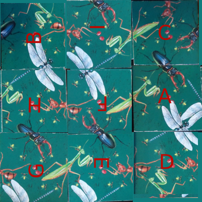
The puzzle consists of nine square titles. The tiles must be placed so the pictures match up where two tiles meet. As the picture says, "Easy to play, but hard to solve." It turns out that this type of puzzle is called an edge-matching puzzle, and is NP-complete in general. For dozens of examples of these puzzles, see Rob's Puzzle Page.

Backtracking is a standard AI technique to find a solution to a problem step by step. If you reach a point where a solution is impossible, you backtrack a step and try the next possibility. Eventually, you will find all possible solutions. Backtracking is more efficient than brute-force testing of all possible solutions because you abandon unfruitful paths quickly.

To solve the puzzle by backtracking, we put down the first tile in the upper left. We then try a second tile in the upper middle. If it matches, we put it there. Then we try a third tile in the upper right. If it matches, we put it there. The process continues until a tile doesn't match, and then the algorithm backtracks. For instance, if the third tile doesn't match, we try a different third tile and continue. Eventually, after trying all possible third tiles, we backtrack and try a different second tile. And after trying all possible second tiles, we'll backtrack and try a new first tile. Thus, the algorithm will reach all possible solutions, but avoids investigating arrangements that can't possibly work.

The implementation

I represent each tile with four numbers indicating the pictures on each side. I give a praying mantis the number 1, a beetle 2, a dragonfly 3, and an ant 4. For the tail of the insect, I give it a negative value. Each tile is then a list of (top left right bottom). For instance, the upper-left tile is (2 1 -3 3). With this representation, tiles match if the value on one edge is the negative of the value on the other edge. I can then implement the list of tiles:
(with (mantis 1 beetle 2 dragonfly 3 ant 4)
  (= tiles (list
    (list beetle mantis (- dragonfly) dragonfly)
    (list (- beetle) dragonfly mantis (- ant))
    (list ant (- mantis) beetle (- beetle))
    (list (- dragonfly) (- ant) ant mantis)
    (list ant (- beetle) (- dragonfly) mantis)
    (list beetle (- mantis) (- ant) dragonfly)
    (list (- ant) (- dragonfly) beetle (- mantis))
    (list (- beetle) ant mantis (- dragonfly))
    (list mantis beetle (- dragonfly) ant))))
Next, I create some helper functions to access the edges of a tile, convert the integer to a string, and to prettyprint the tiles.
;; Return top/left/right/bottom entries of a tile
(def top (l) (l 0))
(def left (l) (l 1))
(def right (l) (l 2))
(def bottom (l) (l 3))

;; Convert an integer tile value to a displayable value
(def label (val)
  ((list "-ant" "-dgn" "-btl" "-man" "" " man" " btl" " dgn" " ant")
   (+ val 4)))

;; Print the tiles nicely
(def prettyprint (tiles (o w 3) (o h 3))
  (for y 0 (- h 1)
    (for part 0 4
      (for x 0 (- w 1)
        (withs (n (+ x (* y w)) tile (tiles n))
          (if
     (is part 0)
       (pr " ------------- ")
     (is part 1)
       (pr "|    " (label (top tile)) "     |")
     (is part 2)
       (pr "|" (label (left tile)) "    " (label (right tile)) " |")
     (is part 3)
       (pr "|    " (label (bottom tile)) "     |")
     (is part 4)
       (pr " ------------- "))))
      (prn))))
The prettyprint function uses optional arguments for width and height: (o w 3). This sets the width and height to 3 by default but allows it to be modified if desired. The part loop prints each tile row is printed as five lines. Now we can print out the starting tile set and verify that it matches the picture. I'll admit it's not extremely pretty, but it gets the job done:
arc> (prettyprint tiles)
 -------------  -------------  ------------- 
|     btl     ||    -btl     ||     ant     |
| man    -dgn || dgn     man ||-man     btl |
|     dgn     ||    -ant     ||    -btl     |
 -------------  -------------  ------------- 
 -------------  -------------  ------------- 
|    -dgn     ||     ant     ||     btl     |
|-ant     ant ||-btl    -dgn ||-man    -ant |
|     man     ||     man     ||     dgn     |
 -------------  -------------  ------------- 
 -------------  -------------  ------------- 
|    -ant     ||    -btl     ||     man     |
|-dgn     btl || ant     man || btl    -dgn |
|    -man     ||    -dgn     ||     ant     |
 -------------  -------------  ------------- 

Next is the meat of the solver. The first function is matches, which takes a grid of already-positioned tiles and a new tile, and tests if a particular edge of the new tile matches the existing tiles. (The grid is represented simply as a list of the tiles that have been put down so far.) This function is where all the annoying special cases get handled. First, the new tile may be along an edge, so there is nothing to match against. Second, the grid may not be filled in far enough for there to be anything to match against. Finally, if there is a grid tile to match against, and the value there is the negative of the new tile's value, then it matches. One interesting aspect of this function is that functions are passed in to it to select which edges (top/bottom/left/right) to match.

;; Test if one edge of a tile will fit into a grid of placed tiles successfully
;;  grid is the grid of placed tiles as a list of tiles e.g. ((1 3 4 2) nil (-1 2 -1 1) ...)
;;  gridedge is the edge of the grid cell to match (top/bottom/left/right)
;;  gridx is the x coordinate of the grid tile
;;  gridy is the y coordinate of the grid tile
;;  newedge is the edge of the new tile to match (top/bottom/left/right)
;;  newtile is the new tile e.g. (1 2 -1 -3)
;;  w is the width of the grid
;;  h is the height of the grid
(def matches (grid gridedge gridx gridy newedge newtile w h)
  (let n (+ gridx (* gridy w))
    (or
      (< gridx 0) ; nothing to left of tile to match, so matches by default
      (< gridy 0) ; tile is at top of grid, so matches
      (>= gridx w) ; tile is at right of grid, so matches
      (>= gridy h) ; tile is at bottom of grid, so matches
      (>= n (len grid)) ; beyond grid of tiles, so matches
      (no (grid n)) ; no tile placed in the grid at that position
      ; Finally, compare the two edges which should be opposite values
      (is (- (gridedge (grid n))) (newedge newtile)))))
With that method implemented, it's easy to test if a new tile will fit into the grid. We simply test that all four edges match against the existing grid. We don't need to worry about the edges of the puzzle, because the previous method handles them:
;; Test if a tile will fit into a grid of placed tiles successfully
;;   grid is the grid of tiles
;;   newtile is the tile to place into the grid
;;   (x, y) is the position to place the tile
(def is_okay (grid newtile x y w h)
    (and 
      (matches grid right (- x 1) y left newtile w h)
      (matches grid left (+ x 1) y right newtile w h)
      (matches grid top x (+ y 1) bottom newtile w h)
      (matches grid bottom x (- y 1) top newtile w h)))
Now we can implement the actual solver. The functions solve1 and try recursively call each other. solve1 calls try with each candidate tile in each possible orientation. If the tile fits, try updates the grid of placed tiles and calls solve1 to continue solving. Otherwise, the algorithm backtracks and solve1 tries the next possible tile. My main problem was accumulating all the solutions properly; on my first try, the solutions were wrapped in 9 layers of parentheses! One other thing to note is the conversion from a linear (0-8) position to an x/y grid position.

A couple refactorings are left as an exercise to the reader. The code to try all four rotations of the tile is a bit repetitive and could probably be cleaned up. More interesting would be to turn the backtracking solver into a general solver, with the puzzle just one instance of a problem.

;; grid is a list of tiles already placed
;; candidates is a list of tiles yet to be placed
;; nextpos is the next position to place a tile (0 to 8)
;; w and h are the dimensions of the puzzle
(def solve1 (grid candidates nextpos w h)
  (if
    (no candidates)
      (list grid) ; Success!
    (mappend idfn (accum addfn ; Collect results and flatten
      (each candidate candidates
        (addfn (try grid candidate (rem candidate candidates) nextpos w h))
        (addfn (try grid (rotate candidate) (rem candidate candidates) nextpos w h))
        (addfn (try grid (rotate (rotate candidate)) (rem candidate candidates) nextpos w h))
        (addfn (try grid (rotate (rotate (rotate candidate))) (rem candidate candidates) nextpos w h)))))))

; Helper to append elt to list
(def append (lst elt) (join lst (list elt)))

;; Try adding a candidate tile to the grid, and recurse if successful.
;; grid is a list of tiles already placed
;; candidate is the tile we are trying
;; candidates is a list of tiles yet to be placed (excluding candidate)
;; nextpos is the next position to place a tile (0 to 8)
;; w and h are the dimensions of the puzzle
(def try (grid candidate candidates nextpos w h)
  (if (is_okay grid candidate (mod nextpos w) (trunc (/ nextpos w)) w h)
    (solve1 (append grid candidate) candidates (+ nextpos 1) w h)))

The final step is a wrapper function to initialize the grid:

(def solve (tiles (o w 3) (o h 3))
  (solve1 nil tiles 0 w h))

With all these pieces, we can finally solve the problem, and obtain four solutions (just rotations of one solution):

arc> (solve tiles)
(((1 -2 -4 3) (2 4 1 -3) (4 -1 2 -2) (-3 1 4 -2) (3 -4 -1 2) (2 1 -3 3) (2 -4 -1 -3) (-2 1 4 -3) (-3 -4 4 1))
((2 4 -2 -1) (-3 2 3 1) (4 -3 1 -4) (1 2 -3 4) (-1 3 2 -4) (4 -2 -3 1) (-4 1 3 -2) (4 -3 -2 1) (-1 2 -3 -4))
((1 4 -4 -3) (-3 4 1 -2) (-3 -1 -4 2) (3 -3 1 2) (2 -1 -4 3) (-2 4 1 -3) (-2 2 -1 4) (-3 1 4 2) (3 -4 -2 1))
((-4 -3 2 -1) (1 -2 -3 4) (-2 3 1 -4) (1 -3 -2 4) (-4 2 3 -1) (4 -3 2 1) (-4 1 -3 4) (1 3 2 -3) (-1 -2 4 2)))
arc> (prettyprint (that 0))
 -------------  -------------  ------------- 
|     man     ||     btl     ||     ant     |
|-btl    -ant || ant     man ||-man     btl |
|     dgn     ||    -dgn     ||    -btl     |
 -------------  -------------  ------------- 
 -------------  -------------  ------------- 
|    -dgn     ||     dgn     ||     btl     |
| man     ant ||-ant    -man || man    -dgn |
|    -btl     ||     btl     ||     dgn     |
 -------------  -------------  ------------- 
 -------------  -------------  ------------- 
|     btl     ||    -btl     ||    -dgn     |
|-ant    -man || man     ant ||-ant     ant |
|    -dgn     ||    -dgn     ||     man     |
 -------------  -------------  ------------- 
I've used gimp on the original image to display the solution. I've labeled the original tiles A-I so you can see how the solution relates to the original image. Using Arc to display a solution as an image is left as an exercise to the reader :-) But seriously, this is where using a language with extensive libraries would be beneficial, such as Python's PIL imaging library.

solution

Theoretical analysis

I'll take a quick look at the theory of the puzzle. The tiles can be placed in 9! (9 factorial) different locations, and each tile can be oriented 4 ways, for a total of 9! * 4^9 possible arrangements of the tiles, which is about 95 billion combinations. Clearly this puzzle is hard to solve by randomly trying tiles.
arc> (* (apply * (range 1 9)) (expt 4 9))
95126814720

We can do a back of the envelope calculation to see how many solutions we can expect. If you put the tiles down randomly, there are 12 edge constraints that must be satisfied. Since only one of the 8 possibilities matches, the chance of all the edges matching randomly is 1 in 8^12 or 68719476736. Dividing this into the 95 billion possible arrangements yields 1.38 solutions for an arbitrary random puzzle. (If this number were very large, then it would be hard to create a puzzle with only one solution.)

We can test this calculation experimentally by seeing how many solutions there are are for a random puzzle. First we make a function to create a random puzzle, consisting of 9 tiles, each with 4 random values. Then we solve 100 of these:

arc> (def randtiles ()
  (n-of 9 (n-of 4 (rand-elt '(1 2 3 4 -1 -2 -3 -4)))))
arc> (n-of 100 (len (solve (randtiles))))
(0 0 0 8 0 0 0 8 0 0 0 0 0 0 0 0 0 0 0 4 0 0 0 0 0 0 0 0 0 0 8 0 0 4 0
0 0 4 8 0 8 0 0 0 0 0 0 0 32 0 0 0 0 0 0 0 0 0 0 0 0 0 0 0 0 0 0 16 0
0 0 32 8 0 0 0 0 0 0 0 0 12 0 0 0 0 0 0 0 0 0 0 0 8 0 0 4 0 0 32)
arc> (apply + that)
196
Out of 100 random puzzles, there are 196 solutions, which is close to the 1.38 solutions per puzzle estimate above. (that is an obscure Arc variable that refers to the previous result.) Note that only 16% of the puzzles have solutions, though. Part of the explanation is that solutions always come in groups of 4, since the entire puzzle can be rotated 90 degrees into four different orientations. Solving 100 puzzles took 146 seconds, by the way.

Another interesting experiment is to add a counter to try to see how many tile combinations the solver actually tries. The result is 66384, which is much smaller than the 95 billion potential possibilities. This suggests that the puzzle is solvable manually by trial-and-error with backtracking; at a second per tile, it would probably take you 4.6 hours to get the first solution.

Conclusions

Solving the puzzle with Arc was easier than I expected, and I ran into only minor problems along the way. The code is available as puzzle.arc.

64-bit RC6 codes, Arduino, and Xbox remotes

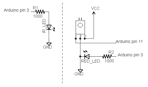
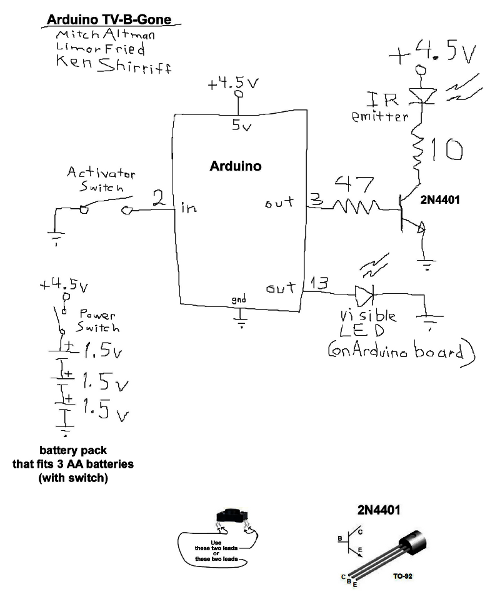
I've extended my Arduino IRremote library to support RC6 codes up to 64 bits long. Now your Arduino can control your Xbox by acting as an IR remote control. (The previous version of my library only supported 32 bit codes, so it didn't work with the 36-bit Xbox codes.) Details of the IRremote library are here.

Note: I don't actually have an Xbox to test this code with, so please let me know if the code works for you.

Download

This code is in my "experimental" branch since I'd like to get some testing before releasing it to the world. To use it:
  • Download the IRremote library zip file from GitHub from the Arduino-IRremote experimental branch.
  • Unzip the download
  • Move/rename the shirriff-Arduino-IRremote-nnnn directory to arduino-000nn/libraries/IRremote.

Sending an Xbox code

The following program simply turns the Xbox on, waits 10 seconds, turns it off, and repeats.
#include <IRremote.h>
IRsend irsend;
unsigned long long OnOff = 0xc800f740cLL;
int toggle = 0;

void sendOnOff() {
  if (toggle == 0) {
    irsend.sendRC6(OnOff, 36);
  } else {
    irsend.sendRC6(OnOff ^ 0x8000, 36);
  }
  toggle = 1 - toggle;
}
   
void setup() {}

void loop() {
  delay(10000);  // Wait 10 seconds
  sendOnOff();  // Send power signal
}
The first important thing to note is that the On/Off code is "unsigned long long", and the associated constant ends in "LL" to indicate that it is a long long. Because a regular long is only 32 bits, a 64-bit long long must be used to hold the 64 bit code. If you try using a regular long, you'll lose the top 4 bits ("C") from the code.

The second thing to notice is the toggle bit (which is explained in more detail below). Every time you send a RC5 or RC6 code, you must flip the toggle bit. Otherwise the receiver will ignore the code. If you want to send the code multiple times for reliability, don't flip the toggle bit until you're done.

Receiving an Xbox code

The following code will print a message on the serial console if it receives an Xbox power code. It will also dump the received value.
#include <IRremote.h>

int RECV_PIN = 11;
IRrecv irrecv(RECV_PIN);
decode_results results;

void setup()
{
  Serial.begin(9600);
  irrecv.enableIRIn(); // Start the receiver
}

void loop() {
  if (irrecv.decode(&results)) {
    if ((results.value & ~0x8000LL) == 0xc800f740cLL) {
      Serial.println("Got an OnOff code");
    }
    Serial.println(results.value >> 32, HEX);
    Serial.println(results.value, HEX);
    irrecv.resume(); // Receive the next value
  }
}
Two things to note in the above code. First, the received value is anded with ~0x8000LL; this clears out the toggle bit. Second, Serial.println is called twice, first to print the top 32 bits, and second to print the bottom 32 bits.

The output when sent power codes multiple times is:

Got an OnOff code
C
800FF40C
Got an OnOff code
C
800F740C
Got an OnOff code
C
...
Note that the received value is split between the two Serial.println calls. Also note that the output oscillates between ...F740C and ...FF40C as the sender flips the toggle bit. This is why the toggle bit must be cleared when looking for a particular value.

The IRremote/IRrecvDump example code has also been extended to display values up to 64 bits, and can be used for testing.

A quick description of RC6 codes

RC6 codes are somewhat more complicated than the usual IR code. They come in 20 or 36 bit varieties (that I know of). The code consists of a leader pulse, a start bit, and then the 20 (or 36) data bits. A 0 bit is sent as a space (off) followed by a mark (on), while a 1 bit is sent as a mark (on) followed by a space (off).

The first complication is the fourth data bit sent (called a trailer bit for some reason), is twice as long as the rest of the bits. The IRremote library handles this transparently.

The second complication is RC5 and RC6 codes use a "toggle bit" to distinguish between a button that is held down and a button that is pressed twice. While a button is held down, a code is sent. When the button is released and pressed a second time, a new code with one bit flipped is sent. On the third press, the original code is sent. When sending with the IRremote library, you must keep track of the toggle bit and flip it each time you send. When receiving with the IRremote library, you will receive one of two different codes, so you must clear out the toggle bit. (I would like the library to handle this transparently, but I haven't figured out a good way to do it.)

For details of the RC6 encoding with diagrams and timings, see SB projects.

The LIRC database

The LIRC project collects IR codes for many different remotes. If you want to use RC6 codes from LIRC, there a few things to know. A typical code is the Xbox360 file, excerpted below:
begin remote
  name  Microsoft_Xbox360
  bits           16
  flags RC6|CONST_LENGTH
  pre_data_bits   21
  pre_data       0x37FF0
  toggle_bit_mask 0x8000
  rc6_mask    0x100000000

      begin codes
          OpenClose                0x8BD7
          XboxFancyButton          0x0B9B
          OnOff                    0x8BF3
...
To use these RC6 code with the Arduino takes a bit of work. First, the codes have been split into 21 bits of pre-data, followed by 16 bits of data. So if you want the OnOff code, you need to concatenate the bits together, to get 37 bits: 0x37ff08bf3. The second factor is the Arduino library provides the first start bit automatically, so you only need to use 36 bits. The third issue is the LIRC files inconveniently have 0 and 1 bits swapped, so you'll need to invert the code. The result is the 36-bit code 0xc800f740c that can be used with the IRremote library.

The rc6_mask specifies which bit is the double-wide "trailer" bit, which is the fourth bit sent (both in 20 and 36 bit RC6 codes). The library handles this bit automatically, so you can ignore it.

The toggle_bit_mask is important, as it indicates which position needs to be toggled every other transmission. For example, to transmit OnOff you will send 0xc800f740c the first time, but the next time you will need to transmit 0xc800ff40c.

More details of the LIRC config file format are at WinLIRC.

Xbox codes

Based on the LIRC file, the following Xbox codes should work with my library:
OpenClose0xc800f7428XboxFancyButton0xc800ff464OnOff0xc800f740c
Stop0xc800ff419Pause0xc800f7418Rewind0xc800ff415
FastForward0xc800f7414Prev0xc800ff41bNext0xc800f741a
Play0xc800ff416Display0xc800f744fTitle0xc800ff451
DVD_Menu0xc800f7424Back0xc800ff423Info0xc800f740f
UpArrow0xc800ff41eLeftArrow0xc800f7420RightArrow0xc800ff421
DownArrow0xc800f741fOK0xc800ff422Y0xc800f7426
X0xc800ff468A0xc800f7466B0xc800ff425
ChUp0xc800f7412ChDown0xc800ff413VolDown0xc800ff411
VolUp0xc800ff410Mute0xc800ff40eStart0xc800ff40d
Play0xc800f7416Enter0xc800ff40bRecord0xc800f7417
Clear0xc800ff40a00xc800f740010xc800f7401
20xc800ff40230xc800f740340xc800ff404
50xc800f740560xc800ff40670xc800f7407
80xc800ff40890xc800f74091000xc800ff41d
Reload0xc800f741c

Key points for debugging

The following are the main things to remember when dealing with 36-bit RC6 codes:
  • Any 36-bit hex values must start with "0x" and end with "LL". If you get the error "integer constant is too large for 'long' type", you probably forgot the LL.
  • You must use "long long" or "unsigned long long" to hold 36-bit values.
  • Serial.print will not properly print 36-bit values; it will only print the lower 32 bits.
  • You must flip the toggle bit every other time when you send a RC6 code, or the receiver will ignore your code.
  • You will receive two different values for each button depending if the sender has flipped the toggle bit or not.

Control your mouse with an IR remote

You can use an IR remote to control your computer's keyboard and mouse by using my Arduino IR remote library and a small microcontroller board called the Teensy. By pushing the buttons on your IR remote, you can steer the cursor around the screen, click on things, and enter digits. The key is the Teensy can simulate a USB keyboard and mouse, and provide input to your computer.

How to do this

I built a simple sketch that uses the remote from my DVD player to move and click the mouse, enter digits, or page up or down. Follow these steps:
  • The hardware is nearly trivial. Connect a IR detector to the Teensy: detector pin 1 to Teensy input 11, detector pin 2 to ground, and detector pin 3 to +5 volts.
  • Install the latest version of my IR remote library, which has support for the Teensy.
  • Download the IRusb sketch.
  • In the Arduino IDE, select Tools > Board: Teensy 2.0 and select Tools > USB Type: Keyboard and Mouse.
  • Modify the sketch to match the codes from your remote. Look at the serial console as you push the buttons on your remote, and modify the sketch accordingly. (This is explained in more detail below.)
To reiterate, this sketch won't work on a standard Arduino; you need to use a Teensy.

How the sketch works

The software is straightforward because the Teensy has USB support built in. First, the IR library is initialized to receive IR codes on pin 11:
#include <IRremote.h>

int RECV_PIN = 11;
IRrecv irrecv(RECV_PIN);
decode_results results;

void setup()
{
  irrecv.enableIRIn(); // Start the receiver
  Serial.begin(9600);
}
Next, the decode method is called to receive IR codes. If the hex value for the received code corresponds to a desired button, a USB mouse or keyboard command is sent. If a code is not recognized, it is printed on the serial port. Finally, after receiving a code, the resume method is called to resume receiving IR codes.
int step = 1;
void loop() {
  if (irrecv.decode(&results)) {
    switch (results.value) {
    case 0x9eb92: // Sony up
      Mouse.move(0, -step); // up
      break;
    case 0x5eb92:  // Sony down
      Mouse.move(0, step); // down
      break;
...
    case 0x90b92:  // Sony 0
      Keyboard.print("0");
      break;
...
    default:
      Serial.print("Received 0x");
      Serial.println(results.value, HEX);
      break;
    }
    irrecv.resume(); // Resume decoding (necessary!)
  }
}
You may wonder where the codes such as 0x9eb92 come from. These values are for my Sony DVD remote, so chances are they won't work for your remote. To get the values for your remote, look at the serial console as you press the desired buttons. As long as you have a supported remote type (NEC, Sony, RC5/6), you'll get the hex values to put into the sketch. Simply copy the hex values into the sketch, and perform the desired action.

There are a few details to note. If your remote uses the RC5 or RC6 format, there are actually two different codes assigned to each button, and the remote alternates between them. Push the button twice to see if you'll need to use two different codes. If you want to send a non-ASCII keyboard code, such as Page Down, you'll need to use a slightly more complex set of commands (documentation). For example, the following code sends a Page UP if it receives a RC5 Volume Up from the remote. Note that there are two codes for volume up, and note that KEY_PAGE_UP is sent, followed by 0 (no key).

    case 0x10: // RC5 vol up
    case 0x810:
      Keyboard.set_key1(KEY_PAGE_UP);
      Keyboard.send_now();
      Keyboard.set_key1(0);
      Keyboard.send_now();
      break;

Improvements

My first implementation of the sketch as described above was very easy, but there were a couple displeasing things. The first problem was the mouse movement was either very slow (with a small step size) or too jerky (with a large step size). Second, if you press a number on the remote, the keyboard input rapidly repeats because the IR remote repeatedly sends the IR code, so you end up with "111111" when you just wanted "1".

The solution to the mouse movement is to implement acceleration - as you hold the button down, the mouse moves faster. This was straightforward to implement. The sketch checks if the button code was received within 200ms of the previous code. If so, the sketch speeds up the mouse movement by increasing the step size. Otherwise it resets the step size to 1. The result is that tapping the button gives you fine control by moving the mouse a little bit, while holding the button down lets you zip across the screen:

    if (millis() - lastTime > GAP) {
      step = 1;
    } 
    else if (step > 20) {
      step += 1;
    }
Similarly, to prevent the keyboard action from repeating, we only output keypresses if the press is more then 200ms after the previous. This results in a single keyboard action no matter how long a button is pressed down. The same thing is done to prevent multiple mouse clicks.
 if (millis() - lastTime > GAP) {
        switch (results.value) {
        case 0xd0b92:
          Mouse.click();
          break;
        case 0x90b92:
          Keyboard.print("0");
          break;
...

Now you can control your PC from across the room by using your remote. Thanks to Paul Stoffregen of PJRC for porting my IR remote library to the Teensy and sending me a Teensy for testing.

IRremote library now runs on the Teensy, Arduino Mega, and Sanguino

Thanks to Paul Stoffregen of PJRC, my Arduino IR remote library now runs on a bunch of different platforms, including the Teensy, Arduino Mega, and Sanguino. Paul has details here, along with documentation on the library that I admit is better than mine.

I used my new IRremote test setup to verify that the library works fine on the Teensy. I haven't tested my library on the other platforms because I don't have the hardware so let me know if you have success or run into problems.

Download

The latest version of the IRremote library with the multi-platform improvements is on GitHub. To download and install the library:
  • Download the IRremote library zip file from GitHub.
  • Unzip the download
  • Move/rename the shirriff-Arduino-IRremote-nnnn directory to arduino-000nn/libraries/IRremote.

Thanks again to Paul for adding this major improvement to my library and sending me a Teensy to test it out. You can see from the picture that the Teensy provides functionality similar to the Arduino in a much smaller package that is also breadboard-compatible; I give it a thumbs-up.

Testing the Arduino IR remote library

I wrote an IR remote library for the Arduino (details) that has turned out to be popular. I want to make sure I don't break things as I improve the library, so I've created a test suite that uses a pair of Arduinos: one sends data and the other receives data. The receiver verifies the data, providing an end-to-end test that the library is working properly.

Overview of the test

The first Arudino repeatedly sends a bunch of IR codes to the second Arduino. The second Arduino verifies that the received code is what is expected. If all is well, the second Arduino flashes the LED for each successful code. If there is an error, the second Arudino's LED illuminates for 5 seconds. The test cycle repeats forever. Debugging information is output to the second Arduino's serial port, which is helpful for tracking down the cause of errors.

Hardware setup

The test hardware is pretty simple: one Arduino transmits, and one Arduino receives. An IR LED is connected to pin 3 of the first Arduino to send the IR code. An IR detector is connected to pin 11 of the second Arduino to receive the IR code. A LED is connected to pin 3 of the second Arduino to provide the test status.
schematic of test setup

Details of the test software

One interesting feature of this test is the same sketch runs on the sending Arduino and the receiving Arduino. The test looks for an input on pin 11 to decide if it is the receiver:
void setup()
{
  Serial.begin(9600);
  // Check RECV_PIN to decide if we're RECEIVER or SENDER
  if (digitalRead(RECV_PIN) == HIGH) {
    mode = RECEIVER;
    irrecv.enableIRIn();
    pinMode(LED_PIN, OUTPUT);
    digitalWrite(LED_PIN, LOW);
    Serial.println("Receiver mode");
  } 
  else {
    mode = SENDER;
    Serial.println("Sender mode");
  }
}
Another interesting feature is the test suite is expressed very simply:
  test("SONY4", SONY, 0x12345, 20);
  test("SONY5", SONY, 0x00000, 20);
  test("SONY6", SONY, 0xfffff, 20);
  test("NEC1", NEC, 0x12345678, 32);
  test("NEC2", NEC, 0x00000000, 32);
  test("NEC3", NEC, 0xffffffff, 32);
...
Each test call has a debugging string, the type of code to send/receive, the value to send/receive, and the number of bits.

On the sender, the testmethod sends the code, while on the receiver, the method verifies that the proper code is received. The SENDER code calls the appropriate send method based on the type, and then delays before the next test. The RECEIVER code waits for a code. If it's correct, it flashes the LED. Otherwise, it sets the state to ERROR.

void test(char *label, int type, unsigned long value, int bits) {
  if (mode == SENDER) {
    Serial.println(label);
    if (type == NEC) {
      irsend.sendNEC(value, bits);
    } 
    else if (type == SONY) {
...
    }
    delay(200);
  } 
  else if (mode == RECEIVER) {
    irrecv.resume(); // Receive the next value
    unsigned long max_time = millis() + 30000;
    // Wait for decode or timeout
    while (!irrecv.decode(&results)) {
      if (millis() > max_time) {
        mode = ERROR; // timeout
        return;
      }
    }
    if (type == results.decode_type && value == results.value && bits == results.bits) {
      // flash LED
    } 
    else {
      mode = ERROR;
    }
  }
}
The trickiest part of the code is synchronizing the sender and the receiver. This happens in loop(). The receiver waits for 1 second without any transmission, while the sender pauses for 2 seconds after each time through the tests. Thus, the receiver will wait while the sender is running through tests, and then will start listening just before the sender starts the next cycle of tests. One other thing to point out is if there is an error, the receiver will skip through all the remaining tests, light the LED to indicate the error, and then will wait to sync up again. This avoids the problem of one bad test getting the receiver permanently out of sync; the receiver is able to re-sync and continue successfully after a failed test.
void loop() {
  if (mode == SENDER) {
    delay(2000);  // Delay for more than gap to give receiver a better chance to sync.
  } 
  else if (mode == RECEIVER) {
    waitForGap(1000);
  } 
  else if (mode == ERROR) {
    // Light up for 5 seconds for error
    mode = RECEIVER;  // Try again
    return;
  }
The test also includes some raw mode tests. These are a bit more complicated, since I want to test the various combinations of sending and receiving in raw mode.

Download and running

I'm gradually moving my development to GitHub at https://github.com/shirriff/Arduino-IRremote.

The code fragments above have been slightly abbreviated; the full code for the test sketch is here.

To download the library and try out the two-Arduino test:

  • Download the IRremote library zip file.
  • Unzip the download
  • Move/rename the shirriff-Arduino-IRremote-nnnn directory to arduino-000nn/libraries/IRremote. The test sketch is in examples/IRtest2.

To run the test, install the sketch on two Arduinos. The test should automatically start running. Note that it is a bit tricky to use two Arduinos at once. They will probably get assigned different serial ports, and you can switch ports using the Tools menu. If you get confused, you can plug one Arduino in at a time, and then you can be sure about which one is getting installed.

My plan is to do more development on the library, now that I have a reasonably solid test suite and I can be more confident that I don't break things. Let me know if there are specific features you'd like.

Thanks go to SparkFun for giving me the second Arduino that made this test possible.

Improved Arduino TV-B-Gone

Oct 2016: An updated version of the code is on github, thanks to Gabriel Staples.

The TV-B-Gone is a tiny infrared remote that can turn off almost any TV. A while ago, I ported the TV-B-Gone software to the Arduino; for details on the port and how it works see my previous post on the Arduino TV-B-Gone.

Mitch Altman, the inventor of the TV-B-Gone, made some improvements to the code for a weekly TV-B-Gone constructing workshop in San Francisco at Noisebridge. If you're in the San Francisco area and are interested in the TV-B-Gone, you might want to check it out.

The main bug fix in the new version is the European codes will now work (if you ground pin 5). (The problem was a bunch of #ifdefs to fit the codes into the ATtiny's limited memory; taking out the #ifdefs fixed the problems.) Pressing the trigger button during transmission will now restart the codes. The delay between codes was increased, which should make transmission more reliable. The Arduino's processor will now sleep when not transmitting (thanks to ka1kjz). (Unfortunately, the rest of the Arduino components are still draining power, so sleep mode will be more useful with stripped-down Arduino variants.)

Important: the pins have been changed around in the new version (to avoid conflicts with the serial port). Pin 2 is now the trigger switch, Pin 3 is the IR output, and Pin 5 is grounded if you want European codes. If you built an Arduino TV-B-Gone before and want to use the new code, make sure you connect to the right pins.

Here's Mitch Altman's schematic for the Arduino TV-B-Gone (click for larger): Arduino TV-B-Gone schematic

To build the Arduino TV-B-Gone, follow the above schematic and download the sketch from github. My previous post on the Arduino TV-B-Gone has more information on wiring it up, if you need it.

Inside the Firesheep code: how it steals your identity

You may have heard about Firesheep, a new Firefox browser add-on that lets anyone easily snoop over Wi-Fi and hijack your identity for services such as Facebook and Twitter. This is rather scary; if you're using Wi-Fi in a coffee shop and access one of these sites, the guy in the corner with a laptop could just go click-click and be logged in as you. He could then start updating your Facebook status and feed for instance. Even if you log in securely over SSL, you're not protected.

The quick explanation

Bad guy at computer
The Firesheep site gives an overview of its operation: after you log into a website, the website gives your browser a cookie. By snooping on the Wi-Fi network, Firesheep can grab this cookie, and with the cookie the Firesheep user can hijack your session just as if they are logged in as you.

You may be wondering what these mysterious cookies are. Basically, a cookie is a short block of characters. The cookie consists of a name (e.g. "datr") and a value (e.g. "QKvHTCbufakBOZi5FOI8RTXQ"). For a login cookie, the website makes up a unique value each time someone logs in and sends it to the browser. Every time you load a new page, your browser sends the value back to the website and the website knows that you're the person who logged on. This assumes a couple things: first, that a bad guy can't guess the cookie (which would be pretty hard for a long string of random characters), and second, that nobody has stolen your cookie.

Web pages usually use https for login pages, which means SSL (Secure Socket Layer) is used to encrypt the data. When using SSL, anyone snooping will get gibberish and can't get your userid and password. However, because https is slower than regular http (because all that encryption takes time), websites often only use the secure https for login, and use insecure http after that. Banking sites and other high-security sites typically use https for everything, but most websites do not.

The consequence is that if you're using unencrypted Wi-Fi, and the website uses insecure http, it's very easy for anyone else on the Wi-Fi network to see all that data going to and from your computer, including the cookies. Once they have your cookie for a website, they can impersonate you on that website.

This insecurity has been known for a long time, and it's easy for moderately knowledgeable people to use a program such as tcpdump or wireshark to see your network traffic. What Firesheep does is makes this snooping so easy anyone can do it. (I would recommend you don't do it, though.)

The detailed explanation

A few things about Firesheep still puzzled me. In particular, how do other people's network packets get into your browser for Firesheep to steal?

To get more information on how Firesheep works, I took a look at the source code. Since it's open source, anyone can look at the code at http://github.com/codebutler/firesheep.

The packet sniffing code is in the firesheep/backend/src directory. This code implements a little program called "firesheep-backend" that uses the pcap library to sniff network traffic and output packets as JSON.

pcap is a commonly-used packet capture library that will capture data packets from your network interface. Normally, a network interface ignores network packets that aren't intended to be received by your computer, but network interfaces can be put into "promiscuous mode" (note: I didn't invent this name) and they will accept any incoming network data. Normally packet capture is used for testing and debugging, but it can also be used for evil snooping. (As an aside, the unique MAC address - the number such as 00:1D:72:BF:C9:55 on the back of a network card - is used by the network interface to determine if the packet is meant for it or not.)

Going back to the code, the http_sniffer.cpp gets a data packet from the pcap library, looks for TCP packets (normal internet data packets), and then http_packet.cpp uses http-parser to parse the packet if it's an HTTP packet. This breaks a HTTP packet into its relevant pieces including the cookies. Finally, the relevant pieces of the packet are output in JSON format (a JavaScript-based data format that can be easily used by the JavaScript plugin in the browser).

That explains how the packets get captured and converted into a format usable by the Firefox add-on. Next I will show how Firesheep knows how to deal with the cookies for a particular website.

The xpi/handlers directory has a short piece of JavaScript code for each website it knows how to snoop. For instance, for Flickr:

// Authors:
//   Ian Gallagher 
register({
  name: 'Flickr',
  url: 'http://www.flickr.com/me',
  domains: [ 'flickr.com' ],
  sessionCookieNames: [ 'cookie_session' ],

  identifyUser: function () {
    var resp = this.httpGet(this.siteUrl);
    var path = resp.request.channel.URI.path;
    this.userName = path.split('/')[2];
    this.userAvatar = resp.body.querySelector('.Buddy img').src;
  }
});
This code gives the name of the website (Flickr), the URL to access, the domain of the website, and the name of the session cookie. The session cookie is the target of the attack, so this is a key line. Next is a four line function that is used to fetch the user's name and avatar (i.e. picture) from the website once the cookie is obtained.

Firesheep currently has handlers for about 25 different websites. By writing a short handler similar to the above, new websites can easily be hacked (if their cookie is accessible).

The visible part of the extension that appears in the browser is in firesheep/xpi/chrome. The most interesting parts are in the content subdirectory. ff-sidebar.js implements the actual sidebar and displays accounts as they are sniffed.

The "meat" of the JavaScript plugin is in firesheep/xpi/modules. Firesheep.js implements the high-level operations such as startCapture() and stopCapture(). FiresheepSession.js is the glue between the plugin and the firesheep-backend binary that does the actual packet collection. Finally FiresheepWorker.js does the work of reading the packet summary from firesheep-backend (via JSON) and processing it by checking the appropriate website-specific handler and seeing if the desired cookie is present.

Finally, how do the pieces all get put together into the add-on that you can download? Firefox extensions are explained on the developer website. The install.rdf file (in firesheep/xpi) gives the Firefox browser the main information about the extension.

Well, that summarizes how the Firesheep plugin works based on my analysis of the code. Hopefully this will help you realize the risk of using unsecured Wi-Fi networks!