Understanding Sony IR remote codes, LIRC files, and the Arduino library

This article describes how to understand Sony IR codes and how to get them from the LIRC files. The article is intended to describe codes for use with my Arduino infrared remote library, but the information should be generally applicable. This article is aimed at the hardware hacker and assumes that you are familiar with binary and hexadecimal, so be warned :-)

One key point of this article is that there are three different ways to interpret the same IR signal and turn it into a hex code. Understanding these three ways will allow you to get codes from different sources and understand them correctly.

The IR transmission of the code

When you press a button on a Sony remote control, an infrared signal is transmitted. This transmission consists of a 40kHz signal which is turned on and off in a particular pattern. Different buttons correspond to different codes, which cause the signal to be turned on and off in different patterns.

The following waveform shows the IR code transmitted for STOP on my Sony CD remote control (RM-DC335). When the signal is high, a 40 kHz IR signal is transmitted, and when the signal is low, nothing is transmitted. In other words, the signal is actually rapidly turning on and off when it appears to be on in the figure. (The IR receiver demodulated the signal, so you don't see the 40 kHz transitions.)
IR transmission for a Sony remote control
A Sony IR signal starts with 2400 microseconds on and 600 microseconds off; that's the first wide pulse. A "1" bit is transmitted with 1200 microseconds on and 600 microseconds off, while a "0" bit is transmitted with 600 microseconds on and 600 microseconds off. (This encoding is also called SIRC or SIRCS encoding.)

You may notice the "on" parts of the waveform appear wider than the "off" parts, even when both are supposed to be 600 microseconds. This is a result of the IR receiver, which switches on faster than switching off.

The above waveform represents one transmission of a 12-bit code. This transmission is normally repeated as long as the button is held down, and a minimum of three times. Each transmission starts 45ms after the previous one started. The Sony protocol also supports 15 and 20 bit codes, which are the same as above except with more bits.

For more information on the low-level transmission of Sony codes, see sbprojects.net.

Three ways to interpret the codes

The Sony encoding seems straightforward, but there are several different ways the signal can be interpreted. I will call these official decoding, bit decoding, and bit-1 decoding. Different sources use any of these three, which can cause confusion. I will explain these three decodings, using the previous waveform as an example.

Official decoding

Official Sony decoding
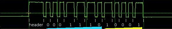
The "official" Sony protocol views the 12-bit code as 7 command bits and 5 address or device bits, transmitted least-significant-bit first (i.e. "backwards"). The device bits specify the type of device receiving the code, and the command bits specify a particular command for this device. In this example, the device bits (yellow) are 10001 when read right-to-left, which is 17 decimal. The command bits (blue) are 0111000 when read right-to-left, which is 56 decimal. The device value 17 corresponds to a CD player, and the command 56 corresponds to the STOP command (details).

Sony 15 bit codes are similar, with 7 command bits and 8 device bits. Sony 20 bit codes have 7 command bits, 5 device bits, and 8 extended device bits.

Bit decoding

Decoding Sony IR code as a sequence of bits
Many IR decoders just treat the signal as a sequence of bits, most-significant-bit first. I will call this bit decoding. Applying this interpretation to the above code, the code is interpreted as 0001 1101 0001 binary, or 1d1 hex, or 465 in decimal. Note that the last bit doesn't really consist of 1200 microseonds on and 600 microseconds off; it consists of 1200 microseconds on followed by a lot of time off. In other words, the transmission is off for 600 microseconds and then continues to be off until the next code is transmitted.

An alternative but equivalent interpretation is to view the code as a 2400 microsecond header, followed by 12 bits, where each bit is off then on (rather than on then off). A "1" bit is 600 microseconds off and 1200 microseconds on, while a "0" bit is 600 microseconds off and 600 microseconds on. This yields the same value as before (232 decimal), but avoids the special handling of the last bit.
Short one bit decoding

Bit-1 decoding

Short one bit decoding
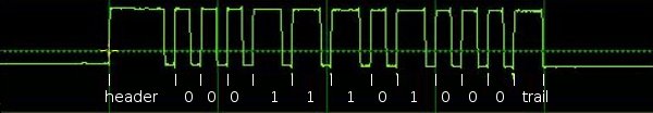
Many IR decoders drop the last bit, which I will call bit-1 decoding. Because the last bit doesn't end nicely with 600 microseconds off, some IR decoding algorithms treat the signal as 11 bits of data, ending with 600 microseconds on as a trailer. In this interpretation, the above code is 000 1110 1000 binary, or 0e8 hex, or 232 decimal. (Note that doubling this value and adding 1 yields the previous decoding of 465.)

Discussion

Is the code really 17/44 or 465 or 232? The official decoding is "right" in the sense that it is what the manufacturer intends. In addition, it reveals the internal structure of the code and the codes make more sense. For instance, the buttons 1-9 have consecutive codes with the official decoding, but not with the others. The other decodings are fine to use as long as you're consistent; the main thing is to understand that different sources use different decodings. My Arduino library uses the second bit decoding interpretation. The different decodings can be converted from one form to another with binary arithmetic.

Getting codes from a remote

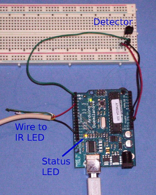
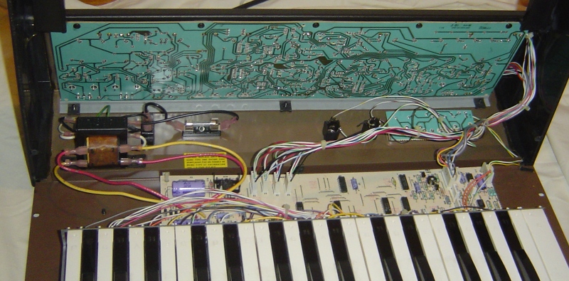
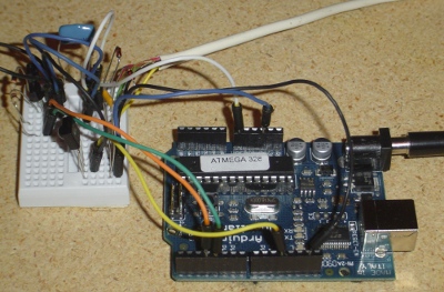
Probably the easiest way to get the codes for your device is to use your existing remote control and see what codes it transmits. You can use my Arduino IR library to do the decoding, with the IRrecvDump demo program. Take a 3-pin IR decoder, hook it up to an Arduino, and then you can read the values for each button press on the serial port.

Alternatively, you can look at the transmitted codes with an oscilloscope. For the diagrams above, I used an IR receiver module connected to two resistors (to drop the voltage), connected to the line input of my PC. I used the Zeitnitz Soundcard Oscilloscope program to display the signal. This lets you see exactly what is being transmitted, but you will need to stare at the screen, write down a bunch of 0's and 1's, and convert the binary value to get your codes.

Getting codes from LIRC files

The best source for IR codes that I've found is the Linux Infrared Remote Control project (lirc.org), which has a huge collection of config files for various remotes. (LIRC also includes a large collection of device drivers for many types of IR input/output hardware, and a software library.)

The LIRC config file format is documented at WinLIRC, but I will walk through some examples.

Bit decoding

The RM-S530 LIRC file treats the codes as 12 bits long, using what I call bit decoding:
begin remote

  name  Sony
  bits           12
  flags SPACE_ENC|CONST_LENGTH
  eps            30
  aeps          100

  header       2470   557
  one          1243   556
  zero          644   556
  gap          45076
  min_repeat      2
  toggle_bit      0


      begin codes
          sleep                    0x0000000000000061
          cd_stop                  0x00000000000001D1
...
This file indicates that each entry is 12 bits long. A header consists of on for 2470 microseconds and off for 557 microseconds. A one bit consists of on for 1243 microseconds and off for 556 microseconds. A zero bit consists of on for 644 microseconds and off for 556 microseconds. Codes are repeated a minimum of 2 more times, with a gap of 45076 microseconds from start to start as the codes are constant length (CONST_LENGTH).

You may be wondering why these time values don't match the official values of 2400, 1200, and 600 microseconds. First, the LIRC data is generally measured from actual remotes, so the real-world timings don't quite match the theory. Second, IR sensors have some lag in detecting "on" and "off", and they typically stretch out the "on" time by ~100 microseconds, shortening the "off" time equally.

The LIRC file then lists the hex code associated with each button. For example the CD STOP code is hex 1D1, which is the same value as described earlier.

Bit-1 decoding

The LIRC file for the RM-D302 remote treats the codes as 11 bits and a trailing pulse. This is what I call the bit-1 decoding:
begin remote

  name  RM-D302
  bits           11
  flags SPACE_ENC|CONST_LENGTH
  eps            30
  aeps          100

  header       2367   638
  one          1166   637
  zero          565   637
  ptrail       1166
  gap          45101
  min_repeat      2
  toggle_bit      0


      begin codes
          cd_stop                  0x00000000000000E8
The key differences with the previous file are the ptrail field, indicating a trailing pulse of 1166 microseconds; and the bit count of 11 instead of 12. Note that the code value is different from the first file, even thought the IR transmission is exactly the same. The hex code 0E8 is the same as described earlier under bit-1 decoding.

Pre_data and post_data bits

Some LIRC files break apart the codes into constant pre_data bits, the code itself, and constant post_data bits. For instance, the file for my RM-D335 remote:
begin remote

  name  SONY
  bits            7
  flags SPACE_ENC
  eps            20
  aeps            0

  header       2563   520
  one          1274   520
  zero          671   520
  ptrail       1274
  post_data_bits  4
  post_data      0x8
  gap          25040
  min_repeat      2

      begin codes
          CONTINUE                 0x000000000000005C
...
          STOP                     0x000000000000000E
...
This file indicates that each code entry is 7 bits long, but there are also 4 post data bits. This means that after transmitting the 7 bits for the code, 4 additional bits are transmitted with the "post data" hex value 0x8, i.e. 1000 binary.

Putting this together the STOP button has the hex value 0E, which corresponds to the seven bits 000 1110. This is followed by four post data bits 1000, so the total transmission is the eleven bits 000 1110 1000, which is 0E8 hex, the same as before for the bit-1 decoding.

One more thing to notice in this LIRC file is it doesn't have the CONST_LENGTH flag, and the gap is 25ms instead of 45ms. This indicates the gap is from the end of one code to the start of the next, rather than from the start of one code to the start of the next. Specifying a gap between codes isn't how Sony codes are actually defined, it's close enough.

LIRC summary

Note that these LIRC files all indicate exactly the same IR transmission; they just interpret it differently. The first file defines the STOP code as 1D1, the second as E8, and the third as 0E.

What does this mean to you? If you want to get a Sony code from a LIRC file and use it with the Arduino library, you need to have a 12 bit (or 15 or 20 bit) code to pass to the library (bit decoding). Look up the code in the file and extract the specified number of bits. If there are any pre_data or post_data bits, append them as appropriate. If the result is one bit short and the LIRC file has a ptrail value, append a 1 bit on the end to convert from bit-1 decoding to bit decoding. Convert the result to hex and you should have the proper code for your device, that can be used with the Arduino library.

Getting codes from hifi-remote.com

The most detailed site I've found on Sony codes specifically is hifi-remote.com/sony. An interesting thing about this site is it analyzes the structure of the codes. While the LIRC files just list the codes, the hifi-remote site tries to explain why the codes are set up the way they are.

Note that this site expresses codes in Sony format, i.e. most-significant-bit first, and separating the device part of the code from the command part of the code. Also for a 20-bit Sony code, the 13 bit device code is expressed as a 5 bit value and an 8 bit value separated by a period. As a result, you may need to do some binary conversion and reverse the bits to use these codes.

To work through an example, I can look up the data for a Sony CD. There are multiple device codes, but assume for now I know my device code is 17. The table gives the code 56 for STOP. Convert 56 to the 7 bit binary value 0111000 and reverse it to get 0001110. Convert 17 to the 5 bit binary value 10001 and reverse it to get 10001. Put these together to et 000111010001, which is 1D1 hex, as before.

To work through a 20-bit example, if I have a Sony VCR/DVD Combo with a device code of 26.83, the site tells me that the code for "power" is 21. Convert 21 to a 7 bit binary value, 26 to a 5 bit binary value, and 83 to a 8 bit binary value. Then reverse and concatenate the bits: binary 1010100 + 01011 + 11001010, which is a8bca in hex. To confirm, the RMT-V501A LIRC file lists power as A8B with post_data of CA.

To use this site, you pretty much have to know the device code for your device already. To find that, obtain a code for your device (e.g. from your existing remote or from LIRC), split out and reverse the appropriate bits, and look up the device code on the site. Alternatively, there are only a few different device codes for a particular type of device, so you can just try them all and see what works.

This site also has information on "discrete codes". To understand discrete codes, consider the power button on a remote that toggles between "on" and "off". This may be inconvenient for automated control, since without knowing the current state, you don't know if sending a code will turn the device on or off. The solution is the "discrete code", which provides separate "on" and "off" codes. Discrete codes may also be provided for operations such as selecting an input or mode. Since these codes aren't on the remote, they are difficult to obtain.

Other sites

Additional config files are available at irremote.psiloc.com. These are in LIRC format, but translated to XML. The site remotecentral.com has a ton of information on remotes, but mostly expressed in proprietary formats.

Conclusion

Hopefully this will clear up some of the confusion around Sony remote codes, without adding additional confusion :-)

Some similar and confusing Spanish words

While trying to learn Spanish, I find a few Spanish words are similar to other words and keep confusing me. This article summarizes them, mostly for my on benefit in learning to distinguish them, but maybe you'll find it useful too. (Yes, this is a big tangent from my usual blog topics.)
  • llegar - to arrive.
  • llenar - to fill. (My secret to remembering this is that llenar is the root in chile relleno, a stuffed chile.)
  • llevar - to carry.
There are some verb conjugations that are the same or confusingly similar to other words:
  • fuera - outside.
  • fuera - imperfect subjunctive of ser or ir.
  • siento - I sit (from sentar).
  • siento - I feel (from sentir). A bunch of other conjugations are confusing because the present for one is the subjunctive for the other: sientas/sientes, sienta/siente, sienten/sientan, sentamos/sentimos.
  • ira - anger.
  • irá - future of ir.

Detecting an IR Beam Break with the Arduino IR Library

One reader asked how to use my Arduino Infrared Library to detect breakage of an IR beam. The answer was too long for the comments section, so I've extended into a blog post. One straightforward way is to use the library to modulate an IR LED at 38kHz, and use a standard IR detector module to detect the signal. The output from the module can be simply read as a digital input.

Here is a simple sketch to do that. The IR LED is connected to pin 3 through a 100 ohm resistor, the detector is connected to pin 2, and a status LED is connected to pin 13 (if your Arduino board doesn't have it already.) To create the modulated output, simply call irsend.enableIROut(38); to set the PWM to 38kHz, and then irsend.mark(0) to send a mark (i.e. turn the output on). The loop simply reads the input from the detector, inverts it (since the detector is active-low), and writes it to the status LED.

#include <IRremote.h>

#define PIN_IR 3
#define PIN_DETECT 2
#define PIN_STATUS 13

IRsend irsend;
void setup()
{
  pinMode(PIN_DETECT, INPUT);
  pinMode(PIN_STATUS, OUTPUT);
  irsend.enableIROut(38);
  irsend.mark(0);
}

void loop() {
  digitalWrite(PIN_STATUS, !digitalRead(PIN_DETECT));
}
You should see the pin 13 LED light up when the IR receiver detects an infrared signal, and go dark when the receiver does not detect an infrared signal. The circuit is basically trivial, but there's a schematic at my original article if you need one. The following picture shows the detector setup. Note the illuminated status LED.
IR detector circuit
If the circuit doesn't work, first use a cell phone camera to verify that the infrared LED is lit. If the LED is not lit, try reversing it. Here's my cellphone's view of the illuminated LED:
illuminated infrared LED
Next, point a TV remote control at the detector and make sure the status LED flashes. If the status LED doesn't come on, make sure you wired the detector properly, and connected to input 2 of the Arduino. If the status LED won't turn off when you break the beam, you probably aren't blocking the IR signal well enough. The detector is very sensitive, and IR bounces off many things, so you may need to separate the LED and detector by several feet and make sure you're fully blocking the IR beam. Note that the library assumes you're using a ATmega168/328, so you're on your own if you have a different processor.

The tricky part of this is the optics - figuring out how to set up the LED and receiver so the beam gets interrupted when you want it to. Also, you'll probably want to modify the detection logic to do something more interesting than just set the status LED, but that's left as an exercise for the reader :-)

Fixing my Concertmate MG-1 Synth

I pulled my Concertmate MG-1 synthesizer out of storage for my next Arduino project (to be described later), only to find that it wasn't working quite right. This posting briefly describes how I fixed it, in case anyone else has a similar problem.
Concertmate MG-1 Synthesizer
The main problem with the MG-1 was a loud click (a bit like a kick drum) when I pressed or released a key. It sounded suspiciously like a DC signal being applied to a speaker. The second problem was that when I set the contour for an attack and decay, the note got louder and softer, but as the note got softer it was replaced with a buzz at the frequency of oscillator 1.

Conveniently, the Service Manual is available online. I studied it and the schematic, and my first guess was that there was a DC offset going into the CA3080 amplifier, resulting in an amplified DC signal in the output. The CA3080 is not a normal amplifier but an operational transconductance amplifier, an unusual amplifier where the current on a control input controls the amplification of the input signal (more info). In this case, it is used as a voltage-controlled amplifier, allowing the contour signal to control the output.

In the schematic below, op-amps U10A and U10B feed the differential output signal into the 38080 amplifier. Pin 5 of the 3080 receives the contour signal to provide the attack and decay when you press a key. This signal controls how much the inputs are amplified. The output goes into the master volume control, and then to the synthesizer outputs. If there's a DC offset between the input pins 2 and 3, there will be an amplified DC offset at the output.
MG-1 Output Schematic
Fortunately, there is a VCA Balance Trim adjustment to trim any DC offset, and the manual describes how to adjust this. I opened up the MG-1 and adjusted this, but unfortunately it made no difference at all.

Next, I stared at the schematic for the contour generator that feeds into the CA3080 amplifier, but couldn't see how that could be going wrong. I measured the inputs to the CA3080 with an oscilloscope and found they all seemed normal. However, the output showed a 3.75V DC jump when the key turned on, which explained the click. In addition, the contour input showed it was picking up some crosstalk from the oscillator 1 trace that runs next to it, and this was being amplified into the buzzing noise.

All signs pointed to a problem with the CA3080 amplifier chip, which was somehow amplifying a big DC signal. Unfortunately, the CA3080 is no longer being manufactured and is hard to obtain. Fortunately, by some bizarre twist of fate, I happened to have one in my rather small box of parts.

The picture below shows the two main circuit boards. The upper board is the sound generation, filtering, and amplification, while the lower board has the power supply, keyboard, control, and polyphonic sound.
MG-1 internals
I removed the circuit board, soldered in the new CA3080, got the switches centered just right so the circuit board could be replaced, and put it back together. Unfortunately, I didn't get any output at all. I was afraid I'd somehow destroyed my rare CA3080 chip, but fortunately discovered that if the switches are in intermediate positions, you don't get any signal. I returned the switches to their proper positions and all was well.

In conclusion, I succeeded in fixing my MG-1 and getting that lovely, rich Moog sound.

Don't walk! Controlling a pedestrian sign with an Arduino

My latest project is controlling a pedestrian sign with an Arduino, so it will automatically step through the states of walk, flashing don't walk, and solid don't walk. In addition, I added infrared remote control support so I can use a remote control to turn the sign on and off, set it to a particular state, or start the cycle.

The hardware

A pedestrian sign controlled by an Arduino.
The pedestrian sign is controlled by two relays that switch 120-volt AC on and off; one powers the "walk" part of the sign, and one powers the "don't walk" part.
The Arduino circuitry.
The Arduino drives the relays through transistors connected to 9-volt supply. Technically the relays are 12-volt relays, but they seem to work with 9 volts. I used one 10A relay, and one 5A relay, just because that's what I had around.
The relays controlling the sign.
Needless to say, 120 volts can be dangerous, both to yourself and to your Arduino. Follow the appropriate precautions. I make no claims about the safety of this circuit.

The remote control input uses an IR detector module connected to the Arduino. For details on the IR detection, see the article on my IRremote library. The code section below describes how to modify the code to support different remotes.
Schematic of the pedestrian sign controller.

I found the IR detector didn't work super-reliably when the sign was turned on. This was probably due to high-frequency electrical interference since adding some capacitors helped, but the light itself could have been interfering. I probably should have wired up the relay circuit and the IR detector circuit farther apart to minimize interference, as I did when controlling a DC motor.

Inside the pedestrian sign

You may be curious about what's inside a pedestrian sign. What I have is the lighting unit; this goes inside the metal case that you see attached to a traffic pole. (In case you're worried, I didn't steal this from an intersection. I got it on ebay from some city that was replacing their units with more efficient LED units.)

Inside the signal are two neon tubes, roughly the shape of the hand and the pedestrian; generating red and white light respectively. I use "neon tube" in the generic sense; I don't know what gas is actually inside. Note that the tubes are not colored and the cover is clear; the red color is entirely from the gas discharge.
The neon tubes the pedestrian sign
Beneath the tubes are two high-voltage driver circuits, one for each tube. Each driver circuit runs off 120V AC and has an oscillator (using a LM2903 comparator) driving a flyback transformer through a power transistor (under the board). This generates multi-kilovolts to drive the tubes. Note at the far left the standoffs that keep the output wire an inch above the circuit board due to the high voltage. Needless to say, I stay away from the circuitry while it is operating. Each driver board has a separate AC input; when AC is fed in, the tube lights up. One drawback of the driver circuitry is it makes a high-pitched whine when turned on. I originally planned to use the sign to indicate unittest pass/fail status, but it was too annoying to people nearby.
The power circuits for the pedestrian sign

The code

The Arduino code is available at IRtraffic.pde and has two main functions: IR processing and light cycle processing.

In the IR code, the IR remote is used to select one of five states: walk illuminated, blinking don't walk, don't walk illuminated, off, or cycling (which goes through the first three states). The IR functionality uses my IRremote library to decode the output from a remote control.

The code has the values for a particular remote control hard-coded. I used a Sony DVD remote:

#define OFF_CODE 0x1CB92 // Stop on Sony DVD remote
#define WALK_CODE 0xB92 // 1 on Sony DVD remote
#define BLINK_CODE 0x80b92 // 2 on Sony DVD remote
#define DONT_CODE 0x40b92 // 3 on Sony DVD remote
#define CYCLE_CODE 0x4CB92 // Play on Sony DVD remote
The first part of the loop function calls the IR library to see if an IR signal has been decoded. If so, it switches to the appropriate mode. If an unexpected IR value is encountered, it is printed to the serial port.
void loop() {
  // Process the IR input, if any
  if (irrecv.decode(&results)) {
    if (results.value == WALK_CODE) {
      Serial.write("Walk\n");
      mode = MODE_WALK;
      cycle = false;
    } 
    else if (results.value == DONT_CODE) {
      Serial.write("Don't walk\n");
      mode = MODE_DONT;
      cycle = false;
    } 
    else if (results.value == OFF_CODE) {
      Serial.write("Off\n");
      mode = MODE_OFF;
      cycle = false;
    } 
    else if (results.value == BLINK_CODE) {
      Serial.write("Blinking don't walk\n");
      mode = MODE_BLINK;
      blinkOn = true;
      nextBlinkMillis = millis() + 500; // 500 ms blink
      cycle = false;
    } 
    else if (results.value == CYCLE_CODE) {
      Serial.write("Cycle\n");
      nextCycleMillis =  millis() + 5000; // delay 5 seconds
      cycle = true;
      mode = MODE_WALK;
    } 
    else {
      Serial.print("unexpected value: ");
      Serial.println(results.value, HEX);
    }
    irrecv.resume(); // Resume decoding (necessary!)
  }
If you want to use a different remote, simply look at the "unexpected values" printed to the serial port while pressing the desired buttons, copy the hex values into the code, recompile, and reinstall. For instance, to use some Tivo buttons, simply change the button definitions to:
#define OFF_CODE 0x20df10ef
#define WALK_CODE 0xa10cd00f
#define BLINK_CODE 0xa10c8807
#define DONT_CODE  0xa10cc807
#define CYCLE_CODE 0xa10c6c03
The other main function of the code is timing. There are two timing cycles going on. First, if cycle mode is enabled, the mode is advanced through walk, blink, and don't walk every five seconds. Second, if in the blinking don't walk phase, the output is turned on or off every half second.

I originally used delays of 500 or 1000 ms for the timing, but this had the disadvantage that the light wasn't very responsive to the remote control - it would wait up to 1 second before processing the remote control value. I rewrote the code using the BlinkWithoutDelay approach. In this approach, there are no delays in the loop code. Instead, the millis() value is checked to see if it is time to change state. If nothing needs to be done, loop() ends without any delay.

In more detail, the boolean cycle is true if the light is to cycle between the three phases. In this case, nextCycleMillis is set to the time at which we move to the next cycle (i.e. 5 seconds in the future). Once we reach that time, the mode is advanced. The boolean blinkOn keeps track of whether the don't walk sign is on or off while blinking.

  if (cycle && millis() >= nextCycleMillis) {
    if (mode == MODE_WALK) {
      mode = MODE_BLINK;
      blinkOn = false;
      nextBlinkMillis = millis() + 500; // 500 ms blink
      nextCycleMillis = millis() + 5000; // delay 5 seconds
    } 
    else if (mode == MODE_BLINK) {
      mode = MODE_DONT;
      nextCycleMillis =  millis() + 5000; // delay 5 seconds
    } 
    else {
      mode = MODE_WALK;
      nextCycleMillis =  millis() + 5000; // delay 5 seconds
    }
  }
The other independent time is nextBlinkMillis. This is the time at which the don't walk sign should change state, and it is set 500ms into the future.
  if (mode == MODE_BLINK && millis() >= nextBlinkMillis) {
    blinkOn = !blinkOn;
    nextBlinkMillis = millis() + 500; // 500 ms blink
  }
The code may be confusing at first due to the two independent times (nextCycleMillis and nextBlinkMillis) and state variables (mode and blinkOn). It seemed simpler this way rather than folding both cycles into one.

Finally, the code sets the appropriate lights on or off:

  if (mode == MODE_WALK) {
    digitalWrite(DONT_PIN, LOW);
    digitalWrite(WALK_PIN, HIGH);
  } 
  else if (mode == MODE_DONT || (mode == MODE_BLINK && blinkOn)) {
    digitalWrite(DONT_PIN, HIGH);
    digitalWrite(WALK_PIN, LOW);
  } 
  else {
    digitalWrite(DONT_PIN, LOW);
    digitalWrite(WALK_PIN, LOW);
  } 

Conclusion

I have two extra pedestrian signs; I'll give them away for free if you can pick them up in the SF Bay Area.

Using arbitrary remotes with the Arduino IRremote library

My IRremote library decodes output from many infrared remotes: Sony, NEC, RC5, and RC6. However, many remotes use other protocols. While it's not too hard to add support for other protocols, I wanted to show how the library can be used with arbitrary remote controls.

This post describes a simple routine that will generate a unique code for each key on an arbitrary remote. The demo application flashes the LED the appropriate number of times when I push the 0-9 button on my remote.

How it works

The IRremote library records the duration of each (modulated) pulse sent by the remote control. Each key on the remote corresponds to a particular code value, which is converted to a particular sequence of pulses. If you know the encoding algorithm, you can determine the code value, and thus the key pressed. However, for many applications it doesn't really matter what the original code value is, as long as you can uniquely distinguish each key. Thus, if you can turn each unique sequence of pulses into a unique value, then this value will indicate the desired key.

To do this, I look at the duration of successive pulses. If the pulse is shorter than the previous, I assign 0. If the pulse is the same length, I assign 1. If the pulse is longer, I assign 2. (I compare on-durations with on-durations and off-durations with off-duations.) The result is a sequence of 0's, 1's, and 2's. I hash these values into a 32-bit hash value.

With luck, the 32-bit hash value will be unique for each key. Note that these hash values are arbitrary, and don't have any obvious connection with the underlying code value. Most encoding protocols use two different durations, so comparing shorter vs longer will work, but you can imagine a code with multiple duration values that wouldn't work here. In addition, hash collisions could occur, but are pretty unlikely with a 32-bit hash.

Code

The code can be downloaded from IRhashcode.pde. The sample application prints the "real" decoded value and the hash value. The "real" value will only work for supported protocols (Sony, RC5, RC6, NEC), but the hash value should work for almost any remote control.

The code is pretty straightforward. compare() compares the two measured durations within the 20% tolerance.

int compare(unsigned int oldval, unsigned int newval) {
  if (newval < oldval * .8) {
    return 0;
  } 
  else if (oldval < newval * .8) {
    return 2;
  } 
  else {
    return 1;
  }
}
The actual decoding is fairly simple. results->rawbuf holds the measured durations as space, mark, space, mark, ... The loop compares each duration with the next of the same type, and adds that value to the hash result.
#define FNV_PRIME_32 16777619
#define FNV_BASIS_32 2166136261
unsigned long decodeHash(decode_results *results) {
  unsigned long hash = FNV_BASIS_32;
  for (int i = 1; i+2 < results->rawlen; i++) {
    int value =  compare(results->rawbuf[i], results->rawbuf[i+2]);
    // Add value into the hash
    hash = (hash * FNV_PRIME_32) ^ value;
  }
  return hash;
}
The mystery FNV numbers come from the FNV 32-bit hash function, which combines all the values into a single 32-bit value.

The following example code prints out the "real" decoded value and the hash decoded value to the serial port. You will want to use this code to figure out what hash value is associated with each key on the remote.

void loop() {
  if (irrecv.decode(&results)) {
    Serial.print("'real' decode: ");
    Serial.print(results.value, HEX);
    Serial.print(", hash decode: ");
    Serial.println(decodeHash(&results), HEX);
    irrecv.resume(); // Resume decoding (necessary!)
  }
}
Here's a slightly more realistic example. It receives a code from a Philips remote and flashes the LED appropriately. If you press "1", it flashes once, if you press "8" it flashes 8 times, etc. The code simply uses a case statement to match against the pressed key, and blinks that many times.

You will need to modify this to work with your remote. If it doesn't recognize the code, it will print it to the serial output. Put these unrecognized values into the code to make it work with your remote.

#define LEDPIN 13
void blink() {
  digitalWrite(LEDPIN, HIGH);
  delay(200);
  digitalWrite(LEDPIN, LOW);
  delay(200);
}  

void loop() {
  if (irrecv.decode(&results)) {
    unsigned long hash = decodeHash(&results);
    switch (hash) {
    case 0x322ddc47: // 0 (10)
      blink(); // fallthrough
    case 0xdb78c103: // 9
      blink();
    case 0xab57dd3b: // 8
      blink();
    case 0x715cc13f: // 7
      blink();
    case 0xdc685a5f: // 6
      blink();
    case 0x85b33f1b: // 5
      blink();
    case 0x4ff51b3f: // 4
      blink();
    case 0x15f9ff43: // 3
      blink();
    case 0x2e81ea9b: // 2
      blink();
    case 0x260a8662: // 1
      blink();
      break;
    default:
      Serial.print("Unknown ");
      Serial.println(hash, HEX);    
    }
    irrecv.resume(); // Resume decoding (necessary!)
  }
}

Debugging

The most likely problem is a key will occasionally have different code values. This is likely due to random errors in measuring the pulses. The code considers any durations within +/- 20% to be equal; you can try increasing this value.

If you're using a RC5/RC6 remote, each key will alternate between two different values. In that case, you probably want to use the "real" decoded value, rather than the hashed value, since you can mask out the toggle bit.

If your remote uses a protocol with multiple duration values, you probably won't get unique values from this algorithm.

For other problems, see the IRremote page, which also has a schematic for wiring up the IR detector.

Conclusion

This IR hash algorithm extends the IRremote library to be usable with many more types of infrared remote controls. Please let me know if you use it, and I'll add a link to your project if you want.

Arc beats Python for a web-controlled stereo

I recently set up a web interface to my stereo, implementing it in both Python and Arc. I found that, much to my surprise, writing the Arc implementation was much easier than the Python implementation in this case.

In my stereo controller system, I go to a web page that has an image of the appropriate remote control, and click the button. The Javascript in the web page sends a hex code back to the server, which sends the code to an Arduino microcontroller board, which converts the code into an infrared signal. The stereo interprets this signal as a command from the remote control and performs the desired action. It sounds complicated, but it responds quickly, even if I use the browser on my cell phone. I wrote up more details on the system earlier.
Remote control on G1 phone
The web server for this project is fairly straightforward: it needs to serve some static HTML pages and images, and needs to receive POST messages and forward the data over the serial port to the Arduino. I originally wrote the code in Python:

import cgi
import serial

from BaseHTTPServer import HTTPServer
from SimpleHTTPServer import SimpleHTTPRequestHandler

class MyHandler(SimpleHTTPRequestHandler):
  def do_POST(self):
    if self.path == '/arduino':
      form = cgi.FieldStorage(fp=self.rfile, headers=self.headers,
        environ={'REQUEST_METHOD':'POST'})
      code = form['code'].value
      print 'Sent:', code
      arduino.write(code)
      self.send_response(200)
      self.send_header('Content-type', 'text/html')
      return
    return self.do_GET()

arduino = serial.Serial('/dev/ttyUSB0', 9600, timeout=2)
server = HTTPServer(('', 8080), MyHandler).serve_forever()
The Python web server is based on SimpleHTTPServer. To handle POST requests to the /arduino URL, I made a simple handler subclass that pulls the data out of the response, sends it to the serial port, and returns a blank response. The last two lines open the serial port and start up the server. The static web page serving comes "for free."

After writing this, I decided to try writing a version in Arc:

(= srvops* (table))

(= arduino-serial (outfile "/dev/ttyUSB0" 'binary))

(defopr || req "/index.html")

(defop arduino req (w/stdout (stderr)
  (let code (arg req "code")
    (write code arduino-serial)
    (prn "Sent code:" code))))

(thread (serve 8080))
Since you may not be familiar with the Arc web server, I'll give a brief explanation. The first line clears out the server's default pages (login, whoami, prompt, etc) that make sense for news.yc, but not for me. The next line opens the serial port. Next, the mysterious || redirects the home page. The next four lines are the handler for "/arduino": the "code" parameter is pulled out of the request (req). The code is written to the serial port, and printed to the log. The last line starts a serving thread on port 8080.

I'm not going to count tokens since that's a silly metric, but the Arc code is a clear winner here. The first Python disadvantage is the hideous cgi.FieldStorage call to parse the POST data; apparently this is the way to do it, but it took me considerable time to get this right. The second Python disadvantage is the necessity to set up the return code and content-type for the response. I ended up with a browser-specific bug when I didn't have this right, since some Javascript interpreters expect a particular response. Arc automatically sends a valid response. The main Arc disadvantage is there's no real serial port support; the Arc code just opens the port and hopes for the best. On the other hand, Python's serial library lets you set the baud rate, timeouts, and other parameters.

Arc and Python have a few more minor differences. Python requires imports, which Arc doesn't. Arc has the silly clearing of srvops* to avoid unwanted pages. Starting the server thread is simpler in Arc but not as flexible.

To summarize, I found the Python code difficult and error-prone to write, and the Arc code was shorter and just worked. This was a surprise to me; usually I find Python straightforward and Arc gives me pain when I have to write a bunch of code for some trivial thing it doesn't support. (For example, generating a time string in my temperature monitoring.) In this case, however, Arc came out ahead. Perhaps this is because Arc's flagship application is a web server, so it handles web serving well.

Obviously this is a fairly trivial program - the complexity is actually in the Javascript code and the C++ code on the Arduino - so I'm not claiming this as an overall victory for Arc over Python. But it's still interesting to find Arc came out ahead in this case.