This project has several pieces: a simple Python web server running on your computer, an Arduino with my infrared library, and an IR LED or other emitter. The Python web server provides a web page with a graphical remote control. Clicking on the web page sends a code to the web server, which sends it over the serial port to the Arduino, which sends it to the IR LED, which controls your device.
The web server
I used a rather trivial Python web server (based on SimpleHTTPServer) that performs two tasks. First, it provides the static HTML pages and images. Second, it receives the POST requests and sends them to the Arduino using the pyserial library.
The following code excerpt shows the handler that processes POSTs to /arduino by extracting the code value out of the POST data and sending it to the Arduino over the serial line. The Python server automatically provides static pages out of the current directory by default; this is how the HTML files and images are served. The code assumes the serial port is /dev/ttyUSB0, which is typically the case on Linux.
class MyHandler(SimpleHTTPRequestHandler):
  def do_POST(self):
    if self.path == '/arduino':
      form = cgi.FieldStorage(fp=self.rfile, headers=self.headers,
        environ={'REQUEST_METHOD':'POST'})
      code = form['code'].value
      arduino.write(code)
      self.send_response(200)
      self.send_header('Content-type', 'text/html')
      return
    return self.do_GET()

arduino = serial.Serial('/dev/ttyUSB0', 9600, timeout=2)
server = HTTPServer(('', 8080), MyHandler).serve_forever()
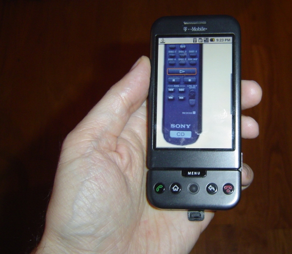
The server can be accessed locally at http://localhost:8080. You may need to mess around with your firewall and router to access it externally; this is left as an exercise for the reader. I found that using my cell phone's browser via Wi-Fi worked surprisingly well, and over the cellular network there was just a slight lag (maybe 1/3 second).
The Arduino code
The code on the Arduino is pretty simple. It reads a command from the serial port and makes the appropriate IR library call. Commands consist of a character indicating the type of code, followed by 8 hex characters. For instance, "S0000004d1" sends the code 4d1 using Sony protocol; this is "play" on my Sony CD player. "N010e03fc" sends 010e03fc using NEC protocol; this turns my Harman Kardon stereo on. The full code is here, but some highlights:
void processSerialCode() {
  if (Serial.available() < 9) return;
  char type = Serial.read();
  unsigned long code = 0;
  // Read 8 hex characters into code (omitted)
  if (type == 'N') {
    irsend.sendNEC(code, 32);
  }
  else if (type == 'S') {
    // Send Sony code 3 times
    irsend.sendSony(code, 12);
    delay(50);
    irsend.sendSony(code, 12);
    delay(50);
    irsend.sendSony(code, 12);
  }
  // More code for RC5 and RC6
}
In more detail, the Arduino waits for 9 characters to be available on the serial port. It then parses the hex value and calls the appropriate IR library send routine. The Arduino code does some special-case stuff for the different code types. Sony codes are transmitted three times as the protocol requires. The RC5 and RC6 protocol uses a toggle bit that is flipped on each transmission. (Disclaimer: I don't have RC5/RC6 devices, so this code is untested.) If your device uses a different protocol that the library doesn't support, you're out of luck unless you add the protocol to the library. That's probably not too hard; a couple people have already implemented new protocols.
The web page
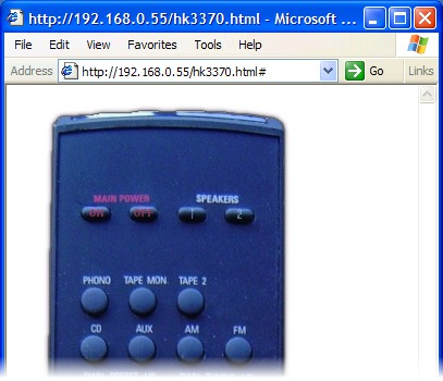
Most of the smarts of the system are in the web page. In my setup, I have a HK-3370 stereo, and a Sony CDP-CE335 CD player. I took a picture of the remote for each and used an HTML image map to make each button clickable. Clicking on a button uses Ajax to POST the appropriate IR code to the server.I use Ajax to send the code to the server to avoid reloading the web page on every click. The Javascript code is verbose but straightforward. The first part of the code creates the XML request object; unfortunately different browsers use different objects. The next part of the code creates and sends the POST request. The actual data sent to the server is, for instance, "code=N12345678" to send 0x12345678 using NEC protocol.
function button(value) {
  if (window.XMLHttpRequest) {
   request = new XMLHttpRequest();
  } else if (window.ActiveXObject) {
    try {
      request = new ActiveXObject("Msxml2.XMLHTTP");
    } catch (e) {
      try {
        request = new ActiveXObject("Microsoft.XMLHTTP");
      } catch (e) {}
    }
  }
  request.open('POST', '/arduino', true);
  request.setRequestHeader('Content-type', 'application/x-www-form-urlencoded');
  request.setRequestHeader('Content-length', value.length);
  request.setRequestHeader('Connection', 'close');
  request.send('code=' + value);
}
The clickable buttons are defined in the HTML through an image and an image map. Generating the image and the image map is the hard part of the whole project:
<img src="hk3370.png" width="268" height="800" border="0" usemap="#map" />
<map name="map">
<area shape="rect" coords="60,97,85,111" href="#" alt="on" onClick="button('N010e03fc')" />
<area shape="rect" coords="104,98,129,109" href="#" alt="off" onClick="button('N010ef906')" />
...
Each line in the map defines a region of the image as a button with a particular code. When clicked, this region will call the button function with the appropriate code, causing the code to be sent to the web server, the Arduino, and finally to the stereo. The alt text isn't actually used, but I recommend it to keep track of what button is associated with each line. The href causes the cursor to change when you go over the region, but isn't necessary.
In this approach, the Arduino code and web server code are very simple, as they don't need to know the functions of the codes. A different way to implement this system would be to put the table of codes ("SONY_CD_ON" = 4d1, etc.) either in the web server code or the Arduino code.
To generate the web pages, I took a picture of the remote with my camera and cleaned up the picture with GIMP. I used the GIMP image map plugin to create the image map. I outlined each button, then filled in the URL with the appropriate IR code, and filled in the alt text with the name of the button. Finally, I copied the map file into the HTML file and edited it to use the Javascript function.
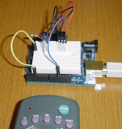
The easiest way to obtain the IR codes is to use the IRrecvDump example sketch included in my IR library. Simply press the button on your remote, see what code was sent, and put that code into the image map. Alternatively, you may be able to find codes in the LIRC database.
Once you get going, it's actually fairly quick to generate the image map. Select a button in the editor, click the physical button on the remote, copy the displayed value into the editor, and move on to the next button. As long as you don't get obsessive and start tweaking the regions to line up perfectly, it's pretty quick.
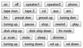
If you don't want to mess around with the image map, take a look at simple.html. This file shows how to use standard HTML buttons. Not as cool as the image, but much easier:
<input type="button" value="on" onClick="button('N010e03fc')" >
<input type="button" value="off" onClick="button('N010ef906')" >
...
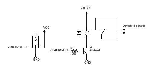
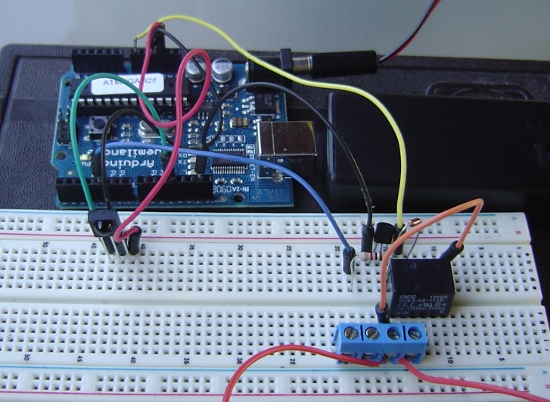
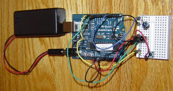
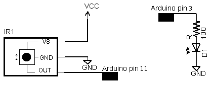
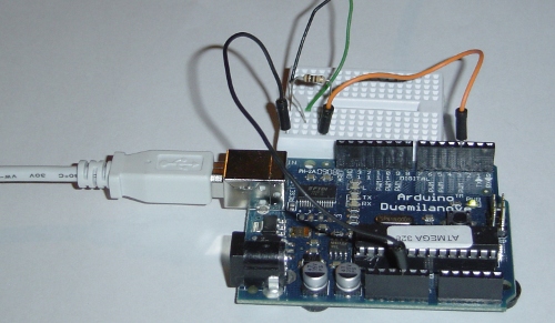
The hardware
The Arduino does the work of converting the hex code into an IR signal. The IR library uses digital PWM pin 3 as output, which must be connected to your IR emitter. I use a 100 ohm resistor to limit current. Wiring it up is trivial.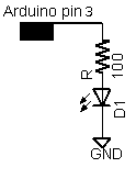
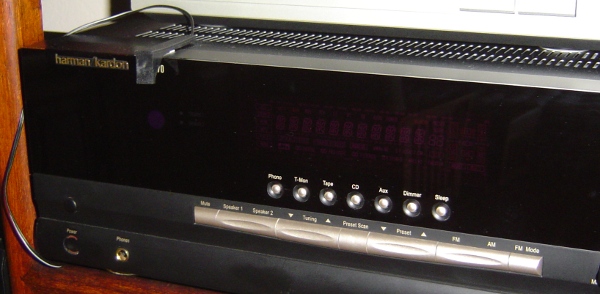
I used a Tivo IR blaster that I had lying around, but a plain IR LED will work too. The following picture shows an IR blaster attached to my sterero. Note that the blaster needs to be positioned about the stereo's IR receiver; it may be easier to see the receiver with a flashlight.
Putting it all together
To summarize the steps:- Download the files and unpack them.
- Get the infrared library and install it.
- Aim the IR source at the device(s) to control, and connect it to the Arduino. (You may want to use a visible LED for testing.)
- Connect the Arduino to the computer's USB port.
- Compile and install
IRwebremote.pdeusing the Arduino IDE. - Create HTML files for your remote controls. (This is the hard step.)
- Run the Python server:
python server.py - Go to
http://localhost:8080and control the devices.