Showing posts with label teardown. Show all posts

Inside the mechanical Bendix Air Data Computer, part 5: motor/tachometers

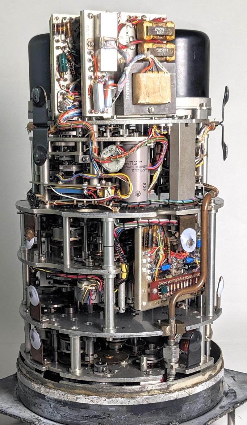
The Bendix Central Air Data Computer (CADC) is an electromechanical analog computer that uses gears and cams for its mathematics. It was a key part of military planes such as the F-101 and the F-111 fighters, computing airspeed, Mach number, and other "air data". The rotating gears are powered by six small servomotors, so these motors are in a sense the fundamental component of the CADC. In the photo below, you can see one of the cylindrical motors near the center, about 1/3 of the way down.

The servomotors in the CADC are unlike standard motors. Their name—"Motor-Tachometer Generator" or "Motor and Rate Generator"1—indicates that each unit contains both a motor and a speed sensor. Because the motor and generator use two-phase signals, there are a total of eight colorful wires coming out, many more than a typical motor. Moreover, the direction of the motor can be controlled, unlike typical AC motors. I couldn't find a satisfactory explanation of how these units worked, so I bought one and disassembled it. This article (part 5 of my series on the CADC2) provides a complete teardown of the motor/generator and explain how it works.

The Bendix MG-1A Central Air Data Computer with the case removed, showing the compact gear mechanisms inside. Click this image (or any other) for a larger version.

The Bendix MG-1A Central Air Data Computer with the case removed, showing the compact gear mechanisms inside. Click this image (or any other) for a larger version.

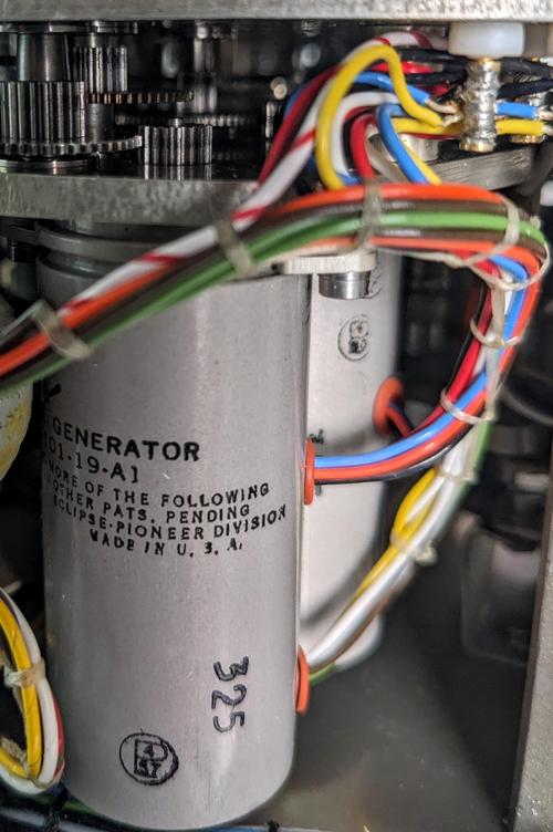
The image below shows a closeup of two motors powering one of the pressure signal outputs. Note the bundles of colorful wires to each motor, entering in two locations. At the top, the motors drive complex gear trains. The high-speed motors are geared down by the gear trains to provide much slower rotations with sufficient torque to power the rest of the CADC's mechanisms.

Two motor/generators in the pressure section of the CADC. The one at the back is mostly hidden.

Two motor/generators in the pressure section of the CADC. The one at the back is mostly hidden.

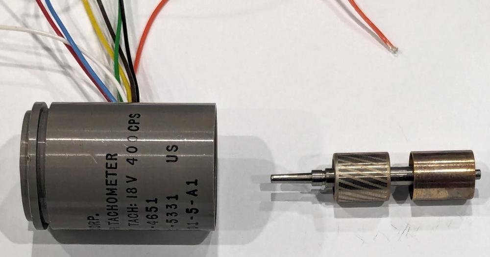
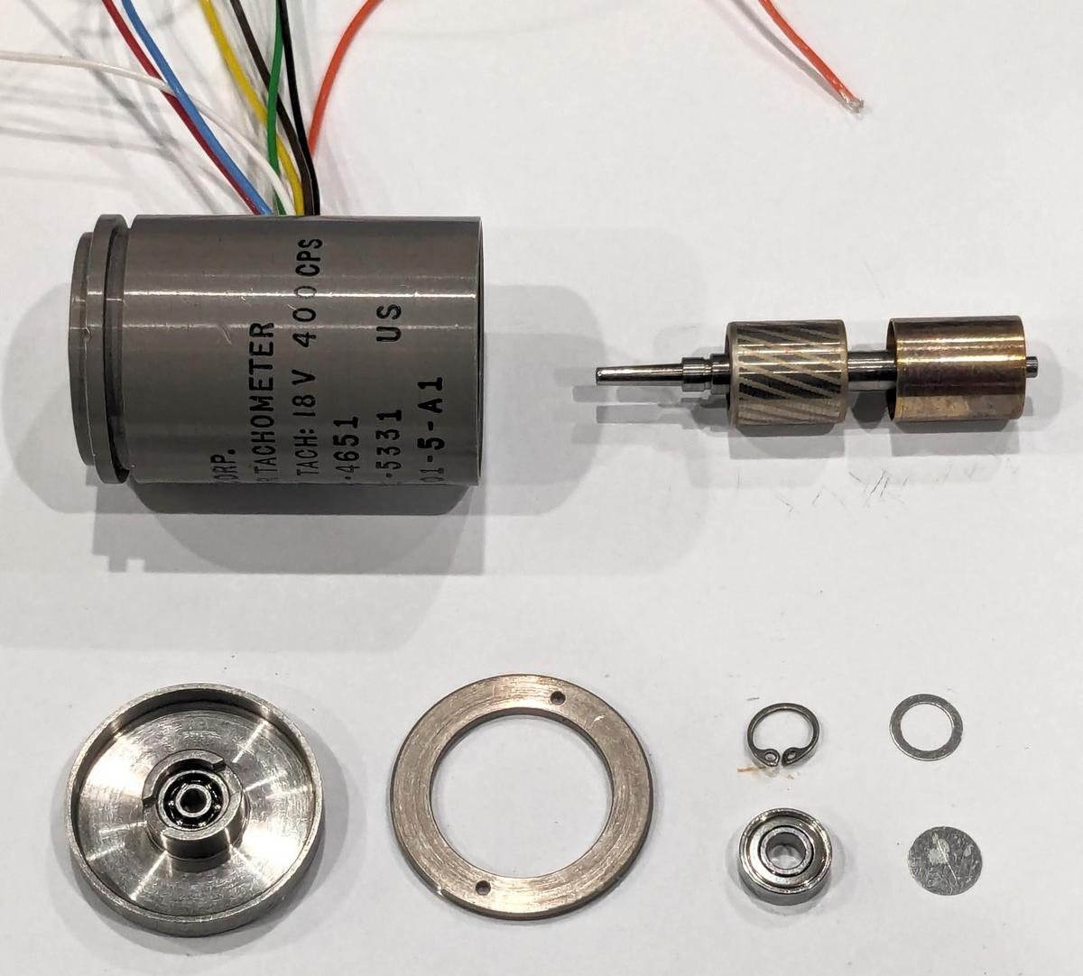
The motor/tachometer that we disassembled is shorter than the ones in the CADC (despite having the same part number), but the principles are the same. We started by removing a small C-clip on the end of the motor and and unscrewing the end plate. The unit is pretty simple mechanically. It has bearings at each end for the rotor shaft. There are four wires for the motor and four wires for the tachometer.3

The motor disassembled to show the internal components.

The motor disassembled to show the internal components.

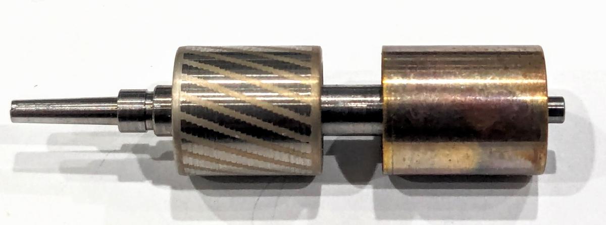
The rotor (below) has two parts on the shaft. the left part is for the motor and the right drum is for the tachometer. The left part is a squirrel-cage rotor4 for the motor. It consists of conducting bars (light-colored) on an iron core. The conductors are all connected at both ends by the conductive rings at either end. The metal drum on the right is used by the tachometer. Note that there are no electrical connections between the rotor components and the rest of the motor: there are no brushes or slip rings. The interaction between the rotor and the windings in the body of the motor is purely magnetic, as will be explained.

The rotor and shaft.

The rotor and shaft.

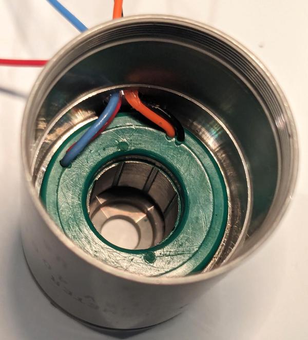
The motor/tachometer contains two cylindrical stators that create the magnetic fields, one for the motor and one for the tachometer. The photo below shows the motor stator inside the unit after removing the tachometer stator. The stators are encased in hard green plastic and tightly pressed inside the unit. In the center, eight metal poles are visible. They direct the magnetic field onto the rotor.

Inside the motor after removing the tachometer winding.

Inside the motor after removing the tachometer winding.

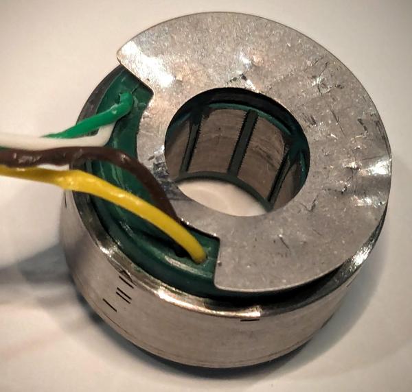
The photo below shows the stator for the tachometer, similar to the stator for the motor. Note the shallow notches that look like black lines in the body on the lower left. These are probably adjustments to the tachometer during manufacturing to compensate for imperfections. The adjustments ensure that the magnetic fields are nulled out so the tachometer returns zero voltage when stationary. The metal plate on top shields the tachometer from the motor's magnetic fields.

The stator for the tachometer.

The stator for the tachometer.

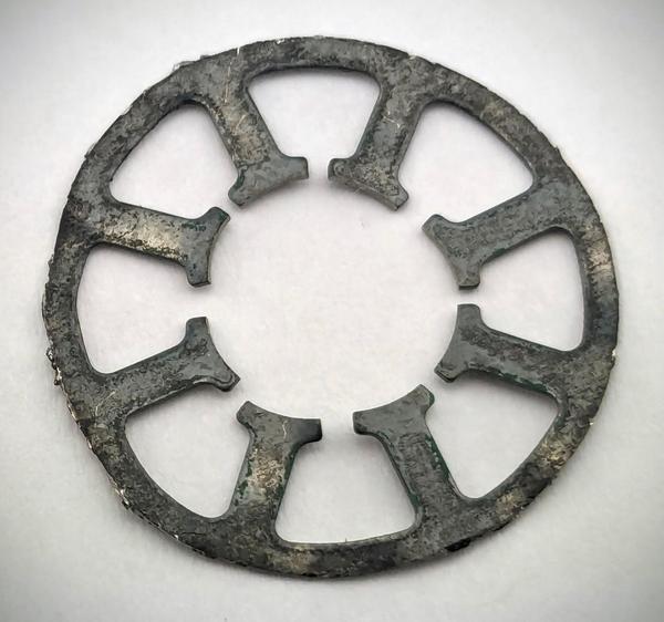
The poles and the metal case of the stator look solid, but they are not. Instead, they are formed from a stack of thin laminations. The reason to use laminations instead of solid metal is to reduce eddy currents in the metal. Each lamination is varnished, so it is insulated from its neighbors, preventing the flow of eddy currents.

One lamination from the stack of laminations that make up the winding. The lamination suffered some damage during disassembly; it was originally round.

One lamination from the stack of laminations that make up the winding. The lamination suffered some damage during disassembly; it was originally round.

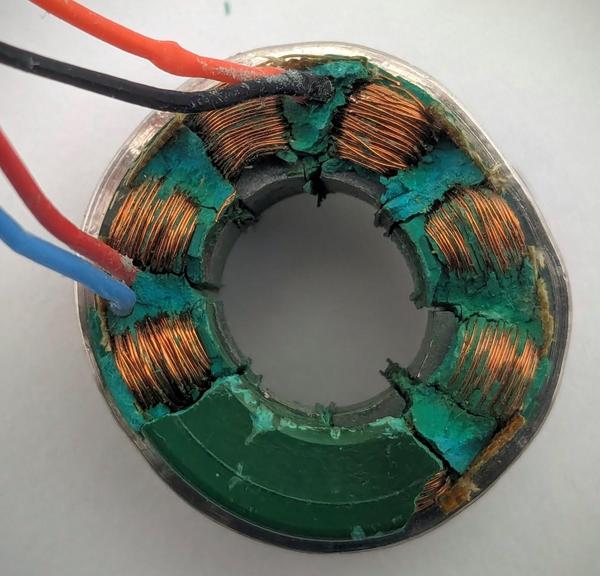
In the photo below, I removed some of the plastic to show the wire windings underneath. The wires look like bare copper, but they have a very thin layer of varnish to insulate them. There are two sets of windings (orange and blue, or red and black) around alternating metal poles. Note that the wires run along the pole, parallel to the rotor, and then wrap around the pole at the top and bottom, forming oblong coils around each pole.5 This generates a magnetic field through each pole.

Removing the plastic reveals the motor windings.

Removing the plastic reveals the motor windings.

The motor

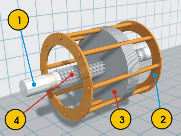
The motor part of the unit is a two-phase induction motor with a squirrel-cage rotor.6 There are no brushes or electrical connections to the rotor, and there are no magnets, so it isn't obvious what makes the rotor rotate. The trick is the "squirrel-cage" rotor, shown below. It consists of metal bars that are connected at the top and bottom by rings. Assume (for now) that the fixed part of the motor, the stator, creates a rotating magnetic field. The important principle is that a changing magnetic field will produce a current in a wire loop.7 As a result, each loop in the squirrel-cage rotor will have an induced current: current will flow up9 the bars facing the north magnetic field and down the south-facing bars, with the rings on the end closing the circuits.

A squirrel-cage rotor. The numbered parts are (1) shaft, (2) end cap, (3) laminations, and (4) splines to hold the laminations. Image from Robo Blazek.

A squirrel-cage rotor. The numbered parts are (1) shaft, (2) end cap, (3) laminations, and (4) splines to hold the laminations. Image from Robo Blazek.

But how does the stator produce a rotating magnetic field? And how do you control the direction of rotation? The next important principle is that current flowing through a wire produces a magnetic field.8 As a result, the currents in the squirrel cage rotor produce a magnetic field perpendicular to the cage. This magnetic field causes the rotor to turn in the same direction as the stator's magnetic field, driving the motor. Because the rotor is powered by the induced currents, the motor is called an induction motor.

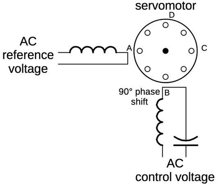
The diagram below shows how the motor is wired, with a control winding and a reference winding. Both windings are powered with AC, but the control voltage either lags the reference winding by 90° or leads the reference winding by 90°, due to the capacitor. Suppose the current through the control winding lags by 90°. First, the reference voltage's sine wave will have a peak, producing the magnetic field's north pole at A. Next (90° later), the control voltage will peak, producing the north pole at B. The reference voltage will go negative, producing a south pole at A and thus a north pole at C. The control voltage will go negative, producing a south pole at B and a north pole at D. This cycle will repeat, with the magnetic field rotating counter-clockwise from A to D. Conversely, if the control voltage leads the reference voltage, the magnetic field will rotate clockwise. This causes the motor to spin in one direction or the other, with the direction controlled by the control voltage. (The motor has four poles for each winding, rather than the one shown below; this increases the torque and reduces the speed.)
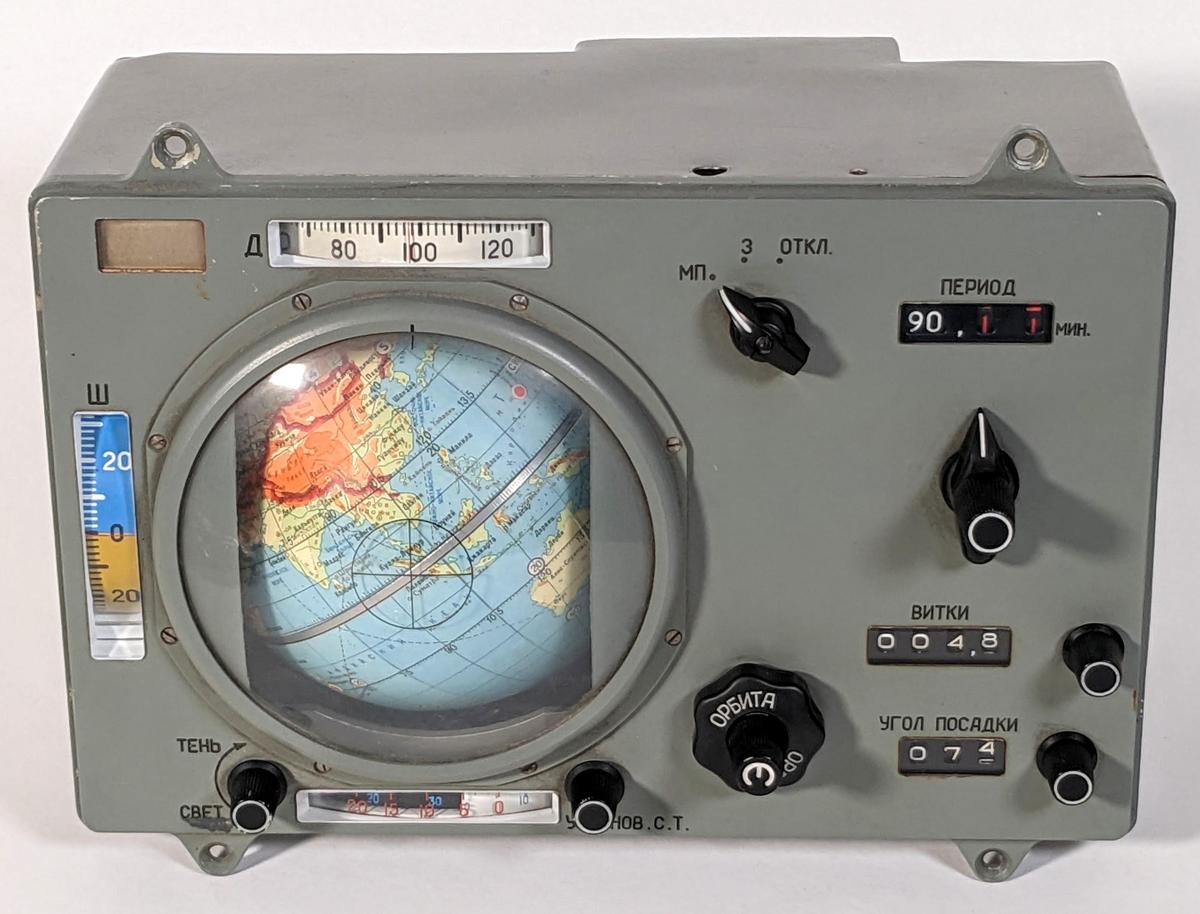
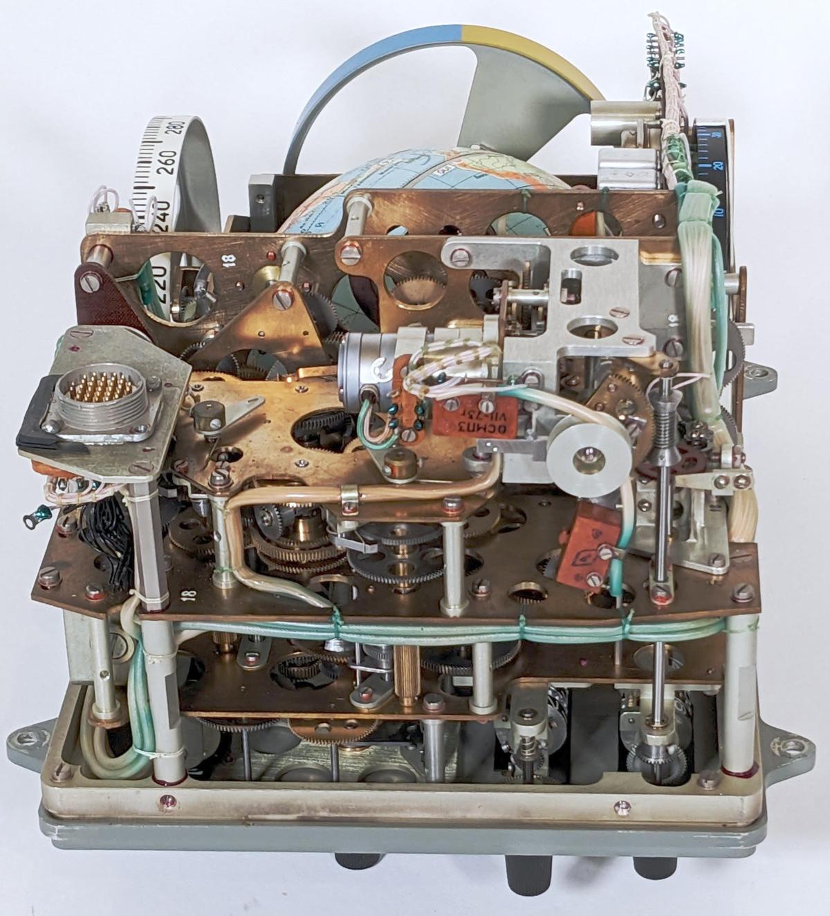
Diagram showing the servomotor wiring.

Diagram showing the servomotor wiring.

The purpose of the capacitor is to provide the 90° phase shift so the reference voltage and the control voltage can be driven from the same single-phase AC supply (in this case, 26 volts, 400 hertz). Switching the polarity of the control voltage reverses the direction of the motor.

There are a few interesting things about induction motors. You might expect that the motor would spin at the same rate as the rotating magnetic field. However, this is not the case. Remember that a changing magnetic field induces the current in the squirrel-cage rotor. If the rotor is spinning at the same rate as the magnetic field, the rotor will encounter an unchanging magnetic field and there will be no current in the bars of the rotor. As a result, the rotor will not generate a magnetic field and there will be no torque to rotate it. The consequence is that the rotor must spin somewhat slower than the magnetic field. This is called "slippage" and is typically a few percent of the full speed, with more slippage as more torque is required.

Many household appliances use induction motors, but how do they generate a rotating magnetic field from a single-phase AC winding? The problem is that the magnetic field in a single AC winding will just flip back and forth, so the motor will not turn in either direction. One solution is a shaded-pole motor, which puts a copper bar around part of each pole to break the symmetry and produce a weakly rotating magnetic field. More powerful induction motors use a startup winding with a capacitor (analogous to the control winding). This winding can either be switched out of the circuit once the motor starts spinning,10 or used continuously, called a permanent-split capacitor (PSC) motor. The best solution is three-phase power (if available); a three-phase winding automatically produces a rotating magnetic field.

Tachometer/generator

The second part of the unit is the tachometer generator, sometimes called the rate unit.11 The purpose of the generator is to produce a voltage proportional to the speed of the shaft. The unusual thing about this generator is that it produces a 400-hertz output that is either in phase with the input or 180° out of phase. This is important because the phase indicates which direction the shaft is turning. Note that a "normal" generator is different: the output frequency is proportional to the speed.

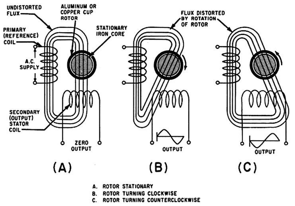
The diagram below shows the principle behind the generator. It has two stator windings: the reference coil that is powered at 400 Hz, and the output coil that produces the output signal. When the rotor is stationary (A), the magnetic flux is perpendicular to the output coil, so no output voltage is produced. But when the rotor turns (B), eddy currents in the rotor distort the magnetic field. It now couples with the output coil, producing a voltage. As the rotor turns faster, the magnetic field is distorted more, increasing the coupling and thus the output voltage. If the rotor turns in the opposite direction (C), the magnetic field couples with the output coil in the opposite direction, inverting the output phase. (This diagram is more conceptual than realistic, with the coils and flux 90° from their real orientation, so don't take it too seriously. As shown earlier, the coils are perpendicular to the rotor so the real flux lines are completely different.)

Principle of the drag-cup rate generator. From Navy electricity and electronics training series: Principles of synchros, servos, and gyros, Fig 2-16

But why does the rotating drum change the magnetic field? It's easier to understand by considering a tachometer that uses a squirrel-cage rotor instead of a drum. When the rotor rotates, currents will be induced in the squirrel cage, as described earlier with the motor. These currents, in turn, generate a perpendicular magnetic field, as before. This magnetic field, perpendicular to the orginal field, will be aligned with the output coil and will be picked up. The strength of the induced field (and thus the output voltage) is proportional to the speed, while the direction of the field depends on the direction of rotation. Because the primary coil is excited at 400 hertz, the currents in the squirrel cage and the resulting magnetic field also oscillate at 400 hertz. Thus, the output is at 400 hertz, regardless of the input speed.

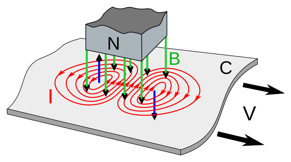
Using a drum instead of a squirrel cage provides higher accuracy because there are no fluctuations due to the discrete bars. The operation is essentially the same, except that the currents pass through the metal of the drum continuously instead of through individual bars. The result is eddy currents in the drum, producing the second magnetic field. The diagram below shows the eddy currents (red lines) from a metal plate moving through a magnetic field (green), producing a second magnetic field (blue arrows). For the rotating drum, the situation is similar except the metal surface is curved, so both field arrows will have a component pointing to the left. This creates the directed magnetic field that produces the output.

A diagram showing eddy currents in a metal plate moving under a magnet, Image from Chetvorno.

A diagram showing eddy currents in a metal plate moving under a magnet, Image from Chetvorno.

The servo loop

The motor/generator is called a servomotor because it is used in a servo loop, a control system that uses feedback to obtain precise positioning. In particular, the CADC uses the rotational position of shafts to represent various values. The servo loops convert the CADC's inputs (static pressure, dynamic pressure, temperature, and pressure correction) into shaft positions. The rotations of these shafts power the gears, cams, and differentials that perform the computations.

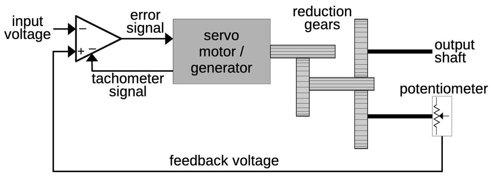
The diagram below shows a typical servo loop in the CADC. The goal is to rotate the output shaft to a position that exactly matches the input voltage. To accomplish this, the output position is converted into a feedback voltage by a potentiometer that rotates as the output shaft rotates.12 The error amplifier compares the input voltage to the feedback voltage and generates an error signal, rotating the servomotor in the appropriate direction. Once the output shaft is in the proper position, the error signal drops to zero and the motor stops. To improve the dynamic response of the servo loop, the tachometer signal is used as a negative feedback voltage. This ensures that the motor slows as the system gets closer to the right position, so the motor doesn't overshoot the position and oscillate. (This is sort of like a PID controller.)

Diagram of a servo loop in the CADC.

Diagram of a servo loop in the CADC.

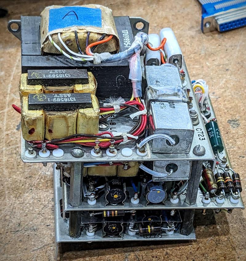
The error amplifier and motor drive circuit for a pressure transducer are shown below. Because of the state of electronics at the time, it took three circuit boards to implement a single servo loop. The amplifier was implemented with germanium transistors (since silicon transistors were later). The transistors weren't powerful enough to drive the motors directly. Instead, magnetic amplifiers (the yellow transformer-like modules at the front) powered the servomotors. The large rectangular capacitors on the right provided the phase shift required for the control voltage.

One of the three-board amplifiers for the pressure transducer.

One of the three-board amplifiers for the pressure transducer.

Conclusions

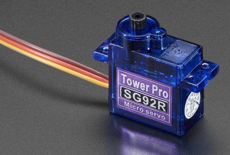
The Bendix CADC used a variety of electromechanical devices including synchros, control transformers, servo motors, and tachometer generators. These were expensive military-grade components driven by complex electronics. Nowadays, you can get a PWM servo motor for a few dollars with the gearing, feedback, and control circuitry inside the motor housing. These motors are widely used for hobbyist robotics, drones, and other applications. It's amazing that servo motors have gone from specialized avionics hardware to an easy-to-use, inexpensive commodity.

A modern DC servo motor. Photo by Adafruit (CC BY-NC-SA 2.0 DEED).

A modern DC servo motor. Photo by Adafruit (CC BY-NC-SA 2.0 DEED).

Follow me on Twitter @kenshirriff or RSS for updates. I'm also on Mastodon as @oldbytes.space@kenshirriff. Thanks to Joe for providing the CADC. Thanks to Marc Verdiell for disassembling the motor.

Notes and references

  1. The two types of motors in the CADC are part number "FV-101-19-A1" and part number "FV-101-5-A1" (or FV101-5A1). They are called either a "Tachometer Rate Generator" or "Tachometer Motor Generator", with both names applied to the same part number. The "19" and "5" units look the same, with the "19" used for one pressure servo loop and the "5" used everywhere else.

    The motor that I got is similar to the ones in the CADC, but shorter. The difference in size is mysterious since both have the Bendix part number FV-101-5-A1.

    For reference, the motor I disassembled is labeled:

    Cedar Division Control Data Corp. ST10162 Motor Tachometer F0: 26V C0: 26V TACH: 18V 400 CPS DSA-400-70C-4651 FSN6105-581-5331 US BENDIX FV-101-5-A1

    I wondered why the motor listed both Control Data and Bendix. In 1952, the Cedar Engineering Company was spun off from the Minneapolis Honeywell Regulator Company (better known as Honeywell, the name it took in 1964). Cedar Engineering produced motors, servos, and aircraft actuators. In 1957, Control Data bought Cedar Engineering, which became the Cedar Division of CDC. Then, Control Data acquired Bendix's computer division in 1963. Thus, three companies were involved. 

  2. My previous articles on the CADC are:


  3. From testing the motor, here is how I believe it is wired:
    Motor reference (power): red and black
    Motor control: blue and orange
    Generator reference (power): green and brown
    Generator out: white and yellow 

  4. The bars on the squirrel-cage rotor are at a slight angle. Parallel bars would go in and out of alignment with the stator, causing fluctuations in the force, while the angled bars avoid this problem. 

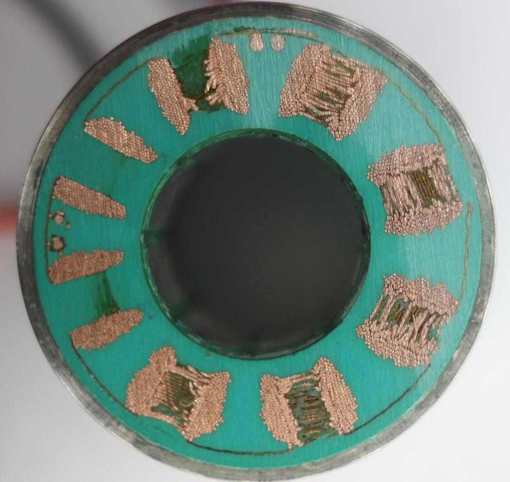
  5. This cross-section through the stator shows the windings. On the left, each winding is separated into the parts on either side of the pole. On the right, you can see how the wires loop over from one side of the pole to the other. Note the small circles in the 12 o'clock and 9 o'clock positions: cross sections of the input wires. The individual horizontal wires near the circumference connect alternating windings.

    A cross-section of the stator, formed by sanding down the plastic on the end.

    A cross-section of the stator, formed by sanding down the plastic on the end.


  6. It's hard to find explanations of AC servomotors since they are an old technology. One discussion is in Electromechanical components for servomechanisms (1961). This book points out some interesting things about a servomotor. The stall torque is proportional to the control voltage. Servomotors are generally high-speed, but low-torque devices, heavily geared down. Because of their high speed and their need to change direction, rotational inertia is a problem. Thus, servomotors typically have a long, narrow rotor compared with typical motors. (You can see in the teardown photo that the rotor is long and narrow.) Servomotors are typically designed with many poles (to reduce speed) and smaller air gaps to increase inductance. These small airgaps (e.g. 0.001") require careful manufacturing tolerance, making servomotors a precision part. 

  7. The principle is Faraday's law of induction: "The electromotive force around a closed path is equal to the negative of the time rate of change of the magnetic flux enclosed by the path." 

  8. Ampère's law states that "the integral of the magnetizing field H around any closed loop is equal to the sum of the current flowing through the loop." 

  9. The direction of the current flow (up or down) depends on the direction of rotation. I'm not going to worry about the specific direction of current flow, magnetic flux, and so forth in this article. 

  10. Once an induction motor is spinning, it can be powered from a single AC phase since the stator is rotating with respect to the magnetic field. This works for the servomotor too. I noticed that once the motor is spinning, it can operate without the control voltage. This isn't the normal way of using the motor, though. 

  11. A long discussion of tachometers is in the book Electromechanical Components for Servomechanisms (1961). The AC induction-generator tachometer is described starting on page 193.

    For a mathematical analysis of the tachometer generator, see Servomechanisms, Section 2, Measurement and Signal Converters, MCP 706-137, U.S. Army. This source also discusses sources of errors in detail. Inexpensive tachometer generators may have an error of 1-2%, while precision devices can have an error of about 0.1%. Accuracy is worse for small airborne generators, though. Since the Bendix CADC uses the tachometer output for damping, not as a signal output, accuracy is less important. 

  12. Different inputs in the CADC use different feedback mechanisms. The temperature servo uses a potentiometer for feedback. The angle of attack correction uses a synchro control transformer, which generates a voltage based on the angle error. The pressure transducers contain inductive pickups that generate a voltage based on the pressure error. For more details, see my article on the CADC's pressure transducer servo circuits

Inside the Globus INK: a mechanical navigation computer for Soviet spaceflight

The Soviet space program used completely different controls and instruments from American spacecraft. One of the most interesting navigation instruments onboard Soyuz spacecraft was the Globus, which used a rotating globe to indicate the spacecraft's position above the Earth. This navigation instrument was an electromechanical analog computer that used an elaborate system of gears, cams, and differentials to compute the spacecraft's position. Officially, the unit was called a "space navigation indicator" with the Russian acronym ИНК (INK),1 but I'll use the more descriptive nickname "Globus".

The INK-2S "Globus" space navigation indicator. Coincidentally, the latitude indicator matches the Ukrainian flag.

The INK-2S "Globus" space navigation indicator. Coincidentally, the latitude indicator matches the Ukrainian flag.

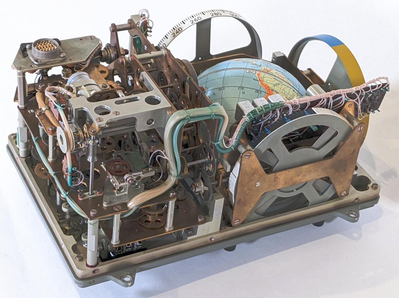
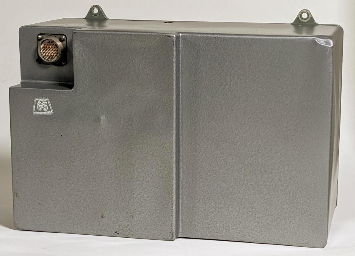
We recently received a Globus from a collector and opened it up for repair and reverse engineering. In this blog post, I explain how it operated, show its internal mechanisms, and describe what I've learned so far from reverse engineering. The photo below gives an idea of the mechanical complexity of this device, which also has a few relays, solenoids, and other electrical components.

Side view of the Globus INK. Click this (or any other image) for a larger version.

Side view of the Globus INK. Click this (or any other image) for a larger version.

Functionality

The primary purpose of the Globus was to indicate the spacecraft's position. The globe rotated while fixed crosshairs on the plastic dome indicated the spacecraft's position. Thus, the globe matched the cosmonauts' view of the Earth, allowing them to confirm their location. Latitude and longitude dials next to the globe provided a numerical indication of location. Meanwhile, a light/shadow dial at the bottom showed when the spacecraft would be illuminated by the sun or in shadow, important information for docking. The Globus also had an orbit counter, indicating the number of orbits.

The Globus had a second mode, indicating where the spacecraft would land if they fired the retrorockets to initiate a landing. Flipping a switch caused the globe to rotate until the landing position was under the crosshairs and the cosmonauts could evaluate the suitability of this landing site.

The cosmonauts configured the Globus by turning knobs to set the spacecraft's initial position and orbital period. From there, the Globus electromechanically tracked the orbit. Unlike the Apollo Guidance Computer, the Globus did not receive navigational information from an inertial measurement unit (IMU) or other sources, so it did not know the spacecraft's real position. It was purely a display of the predicted position.

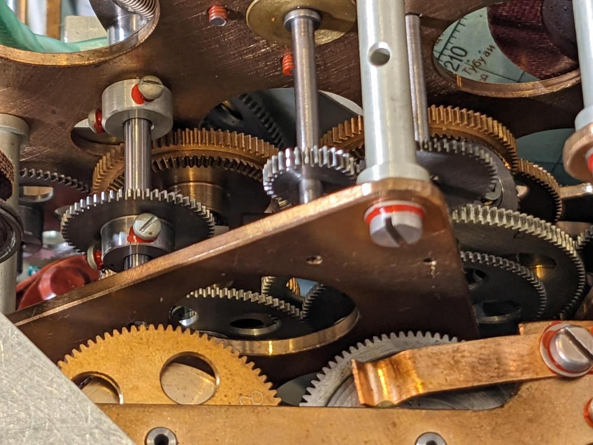
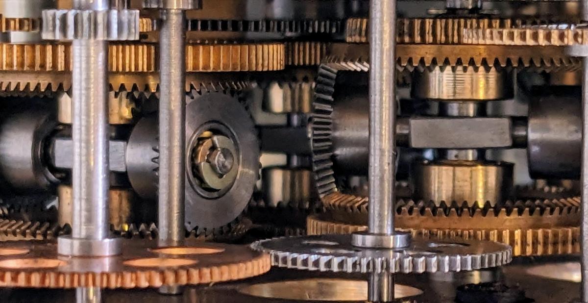
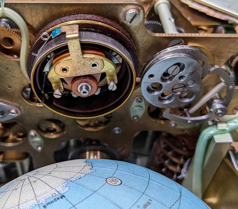
A close-up of the complex gear trains in the Globus.

A close-up of the complex gear trains in the Globus.

The globe

The globe itself is detailed for its small size, showing terrain features such as mountains, lakes, and rivers. These features on the map helped cosmonauts compare their position with the geographic features they could see on Earth. These features were also important for selecting a landing site, so they could see what kind of terrain they would be landing on. For the most part, the map doesn't show political boundaries, except for thick red and purple lines. This line shows the borders of the USSR, as well as the boundaries between communist and non-communist countries, also important for selecting a landing site. The globe also has numbered circles 1 through 8 that indicate radio sites for communication with the spacecraft, allowing the cosmonauts to determine what ground stations could be contacted.

A view of the globe showing Asia.

A view of the globe showing Asia.

Controlling the globe

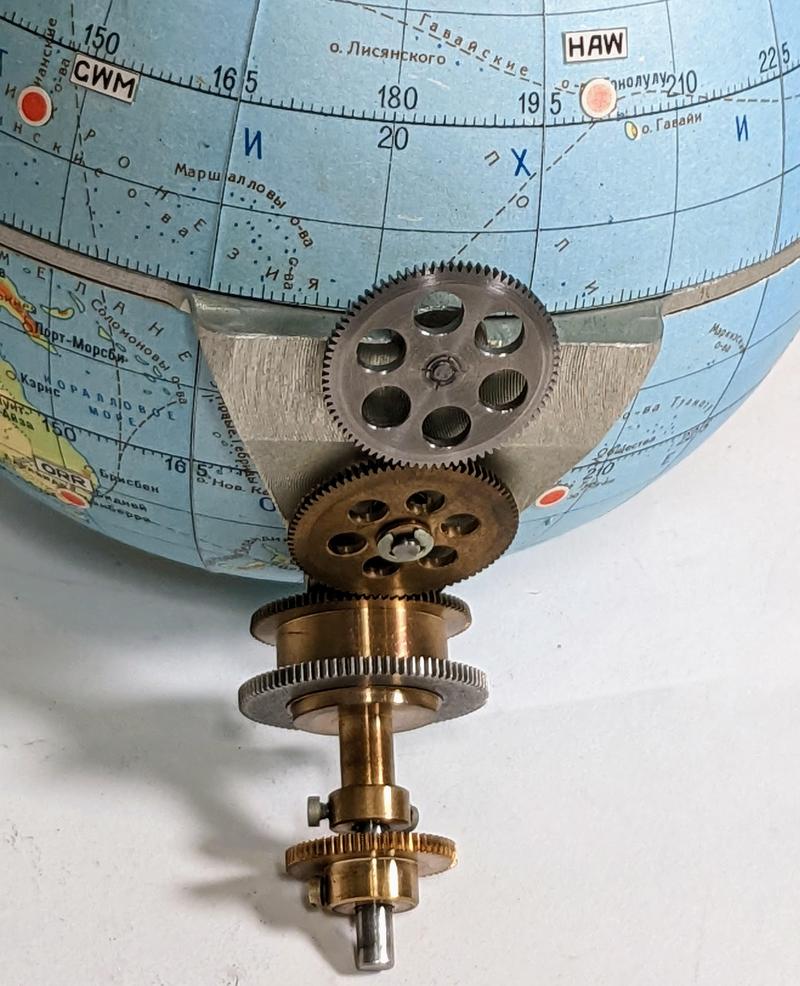
On seeing the Globus, one might wonder how the globe is rotated. It may seem that the globe must be free-floating so it can rotate in two axes. Instead, a clever mechanism attaches the globe to the unit. The key is that the globe's equator is a solid piece of metal that rotates around the horizontal axis of the unit. A second gear mechanism inside the globe rotates the globe around the North-South axis. The two rotations are controlled by concentric shafts that are fixed to the unit, allowing two rotational degrees of freedom through fixed shafts.

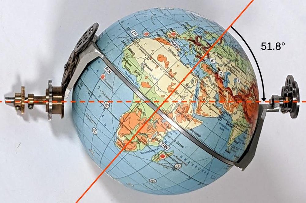
The photo below shows the frame that holds and controls the globe. The dotted axis is fixed horizontally in the unit and rotations are fed through the two gears at the left. One gear rotates the globe and frame around the dotted axis, while the gear train causes the globe to rotate around the vertical polar axis (while the equator remains fixed).

The axis of the globe is at 51.8° to support that orbital inclination.

The axis of the globe is at 51.8° to support that orbital inclination.

The angle above is 51.8° which is very important: this is the inclination of the standard Soyuz orbit. As a result, simply rotating the globe around the dotted line causes the crosshair to trace the standard orbit.2 Rotating the two halves of the globe around the poles yields the different 51.8° orbits over the Earth's surface as the Earth rotates. (Why 51.8 degrees? The Baikonur Cosmodrome, launching point for Soyuz, is at 45.97° N latitude, so 45.97° would be the most efficient inclination. However, to prevent the launch from passing over western China, the rocket must be angled towards the north, resulting in 51.8° (details).)

One important consequence of this design is that the orbital inclination is fixed by the angle of the globe mechanism. Different Globus units needed to be built for different orbits. Moreover, this design only handles circular orbits, making it useless during orbit changes such as rendezvous and docking. These were such significant limitations that some cosmonauts wanted the Globus removed from the control panel, but it remained until it was replaced by a computer display in Soyuz-TMA (2002).3

A closeup of the gears that drive the motion of the two halves of the globe around the polar axis, leaving the equator fixed.

A closeup of the gears that drive the motion of the two halves of the globe around the polar axis, leaving the equator fixed.

This Globus had clearly suffered some damage. The back of the case had some large dents.7 More importantly, the globe's shaft had been knocked loose from its proper position and no longer meshed with the gears. This also put a gouge into Africa, where the globe hit internal components. Fortunately, CuriousMarc was able to get the globe back into position while ensuring that the gears had the right timing. (Putting the globe back arbitrarily would mess up the latitude and longitude.)

Orbital speed and the "cone"

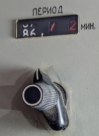
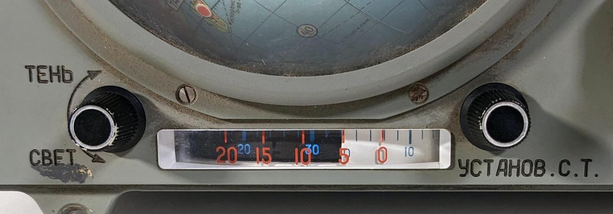
An orbit of Soyuz takes approximately 90 minutes, but the time varies according to altitude.4 The Globus has an adjustment knob (below) to adjust the orbital period in minutes, tenths of minutes, and hundredths of minutes. The outer knob has three positions and points to the digit that changes when the inner knob is turned. The mechanism provides an adjustment of ±5 minutes from the nominal period of 91.85 minutes.3

The control to adjust the orbital period.

The control to adjust the orbital period.

The orbital speed feature is implemented by increasing or decreasing the speed at which the globe rotates around the orbital (horizontal) axis. Generating a variable speed is tricky, since the Globus runs on fixed 1-hertz pulses. The solution is to start with a base speed, and then add three increments: one for the minutes setting, one for the tenths-of-minutes setting, and one for the hundredths-of-minutes setting.5 These four speeds are added (as shaft rotation speeds) using obtain the overall rotation speed.

The Globus uses numerous differential gears to add or subtract rotations. The photo below shows two sets of differential gears, side-by-side.

Two differential gears in the Globus.

Two differential gears in the Globus.

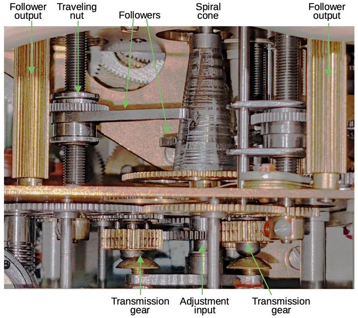
The problem is how to generate these three variable rotation speeds from the fixed input. The solution is a special cam, shaped like a cone with a spiral cross-section. Three followers ride on the cam, so as the cam rotates, the follower is pushed outward and rotates on its shaft. If the follower is near the narrow part of the cam, it moves over a small distance and has a small rotation. But if the follower is near the wide part of the cam, it moves a larger distance and has a larger rotation. Thus, by moving the follower to a particular point on the cam, the rotational speed of the follower is selected.

A diagram showing the orbital speed control mechanism. The cone has three followers, but only two are visible from this angle. The "transmission" gears are moved in and out by the outer knob to select which follower is adjusted by the inner knob.

A diagram showing the orbital speed control mechanism. The cone has three followers, but only two are visible from this angle. The "transmission" gears are moved in and out by the outer knob to select which follower is adjusted by the inner knob.

Obviously, the cam can't spiral out forever. Instead, at the end of one revolution, its cross-section drops back sharply to the starting diameter. This causes the follower to snap back to its original position. To prevent this from jerking the globe backward, the follower is connected to the differential gearing via a slip clutch and ratchet. Thus, when the follower snaps back, the ratchet holds the drive shaft stationary. The drive shaft then continues its rotation as the follower starts cycling out again. Thus, the output is a (mostly) smooth rotation at a speed that depends on the position of the follower.

Latitude and longitude

The indicators at the left and the top of the globe indicate the spacecraft's latitude and longitude respectively. These are defined by surprisingly complex functions, generated by the orbit's projection onto the globe.6

The latitude and longitude functions are implemented through the shape of metal cams; the photo below shows the longitude mechanism. Each function has two cams: one cam implements the desired function, while the other cam has the "opposite" shape to maintain tension on the jaw-like tracking mechanism.

The cam mechanism to compute longitude.

The cam mechanism to compute longitude.

The latitude cam drives the latitude dial, causing it to oscillate between 51.8° N and 51.8° S. Longitude is more complicated because the Earth's rotation causes it to constantly vary. The longitude output on the dial is produced by adding the cam's value to the Earth's rotation through a differential gear.

Light and shadow

The Globus has an indicator to show when the spacecraft will enter light or shadow. The dial consists of two concentric dials, configured by the two knobs. These dials move with the spacecraft's orbit, while the red legend remains fixed. I think these dials are geared to the longitude dial, but I'm still investigating.

The light and shadow indicator is controlled by two knobs.

The light and shadow indicator is controlled by two knobs.

The landing location mechanism

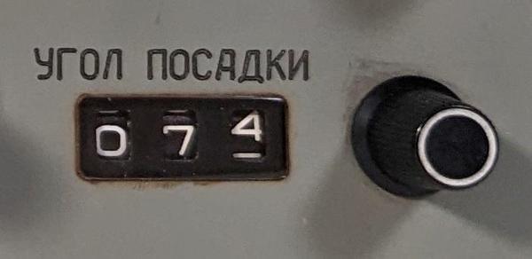
The Globus can display where the spacecraft would land if you started a re-entry burn now, with an accuracy of 150 km. This is computed by projecting the current orbit forward by a partial orbit, depending on how long it would take to land. The cosmonaut specifies this value by the "landing angle", which indicates this fraction of an orbit as an angle. An electroluminescent indicator in the upper-left corner of the unit shows "Место посадки" (Landing place) to indicate this mode.

The landing angle control.

The landing angle control.

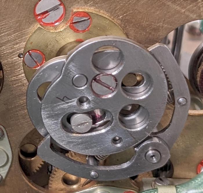
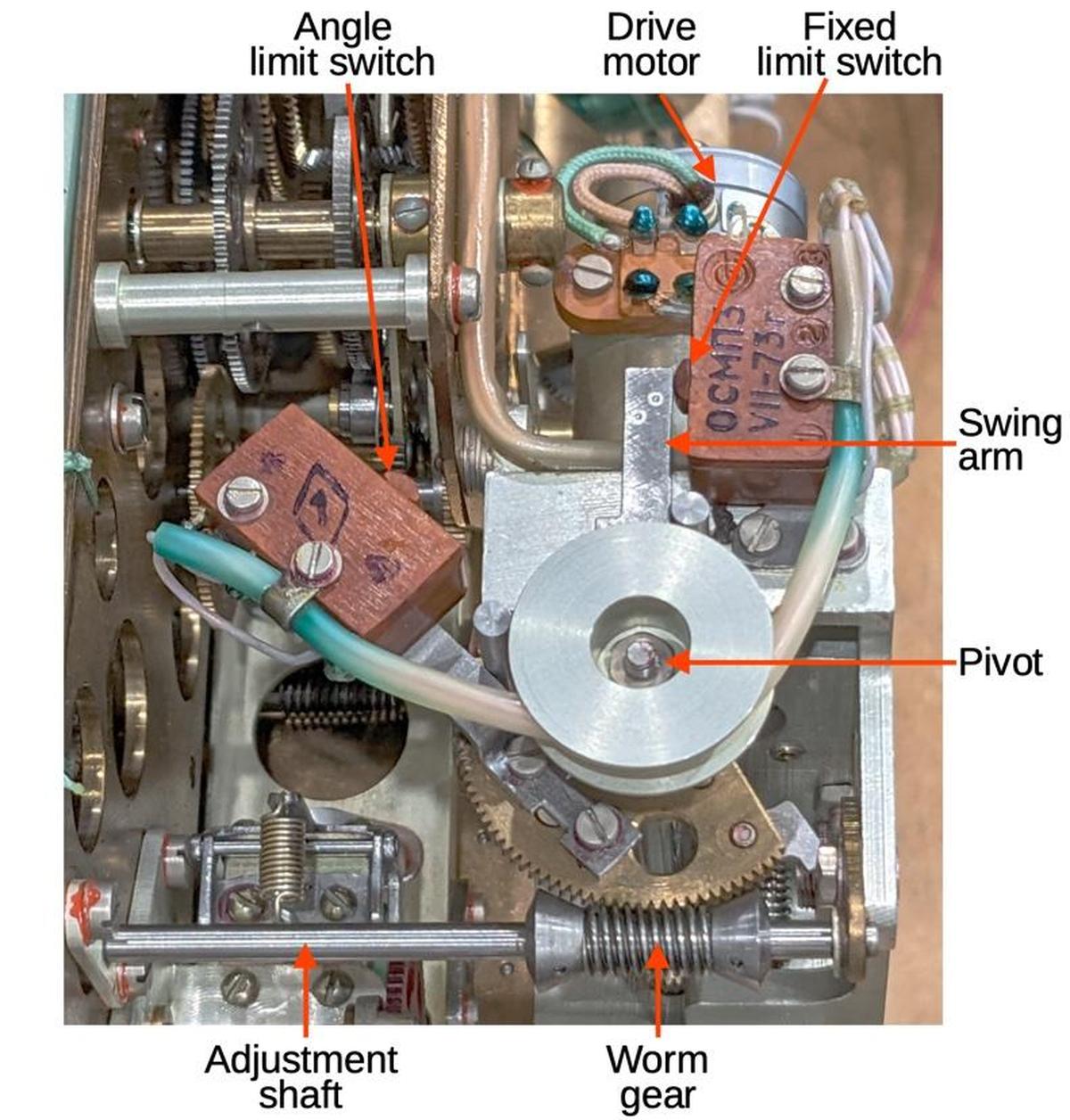
To obtain the landing position, a motor spins the globe until it is stopped after rotating through the specified angle. The mechanism to implement this is shown below. The adjustment knob on the panel turns the adjustment shaft which moves the limit switch to the desired angle via the worm gear. The wiring is wrapped around a wheel so the wiring stays controlled during this movement. When the drive motor is activated, it rotates the globe and the swing arm at the same time. Since the motor stops when the swing arm hits the angle limit switch, the globe rotates through the desired angle. The fixed limit switch is used when returning the globe's position to its regular, orbital position.

The landing angle function uses a complex mechanism.

The landing angle function uses a complex mechanism.

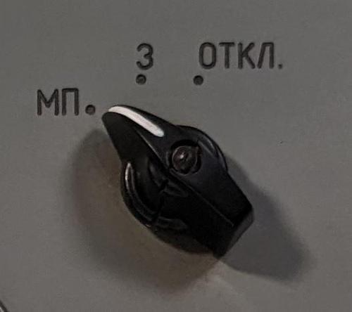
The landing location mode is activated by a three-position rotary switch. The first position "МП" (место посадки, landing site) selects the landing site, the second position "З" (Земля, Earth) shows the position over the Earth, and the third position "Откл" (off) undoes the landing angle rotation and turns off the mechanism.

The rotary switch to select the landing angle mode.

The rotary switch to select the landing angle mode.

Electronics

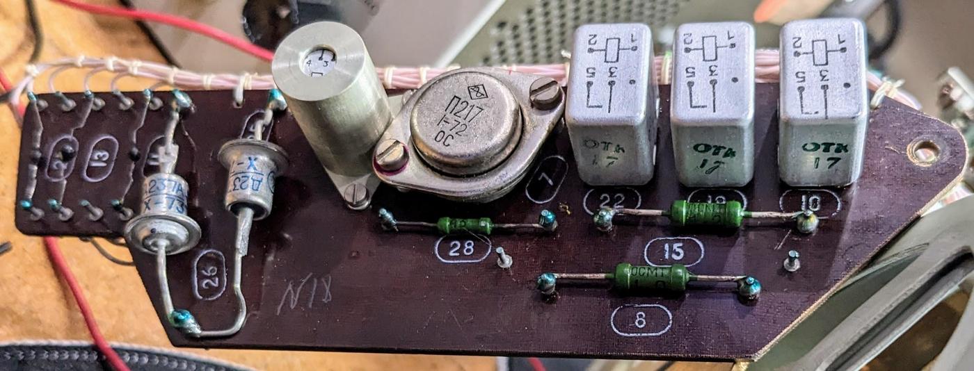
Although the Globus is mostly mechanical, it has an electronics board with four relays and a transistor, as well as resistors and diodes. I think that most of these relays control the landing location mechanism, driving the motor forward or backward and stopping at the limit switch. The diodes are flyback diodes, two diodes in series across each relay coil to eliminate the inductive kick when the coil is disconnected.

The electronics circuit board.

The electronics circuit board.

A 360° potentiometer (below) converts the spacecraft's orbital position into a voltage. Sources indicate that the Globus provides this voltage signal to other units on the spacecraft. My theory is that the transistor on the electronics board amplifies this voltage, but I am still investigating.

The potentiometer converts the orbital position into a voltage.
To the right is the cam that produces the longitude display. Antarctica is visible on the globe.

The potentiometer converts the orbital position into a voltage. To the right is the cam that produces the longitude display. Antarctica is visible on the globe.

The photo below shows the multiple wiring bundles in the Globus, at the front and the left. The electronics board is at the front right. The Globus contains a surprising amount of wiring for a device that is mostly mechanical. Inconveniently, all the wires to the box's external connector (upper left) were cut.7 Perhaps this was part of decommissioning the unit. However, one of the screws on the case is covered with a tamper-resistant wax seal with insignia, and this wax seal was intact. This indicates that the unit was officially re-sealed after cutting the wires, which doesn't make sense for a decommissioned unit.

This view shows the back and underside of the Globus. The round connector at the back left provided the interface with the rest of the spacecraft. The black wires under this connector were all cut.

This view shows the back and underside of the Globus. The round connector at the back left provided the interface with the rest of the spacecraft. The black wires under this connector were all cut.

The drive solenoids

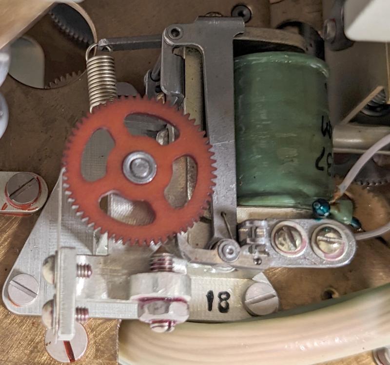
The unit is driven by two ratchet solenoids: one for the orbital rotation and one for the Earth's rotation. These solenoids take 27-volt pulses at 1 hertz.3 Each pulse causes the solenoid to advance the gear by one tooth; a pawl keeps the gear from slipping back. These small rotations drive the gears throughout the Globus and result in a tiny movement of the globe.

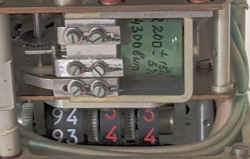
One of the driving solenoids in the Globus. The wheels to indicate orbital time are underneath.

One of the driving solenoids in the Globus. The wheels to indicate orbital time are underneath.

The other driving solenoid in the Globus.

The other driving solenoid in the Globus.

Apollo-Soyuz

If you look closely at the globe, it has a bunch of pink dots added, along with three-letter labels in Latin (not Cyrillic) characters.8 In the photo below, you can see GDS (Goldstone), MIL (Merritt Island), BDA (Bermuda), and NFL (Newfoundland). These are NASA tracking sites, which implies that this Globus was built for the Apollo-Soyuz Test Project, a 1975 mission where an Apollo spacecraft docked with a Soyuz capsule.

North America as it appears on the globe. The US border is marked in red. The selection of cities seems a bit random, such as El Paso as the only western city until the coast.

North America as it appears on the globe. The US border is marked in red. The selection of cities seems a bit random, such as El Paso as the only western city until the coast.

Further confirmation of the Apollo-Soyuz connection is the VAN sticker in the middle of the Pacific Ocean (not visible above). The USNS Vanguard was a NASA tracking ship that was used in the Apollo program to fill in gaps in radio coverage. It was an oil tanker from World War II, converted postwar to a missile tracking ship and then used for Apollo. In the photo below, you can see the large tracking antennas on its deck. During the Apollo-Soyuz mission, Vanguard was stationed at 25 S 155 W for the Apollo-Soyuz mission, exactly matching the location of the VAN dot on the globe.

The USNS Vanguard with a NASA C-54 plane overhead. (source).

The USNS Vanguard with a NASA C-54 plane overhead. (source).

History

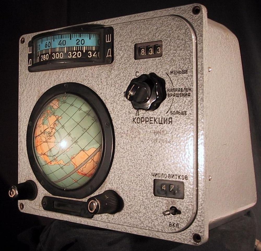
The Globus has a long history, back to the beginnings of Soviet crewed spaceflight. The first version was simpler and had the Russian acronym ИМП (IMP).9 Development of the IMP started in 1960 for the Vostok (1961) and Voshod (1964) spaceflights.

The Globus IMP. Photo from Francoisguay (CC BY-SA 3.0).

The Globus IMP. Photo from Francoisguay (CC BY-SA 3.0).

The basic functions of the earlier Globus IMP are similar to the INK, showing the spacecraft's position and the landing position. It has an orbit counter in the lower right. The latitude and longitude displays at the top were added for the Voshod flights. The large correction knob allows the orbital period to be adjusted. The main differences are that the IMP doesn't have a display at the bottom for sun and shade and doesn't have a control to set the landing angle.9 Unlike the INK, the mode (orbit vs landing position) was selected by external switches, rather than a switch on the unit.

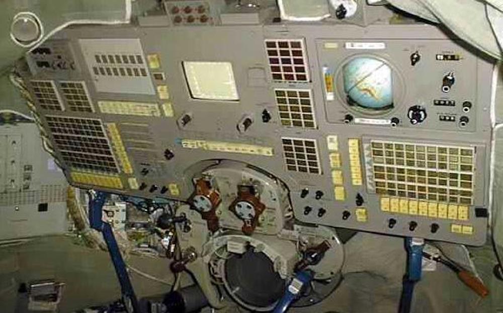
The more complex INK model (described in this blog post) was created for the Soyuz flights, starting in 1967. It was part of the "Sirius" information display system (IDS). The Neptun IDS used on Soyuz-T (1976) and the Neptun-M for Soyuz-TM (1986) modernized much of the console but kept the Globus INK. The photo below shows the Globus mounted in the upper-right of a Soyuz-TM console.

The Neptun-M IDS for the Soyuz-TM (source).

The Neptun-M IDS for the Soyuz-TM (source).

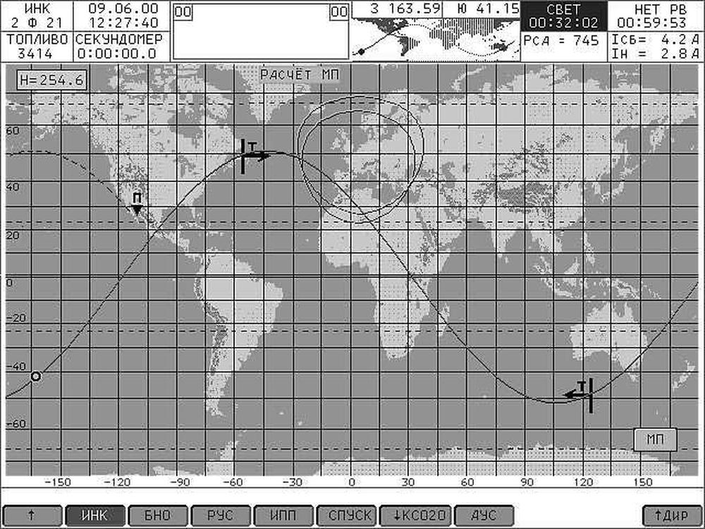
The Soyuz-TMA (2002) upgraded to the Neptun-ME system3 which used digital display screens. In particular, the Globus was replaced with the graphical display below.

A computer display from the Neptune-ME display system used in the Soyuz-TMA spaceship. The Soyuz consoles are much simpler than the Apollo or Space Shuttle consoles, and built with completely different design principles. From Information Display Systems for Soyuz Spaceships.

A computer display from the Neptune-ME display system used in the Soyuz-TMA spaceship. The Soyuz consoles are much simpler than the Apollo or Space Shuttle consoles, and built with completely different design principles. From Information Display Systems for Soyuz Spaceships.

Conclusions

The Globus INK is a remarkable piece of machinery, an analog computer that calculates orbits through an intricate system of gears, cams, and differentials. It provided cosmonauts with a high-resolution, full-color display of the spacecraft's position, way beyond what an electronic space computer could provide in the 1960s.

Although the Globus is an amazing piece of mechanical computation, its functionality is limited. Its parameters must be manually configured: the spacecraft's starting position, the orbital speed, the light/shadow regions, and the landing angle. It doesn't take any external guidance inputs, such as an IMU (inertial measurement unit), so it's not particularly accurate. Finally, it only supports a circular orbit at a fixed angle. While the more modern digital display lacks the physical charm of a rotating globe, the digital solution provides much more capability.

I plan to continue reverse-engineering the Globus and hope to get it operational, so follow me on Twitter @kenshirriff or RSS for updates. I've also started experimenting with Mastodon recently as @oldbytes.space@kenshirriff. Many thanks to Marcel for providing the Globus. Thanks to Stack Overflow for orbit information and my Twitter followers for translation assistance.

I should give a disclaimer that I am still reverse-engineering the Globus, so what I described is subject to change. Also, I don't read Russian, so any errors are the fault of Google Translate. :-)

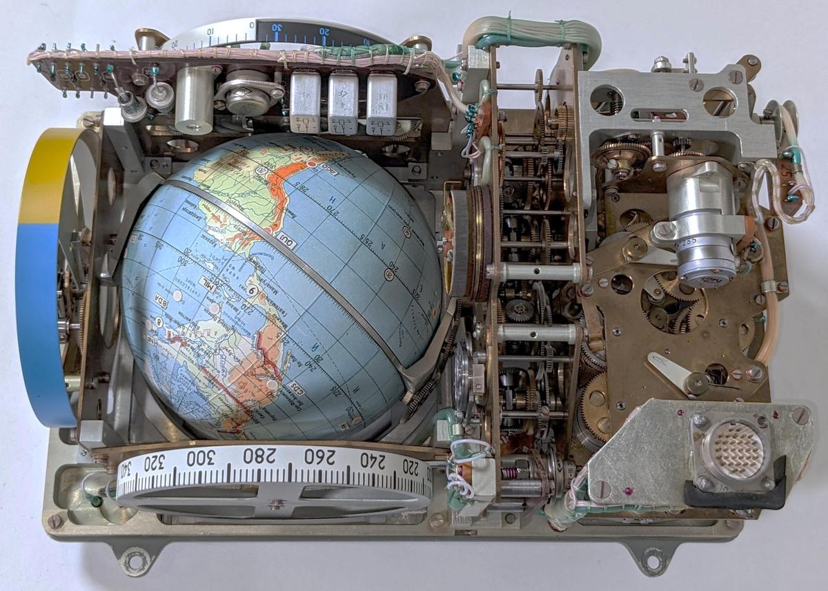
With the case removed, the complex internals of the Globus are visible.

With the case removed, the complex internals of the Globus are visible.

Notes and references

  1. In Russian, the name for the device is "Индикатор Навигационный Космический" abbreviated as ИНК (INK). This translates to "space navigation indicator." The name Globus (Глобус) seems to be a nickname, and I suspect it's more commonly used in English than Russian. 

  2. To see how the angle between the poles and the globe's rotation results in the desired orbital inclination, consider two limit cases. First, suppose the angle between is 90°. In this case, the globe is "straight" with the equator horizontal. Rotating the globe along the horizontal axis, flipping the poles end-over-end, will cause the crosshair to trace a polar orbit, giving the expected inclination of 90°. On the other hand, suppose the angle is 0°. In this case, the globe is "sideways" with the equator vertical. Rotating the globe will cause the crosshair to remain over the equator, corresponding to an equatorial orbit with 0° inclination. 

  3. A detailed description of Globus in Russian is in this document, in Section 5. 

  4. Or conversely, the altitude varies according to the speed. 

  5. Note that panel control adjusts the period of the orbit, while the implementation adjusts the speed of the orbit. These are reciprocals, so linear changes in the period result in hyperbolic changes in the speed. The mechanism, however, changes the speed linearly, which seems like it wouldn't work. However, since the period is large relative to the change in the period, this linear approximation works and the error is small, about 1%. It's possible that the cone has a nonlinear shape to correct this, but I couldn't detect any nonlinearity in photographs. 

  6. The latitude is given by arcsin(sin i * sin (2πt/T)), while the longitude is given by λ = arctan (cos i * tan(2πt/T)) + Ωt + λ0, where t is the spaceship's flight time starting at the equator, i is the angle of inclination (51.8°), T is the orbital period, Ω is the angular velocity of the Earth's rotation, and λ0 is the longitude of the ascending node.3

    The formula for latitude is simpler than longitude because the latitude repeats every orbit. The longitude, however, continually changes as the Earth rotates under the spacecraft. 

  7. The back of the Globus has a 32-pin connector, a standard RS32TV Soviet military design. The case also has some dents visible; the dents were much larger before CuriousMarc smoothed them out.

    The back of the Globus.

    The back of the Globus.


  8. The NASA tracking sites marked with dots are CYI (Grand Canary Island), ACN (Ascension), MAD (Madrid, Spain), TAN (Tananarive, Madagascar), GWM (Guam), ORR (Orroral, Australia), HAW (Hawaii), GDS (Goldstone, California), MIL (Merritt Island, Florida), QUI (Quito, Ecuador), AGO (Santiago, Chile), BDA (Bermuda), NFL (Newfoundland, Canada), and VAN (Vanguard tracking ship). Most of these sites were part of the Spacecraft Tracking and Data Network. The numbers 1-7 are apparently USSR communication sites, although I'm puzzled by 8 in Nova Scotia and 9 in Honduras. 

  9. Details on the earlier Globus IMP are at this site, including a discussion of the four different versions IMP-1 through IMP-4. Wikipedia also has information. 

Reverse-engineering a 1960s cordwood flip flop module with X-ray CT scans

How can you find out what's inside a sealed electronics module from the 1960s? In this blog post, I reverse-engineer an encapsulated flip flop module that was used for ground-testing of equipment from the Apollo space program. These modules are undocumented1, so their internal circuitry is a mystery. Thanks to Lumafield, I obtained a three-dimensional CT scan of the module that clearly shows the wiring and components: transistors, diodes, resistors, and capacitors. From these images, I could determine the circuitry of this flip flop module.

A 3-D scan of the module showing the circuitry inside the compact package. This image uses the blue color map. Click this image (or any other) for a larger version.

A 3-D scan of the module showing the circuitry inside the compact package. This image uses the blue color map. Click this image (or any other) for a larger version.

The photo below shows the module, a block of plastic 1.5 inches long with 13 pins. I could determine most of its functionality by probing it on a breadboard—conveniently, the pin spacing is compatible with standard solderless breadboards. The module is a flip flop (as the FF label suggests) but some questions remained. Last month, I reverse-engineered a simpler Motorola module (post) using 2-D X-rays. However, this flip flop module was much more complex and I couldn't reverse-engineer it from standard X-rays.

The Motorola LP FF module. It is a 13-pin block.

The Motorola LP FF module. It is a 13-pin block.

Fortunately, a company called Lumafield offered to take 3-D X-rays with their Neptune CT scanner. This 6-foot wide unit has a turntable and an X-Y-Z positioning mechanism inside. You put an item on the turntable and the unit automatically takes X-rays from hundreds of different angles. Cloud software then generates a 3-D representation from the X-rays. This industrial system is aimed at product development, product analysis, quality checking, and so forth. It handles metal components, soft goods such as shoes, plastic items, and complex assemblies. I think this is the first time it's been used for 1960s electronics, though.

The Lumafield CT X-ray machine. Photo courtesy of Lumafield.

The Lumafield CT X-ray machine. Photo courtesy of Lumafield.

A simple web-based interface (below) lets you manipulate the representation by rotating and slicing it with your touchpad or mouse. In this screenshot, I'm adjusting the clipping box by sliding the red, green, and blue squares. This yields a cross-section of the module (purple). You can look at the flip flop module yourself at this link; give it a minute to load.

Screenshot of the Lumafield web interface.

Screenshot of the Lumafield web interface.

Background on the module

To ensure a successful Moon mission, all the systems of Apollo were thoroughly tested on the ground before flight. These Motorola modules were used in test equipment for One box onboard the spacecraft was the Up-Data Link,2 tested by the "Up-Data Link Confidence Test Set" shown below. Unfortunately the test box had no documentation, so I had to reverse-engineer its functionality.

The up-data test box is a heavy rack-mounted box full of circuitry. The wiring on top is for our reverse-engineering, plugged into the box's numerous test points.

The up-data test box is a heavy rack-mounted box full of circuitry. The wiring on top is for our reverse-engineering, plugged into the box's numerous test points.

The test box was constructed from 25 printed-circuit boards, with the boards connected by a tangled backplane of point-to-point wiring. Each board held up to 15 tan Motorola modules, blocks that look a bit like relays but contain electronic circuitry. The photo below shows one of the boards.

One circuit board from the test box. It has 15 modules including four LP FF modules.

One circuit board from the test box. It has 15 modules including four LP FF modules.

You might wonder why complex electronics would be built from modules instead of integrated circuits. The invention of the integrated circuit in 1958 led to an electronic revolution, but in the mid-1960s integrated circuits were still expensive and rare. An alternative was small hybrid modules that functioned as building blocks: logic gates, flip flops, op-amps, and other circuits. Instead of a silicon chip, these hybrid modules contained discrete transistors, resistors, capacitors, and other components.

The components inside the module

The CT scan (below) provides a high-resolution module of the module, its components, and the wiring. The scan reveals that the module is constructed from two boards, one at the top and one at the bottom, with components mounted vertically, a technique known as cordwood construction. This technique was used in the 1960s when dense packing of components was required, with the cylindrical components stacked together like wooden logs. Unexpectedly, the wiring isn't a printed circuit board (like the previous module that I examined), but spot-welded ribbon wiring. (Note that the wire contacts the side of each pin or lead.) The 13 pins pass vertically through the module, with connections at the top and bottom; the scan shows the shape of each pin in detail.

CT scan of the Motorola LP FF module. In this image, I've used the grayscale color scheme.

CT scan of the Motorola LP FF module. In this image, I've used the grayscale color scheme.

The module contains two NPN transistors, mounted upside down with wires attached to the pins. The transistors are in metal cans, which show up clearly in the X-rays. The small square tab sticking out from a transistor indicates the emitter pin. For the transistor on the right, the tiny silicon die is visible between the pins. The die is connected to the pins by bond wires, but the bond wires are too small to be visible in the X-ray.

Two transistors in the module.

Two transistors in the module.

Some components aren't as easy to recognize, such as resistors. A carbon composition resistor is constructed from a resistive carbon cylinder, as shown in the cross section. A metal pin sticks into each end of the cylinder, providing the resistor's leads. The carbon doesn't block X-rays, so it is invisible. Thus, a resistor looks like two dangling metal pins in the scan.

X-ray of a carbon composition resistor and a cross-section of a similar (but not identical) resistor. Photo from the book Open Circuits, Copyright Eric Schlaepfer and Windell Oskay; used with permission of the authors.

X-ray of a carbon composition resistor and a cross-section of a similar (but not identical) resistor. Photo from the book Open Circuits, Copyright Eric Schlaepfer and Windell Oskay; used with permission of the authors.

A carbon film resistor, in contrast, is constructed from a spiral of carbon film on a ceramic rod. The carbon and ceramic don't show up in the scan, but the resistor's end-caps are visible. Thus, the two types of resistors appear different in the images. The module uses both types of resistors; I'm not sure why.

X-ray of a carbon film resistor and a photograph of a similar resistor. The spiral cut in the carbon film controls the resistance. Photo from the book Open Circuits, Copyright Eric Schlaepfer and Windell Oskay; used with permission of the authors.

X-ray of a carbon film resistor and a photograph of a similar resistor. The spiral cut in the carbon film controls the resistance. Photo from the book Open Circuits, Copyright Eric Schlaepfer and Windell Oskay; used with permission of the authors.

The module contains many diodes and the internal structure of the diode is visible on the scan. A diode is constructed from a semiconductor die, with a metal S-shaped spring making contact with one side of the die. For some reason, the spring is much more visible in Zener diodes; I assume the spring happens to be made from a more radio-opaque metal.

X-ray slice through a diode, a Zener diode, and a cross-section of a diode. Photo from the book Open Circuits, Copyright Eric Schlaepfer and Windell Oskay; used with permission of the authors.

X-ray slice through a diode, a Zener diode, and a cross-section of a diode. Photo from the book Open Circuits, Copyright Eric Schlaepfer and Windell Oskay; used with permission of the authors.

With careful examination, the diode's die can be seen in the scan as a bright spot at one side of the spring. This reveals the orientations of the diode, which is important for creating a schematic. The two diodes below have opposite orientations: the left one has the die on the top, while the right one has the die on the bottom.

Two diodes in the scan. The first diode has the die at the top, while the second has the die at the bottom.

Two diodes in the scan. The first diode has the die at the top, while the second has the die at the bottom.

The module's final components are capacitors, probably silver-mica capacitors. As shown in the cross-section, the capacitor consists of layers of foil and mica. These layers are too thin to show up on X-ray, but the rectangular connections to the leads are visible. Thus, a capacitor looks like rectangles attached to pins.

X-ray of a silver-mica capacitor and a cross-section of a similar capacitor. Photo from the book Open Circuits, Copyright Eric Schlaepfer and Windell Oskay; used with permission of the authors.

X-ray of a silver-mica capacitor and a cross-section of a similar capacitor. Photo from the book Open Circuits, Copyright Eric Schlaepfer and Windell Oskay; used with permission of the authors.

The cross-section image below shows a horizontal slice through the module. Since the components are mounted vertically as cordwood, this cuts through the components. The pins at the top and bottom are bright cyan. The blue circles are diodes. The more ghostly circles are resistors. The large hollow circles in the center are the transistors, on top of the capacitors.

A cross-section through the components.

A cross-section through the components.

It is easy to extract the wiring from the reconstruction.3 By defining a bounding box in the user interface, I obtained the top wiring layer as a slice, separated from the other circuitry. This view also makes it clear that the wiring is spot-welded to the sides of the pins, and not a printed-circuit board. At the bottom left, you can see where two wires have been welded together.

The top wiring layer in the module.

The top wiring layer in the module.

The wiring on the bottom of the module can be extracted similarly by changing the slice bounds in the user interface. I used a different color map for this image.

The bottom wiring of the board.

The bottom wiring of the board.

By studying the CT scan, I could reverse-engineer the circuitry. The hardest part was examining the diodes closely to determine their orientation. The resulting schematic is shown below (click for a larger version).

Schematic of the flip-flop module.

Schematic of the flip-flop module.

The core of the flip flop is the two cross-coupled transistors in the center: the output of one transistor is connected (through diodes) to the input (base) of the other. If one transistor is on, it forces the other transistor off. Thus, the flip flop has two stable states with one transistor on and one transistor off. In the remainder of the post, I'll explain the circuit in more detail.

How a J-K flip flop works

A flip flop is a circuit that can be put into two states, outputting a 0 or a 1. A flip flop has many uses, such as storing a bit, providing a delay, implementing a counter, or dividing a frequency by 2. A flip flop is controlled by a clock signal, changing state at the moment when the clock signal switches. (Flip flops often also have asynchronous inputs: Set and Reset inputs that act immediately, regardless of the clock.)

Several different types of flip flops are used for different purposes. A T (toggle) flip flops simply switches from 0 to 1, or 1 to 0, on each clock pulse, dividing the clock frequency by 2. A D (data) flip flop takes a data bit as input, storing it when the clock pulses. The J-K flip flop, however, is a general-purpose flip flop, with its function selected by the J and K control inputs. Its action is defined by the following table.

JKOutput on clock pulse
00Q (no change)
010 (clear)
101 (set)
11Q' (toggle)

Diode-transistor logic NAND gate

The flip flop is constructed from diode-transistor logic NAND gates. The NAND gate has two inputs, isolated from each other by diodes. If both inputs are high, the transistor's base is pulled high by the first resistor. This turns on the transistor, pulling the output low.

With a 1 for both inputs, the transistor turns on, producing a 0 output.

With a 1 for both inputs, the transistor turns on, producing a 0 output.

Conversely, if one input (or both) is low, the current passes through the diode and the transistor's base is pulled low. The transistor turns off and the output resistor pulls the output high. Thus, the output is low when both inputs are high, and otherwise high, so the circuit implements a NAND gate.4

With a 0 input, the transistor is turned off, producing a 1 output.

With a 0 input, the transistor is turned off, producing a 1 output.

Since this gate uses diodes and a transistor, it is called diode-transistor logic. This logic family was popular in the 1960s, until it was replaced by transistor-transistor logic (TTL). TTL uses a transistor in place of the input diodes, providing better performance.

Cross-coupling two NAND gates produces a simple latch, the Set-Reset latch. When one NAND gate is off, it forces the other gate on. Thus, the circuit has two stable states. Pulling the set' line low forces the output low, while pulling reset' low forces the output high. NAND-gate latches are very common circuits, storing one bit.

Cross-coupling two NAND gates creates a latch.

Cross-coupling two NAND gates creates a latch.

Understanding the flip flop circuit

The difference between a flip flop and a latch (by a common definition) is that a latch changes state as soon as an input changes, but a flip flop only changes state when triggered by a clock signal. In this section, I'll explain how the clock is implemented in the flip flop module, controlled by the J-K functionality.

The underlying idea is that the clock input is connected through capacitors, so a sharp negative edge on the clock briefly pulls a transistor's base low, turning off the transistor and switching that output high. This makes the flip flop edge-sensitive.

The schematic below shows one-half of the flip flop, omitting the earlier cross-coupled latch circuitry (shown as "feedback"). If the capacitor is charged as shown, then a negative clock pulse (arrow) will pull the capacitor negative, briefly shutting off the transistor and turning on the output Q.5 The latch circuitry will then keep the flip flop in the new state.

When the clock goes low, this can pull the transistor base low, turning the transistor off.

When the clock goes low, this can pull the transistor base low, turning the transistor off.

The conditions for the capacitor to charge are that J must be high and Q must be low. Otherwise the capacitor will block the clock pulse.6 In other words, if J is high and Q is low, the output will toggle high on the clock pulse. In the mirror-image circuit (not shown), if K is high and Q' is low, the complemented output will toggle high on the clock pulse. This is the desired behavior for a J-K flip flop.7

The reverse-engineering solves one mystery about the flip flop. When I probed the module on a breadboard, touching a ground wire to the J pin immediately set the flip flop. This is very strange behavior because the J and K inputs are supposed to be controlled by the clock. Moreover, a high (not low) J input should set the output. (And conversely with K.) Looking at the reverse-engineered schematic, though, explains that a sharp pulse on the J pin will act like the clock, sending a pulse through the capacitor, turning off the transistor, and causing a high output. I assume this behavior is not intentional, and J inputs are expected not to transition as sharply as when I touched it with a ground wire.8

Conclusion

I was impressed by the quality of the CT scan. It not only provided a crystal-clear view of the components and wiring, but even showed the internal structure of the components. Being able to see inside a module is like having X-ray vision. (That sounds redundant since it literally is X-rays, but I don't know a better way to describe it.) If you have an application that requires looking inside, I give Lumafield a thumbs-up.

For more background on the Up-data Test Box, I have some Twitter threads: power-up, modules, paper tape reader, and clock circuit. Also see CuriousMarc's video on the box:

I announce my latest blog posts on Twitter, so follow me @kenshirriff for updates. I also have an RSS feed. Many thanks to Lumafield and especially Jon Bruner for performing the CT scan of the module. Thanks to Marcel for providing the Up-Data Link Test Box, which contains the modules, and thanks to John McMaster for earlier X-rays. Cross-section photos copyright Windell Oskay and Eric Schlaepfer, from the upcoming book Open Circuits, which you should check out.

Notes and references

  1. Presumably the Motorola modules have documentation somewhere, but we have been unable to find anything. I haven't been able to find even a mention of these modules, let alone details. 

  2. NASA could send digital messages to the spacecraft from the ground. These data messages could perform specific tasks: control spacecraft equipment by activating relays, send commands directly to the Apollo Guidance Computer, or even set the spacecraft's clock. Onboard the Command Module, these messages were decoded by the Up-Data Link, a drab bluish box (below) mounted in the equipment bay.

    The Up-Data Link (UDL) was installed on the Apollo Command Module.

    The Up-Data Link (UDL) was installed on the Apollo Command Module.


  3. For the simpler -3.9V module, I extracted the wiring from traditional 2-dimensional X-rays and it was a pain. Cordwood construction has two layers of wiring, at the top and the bottom, so an X-ray from the top merges the two wiring layers together. The side views are even worse, since you can't see the wiring at all. You need to take X-rays of the module at an angle to separate the wiring layers, but there's still overlap, not to mention obstruction from the components. 

  4. The use of a Zener diode in the gate is a bit unusual. It acts as a level-shifter, raising the input voltage threshold that switches between off and on. (Otherwise the threshold is close to 0 volts, making the inputs too sensitive to noise.) I've found a patent that uses Zener-Coupled Diode Transistor Logic, which is somewhat similar. High Threshold Logic also uses Zener diodes to raise the threshold voltage. 

  5. You might wonder how the flip flop ends up in the right state during a clock pulse, because there will be a moment when both transistors are turned off and both outputs go high. This seems like a metastable race condition. However, the key is that the feedback path is weaker than the clock pulse. Thus, the transistor on the side without the clock pulse will get turned on by the feedback, while the transistor on the side with the clock pulse remains off. This immediately breaks the symmetry, putting the flip flop into the right state. 

  6. For the clock pulse to pass through the capacitor, the capacitor must be charged with the input side positive and the base side negative. Then, a negative clock pulse will pull the capacitor negative. However, if both sides of the capacitor are negative, the clock pulse will have no effect. Conversely, if both sides of the capacitor are positive, the clock pulse will pull the capacitor down, but not far enough to turn off the transistor. 

  7. To understand the J-K action of the flip flop, I've reorganized the standard J-K function table to highlight the state changes.

    JKOutput if Q is lowOutput if Q is high
    000 (no change)1 (no change)
    010 (no change)0 (clear)
    101 (set)1 (no change)
    111 (set)0 (clear)

    In other words, if Q is low and J is 1, the flip flop is set. If Q is high and K is 1, the flip flop is cleared. Otherwise, the state remains unchanged. The implementation of the flip flop directly matches this logic. 

  8. I found that the clock pulse must have a very sharp transition in order to work; my cheap pulse generator wasn't sufficient to act as the clock until I added a buffer transistor. The clock pulse needs to have enough drive current to rapidly discharge the capacitor. If it's too slow, the pulse won't be enough to turn off the transistor.