The Minuteman missile was introduced in 1962 as a key part of America's nuclear deterrent. The Minuteman III missile is currently the only US land-based intercontinental ballistic missile (ICBM), with 400 missiles ready for launch, spread across five central states.1 The missile contains a precision guidance system, capable of delivering a warhead to a target 13,000 km away (8000 miles) with an accuracy of 200 meters (660 feet).
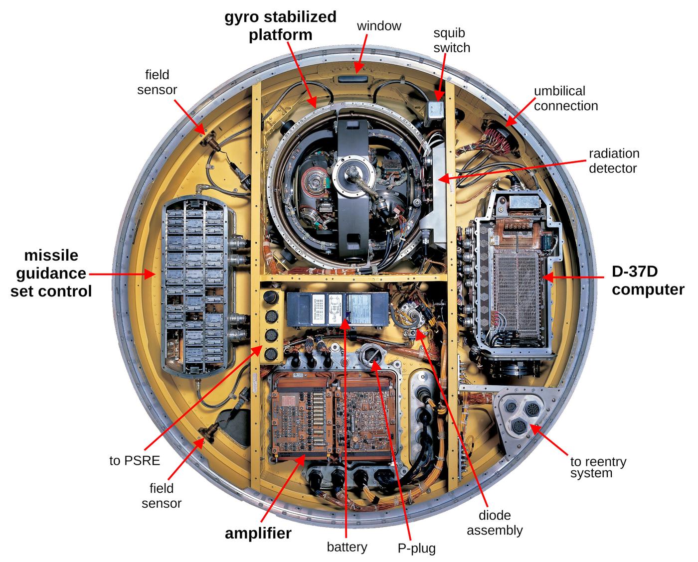
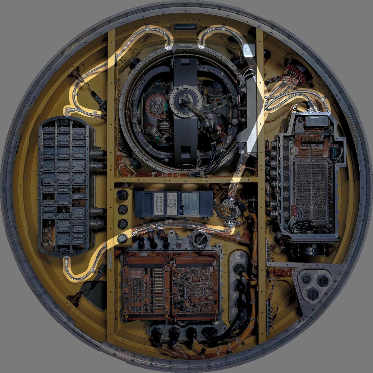
The diagram below shows the guidance system of the Minuteman III missile (1970). This guidance system contains over 17,000 electronic and mechanical parts, costing $510,000 (about $4.5 million in current dollars). The heart of the guidance system is the gyro stabilized platform, which uses gyroscopes and accelerometers to measure the missile's orientation and acceleration. The computer uses the measurements from the platform to determine the missile's position and guide the missile on its trajectory to the target. Other key components are the missile guidance set controller, which contains electronics to support the gyro stabilized platform, and the amplifier, which interfaces the computer with the rest of the missile. In this blog post, I take a close look at the components of the guidance system that was used until the early 2000s.2
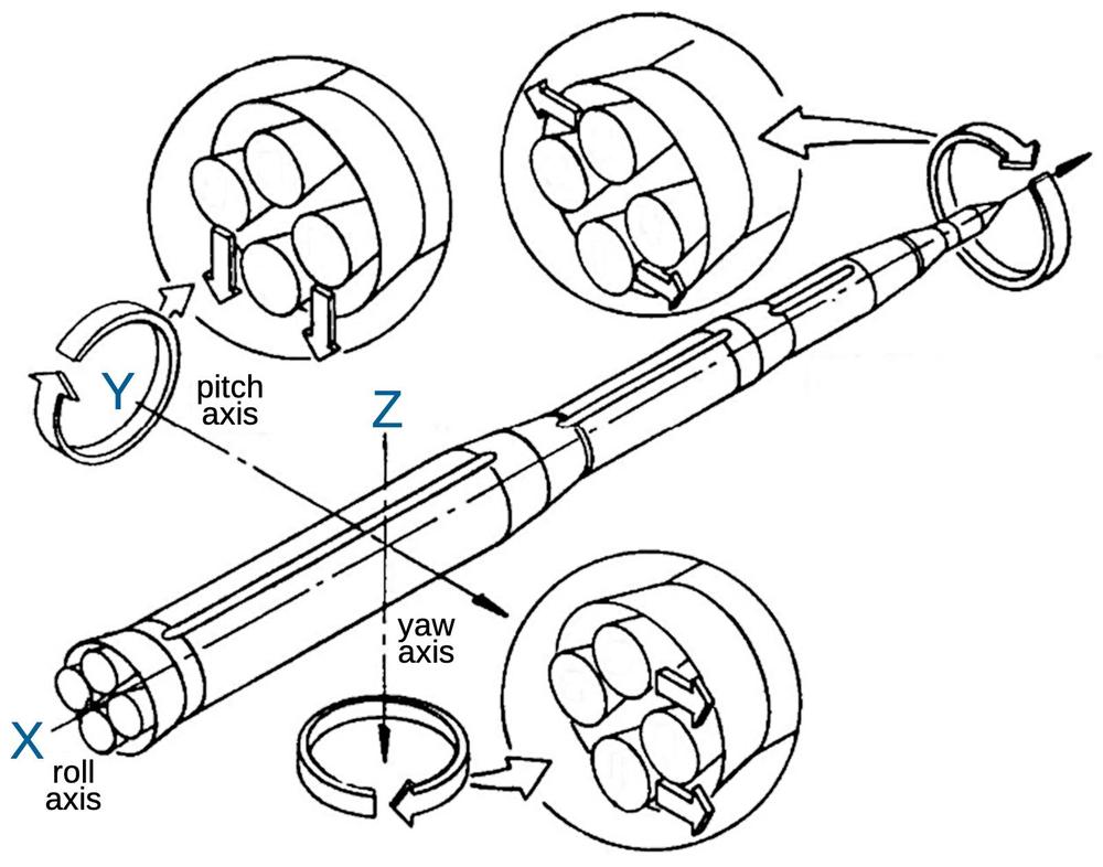
Fundamentally, the guidance computer constantly compares the missile position to the desired trajectory and generates the appropriate steering commands to keep the missile on track.3 The diagram below shows how directing the engine nozzles causes the missile to rotate around its three axes: roll, pitch, and yaw.4 In the silo, the roll angle (the azimuth) is aligned with the direction to the target. The missile takes off vertically and then the missile gradually rotates along the pitch axis to tilt over toward the target. During flight, adjustments along all three axes keep the missile on target. The Minuteman III has four rocket stages so the guidance computer jettisons each rocket stage and ignites the next stage in sequence.
The guidance platform
The idea behind inertial navigation is to keep track of the missile's position by constantly measuring its acceleration. By integrating the acceleration, you get the velocity. And by integrating the velocity, you get the position. Inertial navigation is self-contained, a big advantage for a missile since the enemy can't jam your navigation. The hard part is measuring the acceleration and angles with extreme accuracy, since even tiny errors are multiplied as the missile travels.
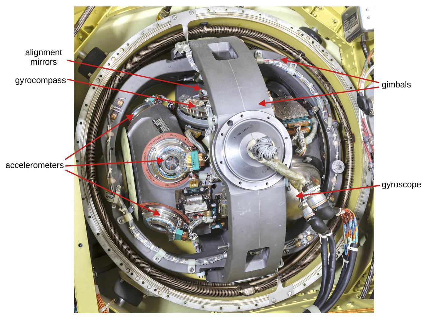
In more detail, the Minuteman's inertial guidance is built around a gyroscopically stabilized platform, which is kept in a fixed orientation. The platform is mounted on two beryllium gimbals. Feedback from gyroscopes drives three torque motors to rotate the gimbals to keep the stable platform in exactly the same orientation no matter how the missile twists and turns.
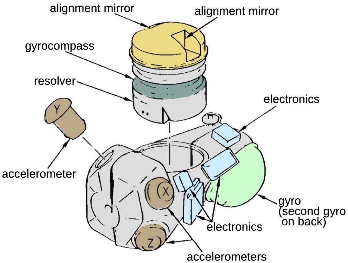
The diagram below shows the components of the stable platform, in approximately the same orientation as the photo above. Three accelerometers are mounted on the stable platform to measure acceleration. The accelerometers are oriented along three perpendicular axes so each one measures acceleration along one axis. (The accelerometer axes are not aligned with the platform axes; this distributes the acceleration (mostly "up") across the accelerometers, increasing accuracy.) The two alignment mirrors allow the stable platform to be aligned with a precise device called an autocollimator, as will be described below. The gyrocompass uses the Earth's rotation to precisely determine North, providing a backup alignment technique. Both the alignment mirrors and the gyrocompass can be rotated to a precise angle, reported by the resolver.
To target a Minuteman I missile, the missile had to be physically rotated in the silo to be aligned with the target, an angle called the launch azimuth. This angle had to be extremely precise, since even a tiny angle error will be greatly magnified over the missile's journey. Aligning the missile was a tedious process that used the North Star to determine North. Since the star was not visible from inside the silo, a complex surveying technique was used, using a surveyor's theodolite to measure the angles between the North Star and three concrete monuments outside the silo. Inside the silo, the closest monument was visible through a sighting tube, allowing the precise angle measurement to be transferred to the silo. After many more measurements inside the silo, a special device called an autocollimator was positioned precisely 90° from the desired launch azimuth. The autocollimator shot a beam of light through a window in the side of the missile, where it bounced off a mirror on the stable platform and returned to the autocollimator. If the returning beam wasn't exactly parallel, the autocollimator sent a signal to the missile, causing the stable platform to rotate as needed. The result of this process was that the stable platform was exactly aligned with the desired angle to the target.5
The guidance platform was completely redesigned for Minuteman II and III, eliminating the time-consuming alignment that Minuteman I required. The new platform had an alignment block with rotating mirrors. Instead of rotating the missile, the autocollimator remained fixed in the East position and the mirror (and thus the stable platform) was rotated to the desired launch azimuth. The new guidance platform also added a gyrocompass under the alignment block, a special compass that could precisely align itself to North by precessing against the Earth's rotation. At first, the gyrocompass was used as a backup check against the autocollimator, but eventually the gyrocompass became the primary alignment. For calibration, the alignment block also includes electrolytic bubble levels to position the stable platform in known orientations with respect to local gravity.6
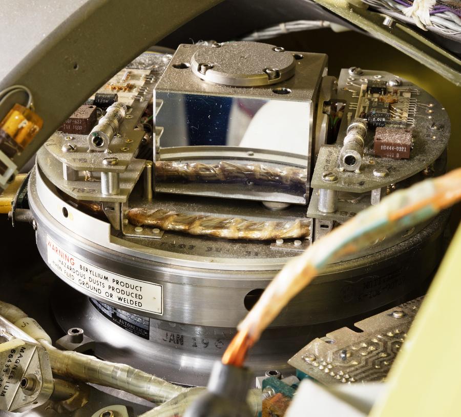
The photo above shows the alignment block on top of the gyrocompass. The front and back of the block are the precision mirrors that reflect the light beam from the autocollimator. The circles on top of the block and at the right are two level detectors, with set screws for exact adjustment. The platform has four level detectors, allowing it to be aligned against gravity in multiple positions. Like the gimbals, the gyrocompass assembly is made of beryllium due to its rigidity and light weight; it has a warning sticker because beryllium is highly toxic.
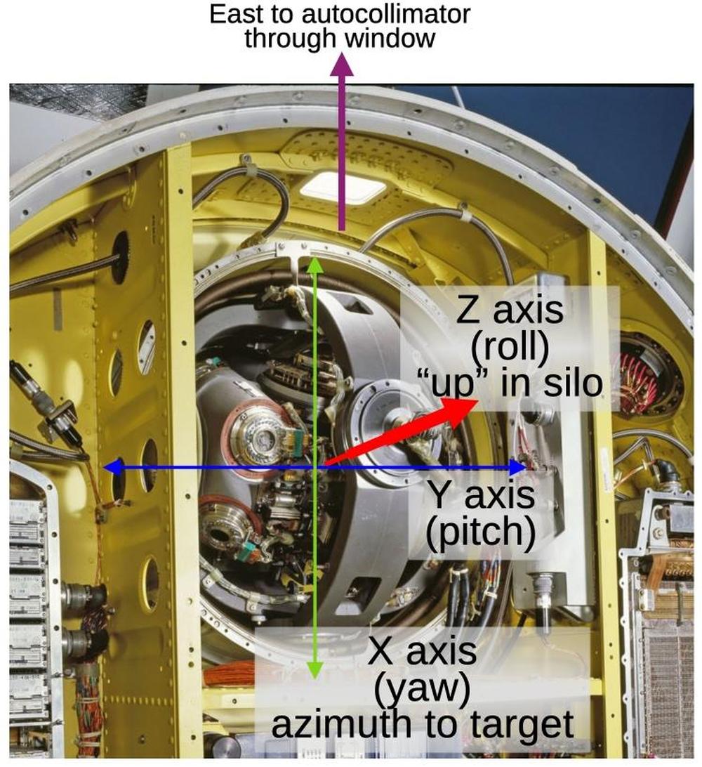
The diagram below shows how the axes align with the gimbals of the stable platform.7 Note the window at the top of the photo. Light from the autocollimator shines in through the window, reflects off the mirror on the alignment block, and returns through the window to the autocollimator. The autocollimator detects any error in alignment and signals the guidance system to correct its position accordingly.
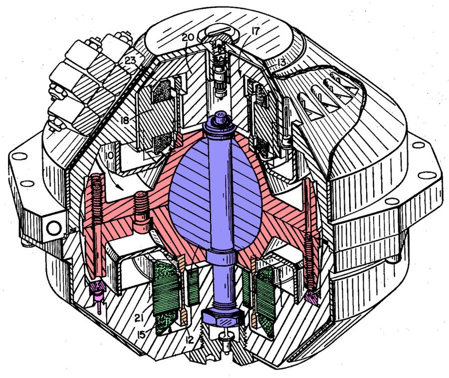
The stable platform uses gyroscopes to maintain its fixed orientation as the missile turns. The idea behind a gyroscope is that a spinning disk will tend to maintain its spin axis. The problem is that any friction, even from precision ball bearings, will reduce the accuracy. The solution in the Minuteman is a "gas bearing", where the gyroscope rotor is supported by an extremely thin layer of hydrogen. As shown below, the gyroscope is built around a stationary marble-sized ball (blue), fastened to the gyroscope frame at the top and bottom. The rotor (pink) is clamped around the equator of the ball and spins at high speed, powered by an induction motor (windings green, rotor yellow). If the gyroscope frame is tilted, the rotor will stay in its orientation. The resulting change in angle between the frame and the rotor is detected by sensitive capacitive pickups (purple). The gyroscope is sensitive to tilt in two axes: left-right, and front-back. Since nothing touches the rotor except the thin layer of gas around the ball, the influence of friction is minimal.
A gas-bearing gyroscope has the problem that when it starts or stops, the gas layer dissipates, allowing the rotor and the bearing to rub. The Minuteman missile's guidance system was kept continuously running, so starts and stops were infrequent. Moreover, when the gyroscope did need to be started, the electronics gave it a 40-volt jolt to get it up to speed quickly. Because the Minuteman's guidance system was always running—and its solid-fuel engines didn't require fueling—the missile could be launched in under a minute.
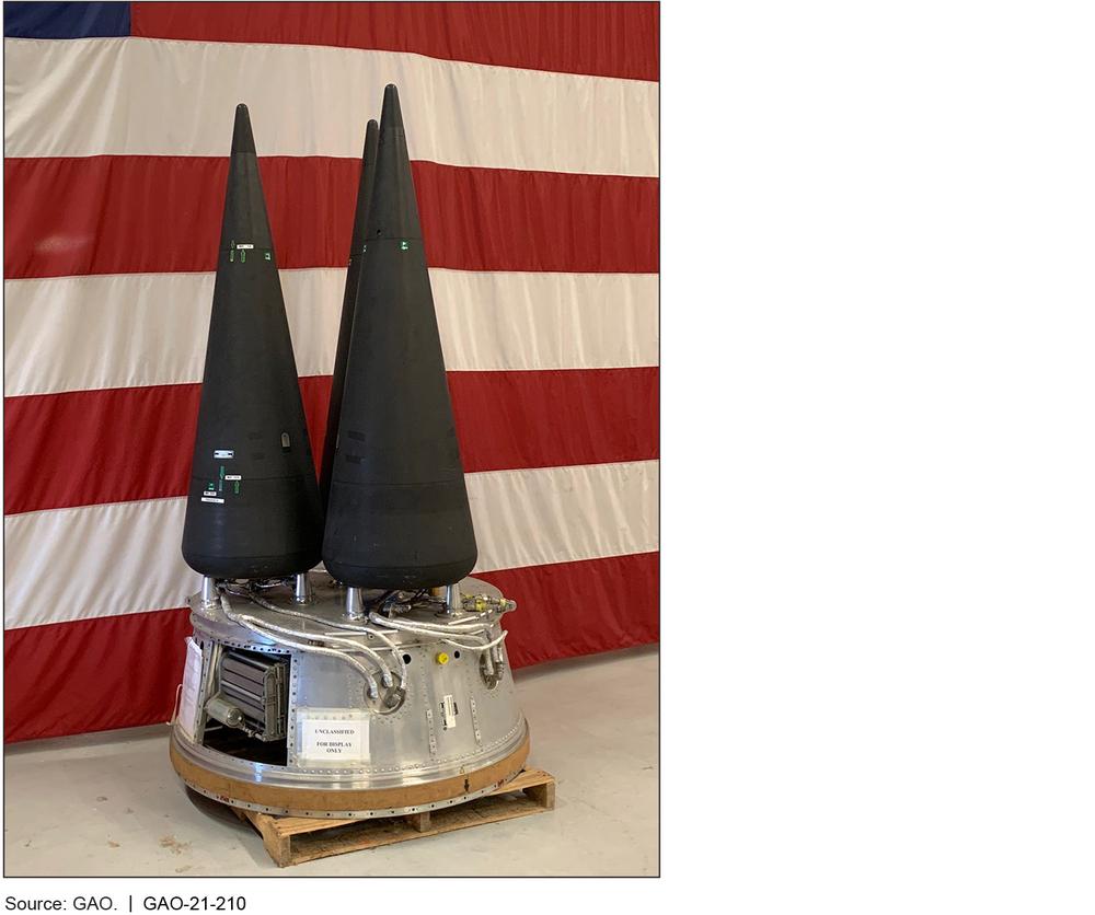
To summarize the guidance trajectory, a Minuteman flight is typically about 35 minutes,8 but only the first few minutes are powered by the rockets; the warheads coast most of the way on a ballistic trajectory. The first three rocket stages are active for just 180 seconds; this completed the boost phase for Minuteman I and II. However, the innovation of Minuteman III was that it held three warheads, a system called MIRV (Multiple Independently-targeted Reentry Vehicles). To direct these warheads to their targets, Minuteman III has a fourth stage, called PSRE (Propulsion System Rocket Engine), mounted just below the guidance system. The PSRE was active for 440 seconds, directing each warhead on its specific path. (Meanwhile, a retro-rocket sent the third stage in a random direction. Otherwise, it would tag along with the warheads, acting as a giant radar beacon for enemy anti-ballistic-missile systems.) The warheads travel very high, typically over 800 nautical miles (1500 km), more than three times the altitude of the International Space Station. As for the multiple-warhead MIRV, the Minuteman III missiles were converted back to single warheads as part of the New START arms reduction treaty, with the last MIRV removed in June 2014.
The Minuteman D-17B computer
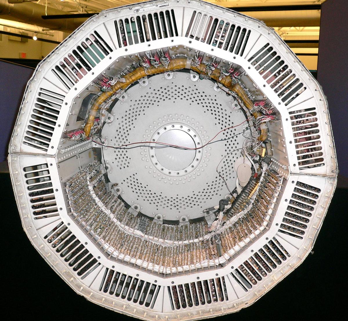
The guidance computer has a key role in the Minuteman missile, determining the missile's position from the stable platform data, executing a guidance algorithm, and steering the missile on the desired trajectory. Before explaining the D-37 computer used in Minuteman II and III, I'll start by discussing the D-17B computer used in the first Minuteman, since its characteristics strongly influenced the later computers. The Minuteman I computer was very primitive by modern standards. Although it was a 24-bit machine, it was a serial computer, operating on one bit at a time. The big advantage of serial processing is that it dramatically reduces the hardware requirements. Since the computer only processes one bit at a time, it uses a one-bit ALU. Moreover, the buses and datapaths are one bit wide rather than 24 bits. The disadvantage, of course, is that a serial computer is slow; the D-17B took 27 clock cycles (24 bits and three overhead) to perform any operation. At best, the computer could perform 12,800 additions per second.
The computer has an unusual cylindrical structure, 29 inches (74 cm) in diameter, designed to fit the diameter of the Minuteman missile. The computer itself is the bottom half of the cylindrical shell. The top half is the electronic equipment chassis, holding the power supplies for the computer and the stable platform, as well as servo control amplifiers, oscillators, and converters.
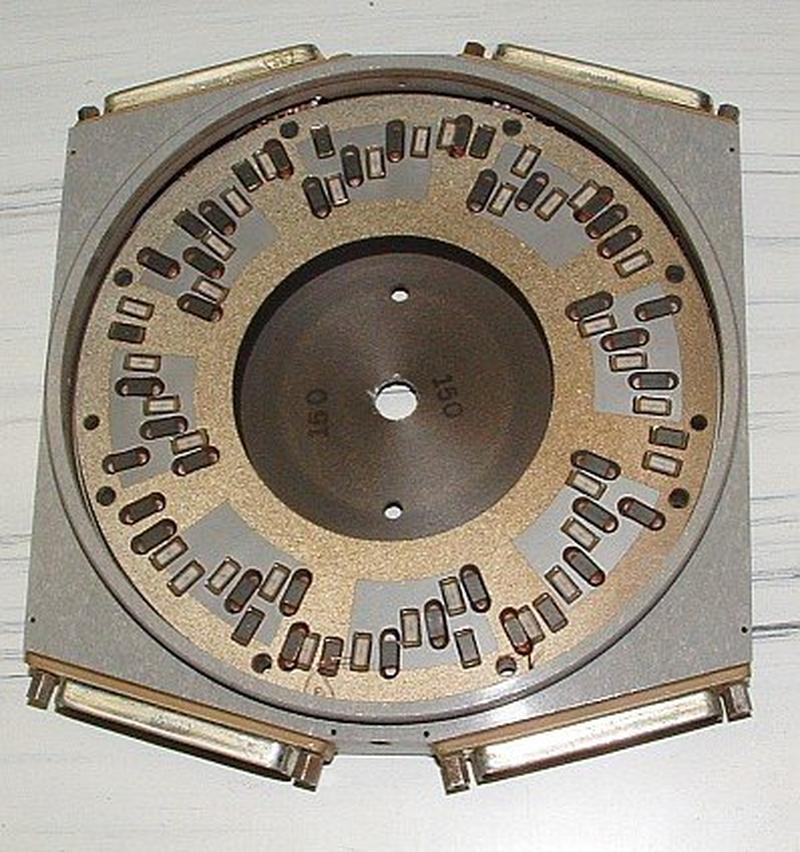
The computer doesn't have any RAM. Instead, all instructions, data, and registers are stored on a hard disk, but not like a modern hard disk. The disk has separate, fixed heads for each track so it can access tracks without seeking. (This approach is similar to a computer built around drum memory, except the drum is flattened.) In total, the disk held just 2727 24-bit words (approximately 8 Kbytes). The computer's serial processing and its disk-based storage worked well together. The disk provided data one bit at a time, which the computer would process serially. The results were written back to the disk, one bit at a time as calculation proceeded. The write head was positioned just behind the read head so a value could be overwritten as it was computed.
The photo below shows the numerous read and write heads for the D-17B's hard disk. Note that the heads are fixed (unlike modern hard drives), and the heads are widely distributed across the surface. (There is no need for different tracks to be aligned.) I believe that the green and white heads in pairs are for the "regular" tracks, while the heads with other spacings implement registers and short-term storage called loops.9
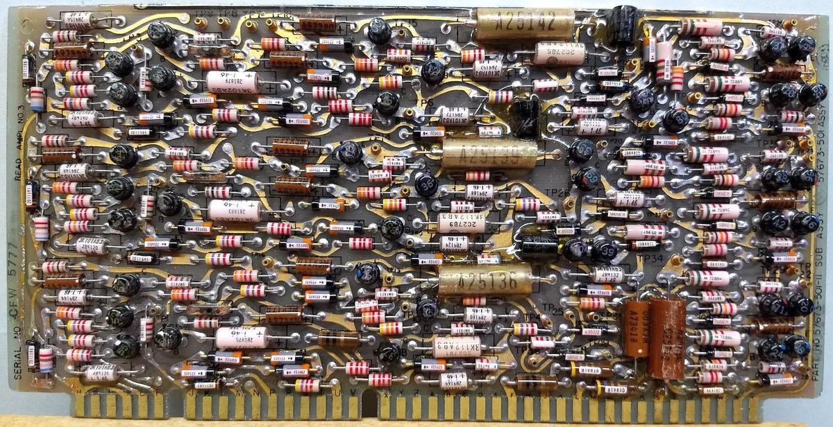
The D-17B computer was transistorized. The photo below shows one of its circuit boards, crammed with transistors (the black cylinders), resistors, diodes, and other components. (This board is a read amplifier, amplifying the signals from the hard disk.) The computer used diode-resistor logic and diode-transistor logic to minimize the number of transistors; as a result, it used 6282 diodes and 5094 resistors compared to 1521 silicon and germanium transistors (source).
The computer supported 39 instructions. Many of the instructions are straightforward: add, subtract, multiply (but no divide), complement, magnitude, AND, left shift, and right shift. The computer handled 24-bit words as well as 11-bit split words, so many of these instructions had "split" versions to operate on a shorter value. One unusual instruction was "split compare and limit", which replaced the accumulator value with a limit value from memory, if the accumulator value exceeded the limit.
The focus of the computer was I/O with 48 digital inputs, 26 incremental inputs, 28 digital outputs, 12 analog voltage outputs, and 3 pulse outputs for gyro control. The computer had special instructions to support the various inputs and outputs.10 For example, to integrate pulse signals from the stable platform, the computer had instructions to enter and exit "Fine Countdown" mode, which caused two special registers to operate as digital integrators, in parallel with regular computation (details).
The D-37 computer
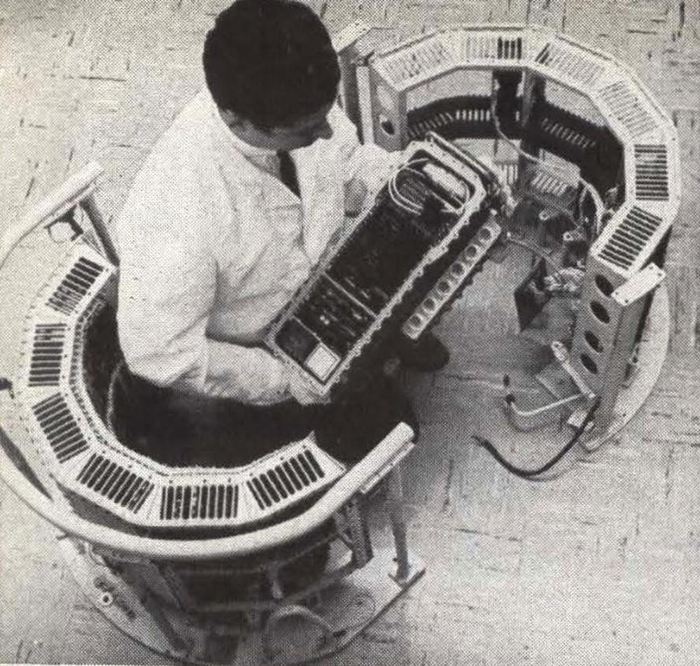
For the Minuteman II missile, Autonetics built the D-37 computer, one of the earliest integrated circuit computers. By using integrated circuits, the guidance computer was dramatically shrunk, increasing range, functionality, and accuracy. The photo below compares the size of the older D-17B computer (half-cylinder) with the D-37B (held by the engineer).
Although the main task of the computer is guidance, with the increased capacity of the D-37, the computer took over many of the tasks formerly performed by ground support equipment. The D-37 managed "ground control and checkout, monitoring, communication coding and decoding, as well as the airborne tasks of navigation, guidance, steering, and control" (link).
The D-37 had several models. The D-37A was the prototype system, while the D-37B was deployed in the first 60 Minuteman II missiles. The Air Force soon realized that nuclear radiation posed a threat to the computer, so they developed the radiation-hardened D-37C.11 The Minuteman III used the D-37D, an improved and slightly larger version. Even with additional disk space, program memory was so tight that software features were dropped to save just 47 words.
As far as architecture and performance, the D-37 computer is almost the same as the D-17B, but extended. Most importantly, the D-37 kept the serial architecture of the D-17B, so it had the same slow instruction speed. The D-37 kept the instruction set of the D-17B, with additional instructions such as division, logical OR, bit rotates, and more I/O, giving it 58 instructions versus 39 in the older computer. It expanded the hard disk storage, but with a double-sided disk providing 7222 words of storage in the D37-C.12 The D-37 included division implemented in hardware (which the D-17B didn't have), along with a faster hardware implementation of multiplication, improving the speed of those instructions.13 The D-37C added more I/O lines, as well as radio input and 32 analog voltage inputs.
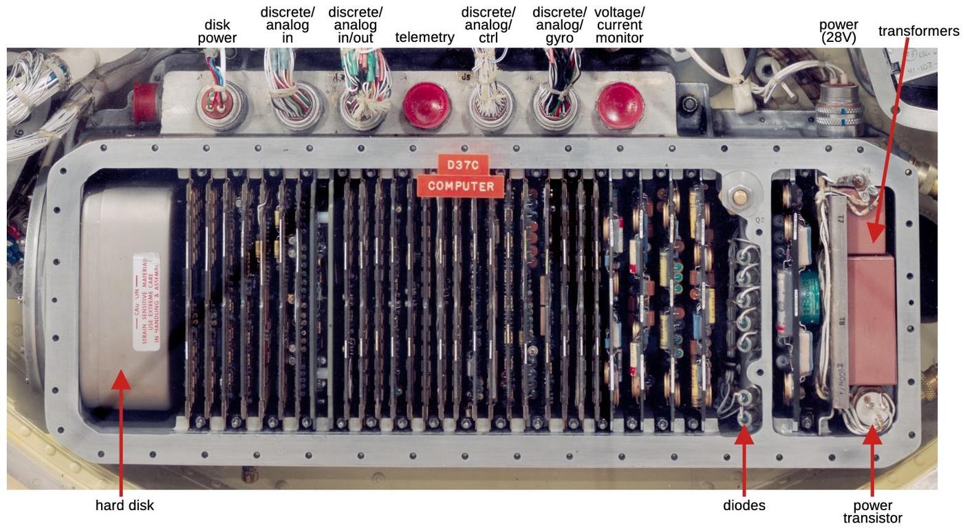
The diagram below shows the D-37C computer, used in the Minuteman II. At the left is the hard disk that provides the computer's memory. Most of the computer is occupied by complex circuit boards covered with flat-pack integrated circuits. At the right is the advanced switching power supply, generating numerous voltages for the computer (±3, 6, 9, 12, 18, and 24 volts). The connectors at the top provide the interface between the computer and the rest of the system. Because the computer has so many digital (discrete) and analog signals, it uses multiple 61-pin connectors (details).
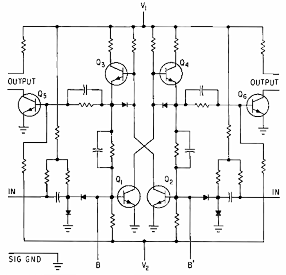
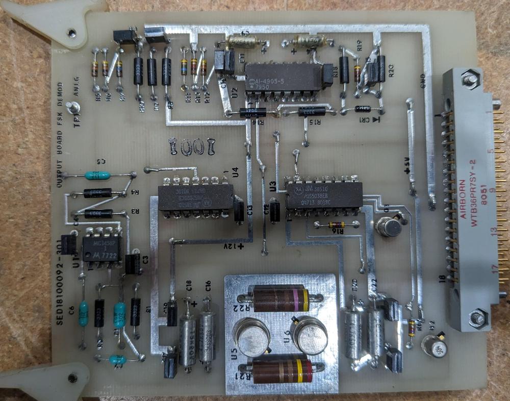
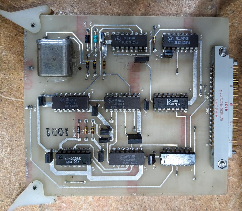
The D-37C computer was built from 22 different integrated circuits, custom-built by Texas Instruments for the Minuteman project. These chips ranged from digital functions such as NAND gates and a flip-flop to linear amplifiers to specialized functions such as a demodulator/chopper. Texas Instruments sold the Minuteman series integrated circuits on the open market, but the chips were spectacularly expensive ($55 for a flip-flop, over $500 in current dollars) and not as popular as TI's general-purpose integrated circuits.14 The circuit boards were very complex for the time, with 10 interconnected layers. Each board was about 4 × 5½ inches and held about 150 flatpack integrated circuits, with components on both sides.
The growth of the integrated circuit industry owes a lot to the Minuteman computer and the Apollo Guidance Computer, both developed during the early days of the integrated circuit. These projects bought integrated circuits by the hundreds of thousands, helping the IC industry move from low-volume prototypes to mass-produced commodities, both by providing demand and by motivating companies to fix yield problems. Moreover, both computers required high-reliability integrated circuits, forcing the industry to improve its manufacturing processes. Finally, Minuteman and Apollo gave integrated circuits credibility, showing that ICs were a practical design choice.
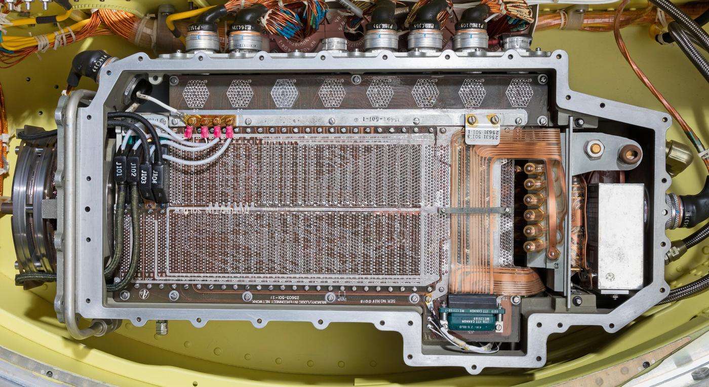
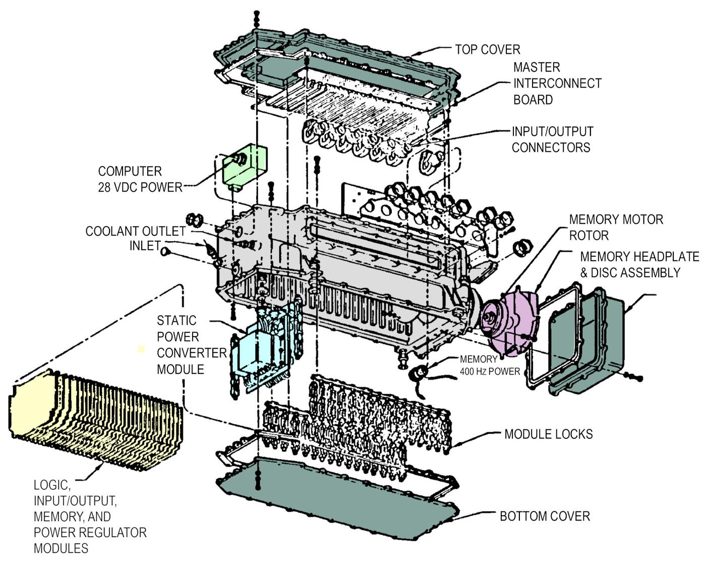
The Minuteman III used the D-37D computer, which had about twice the disk capacity, 14,137 words. The layout is similar to the D-37C above, with the disk drive on the left and the power supply on the right. Since the computer is mounted "upside down", the boards are not visible inside, blocked by the interconnect board.15 Note the use of flexible PCBs, advanced technology for the time, soldered with low-melting-point indium/tin solder.
By 1970, the D-37 computer had made the cylindrical D-17B obsolete. The government gave away surplus D-17B computers to universities and other organizations for use as general-purpose microcomputers. Dozens of organizations, from Harvard to the Center for Disease Control to Tektronix jumped at the chance to obtain a free computer, even if it was slow and difficult to use, forming a large users group to share programming tips.
The P92 amplifier
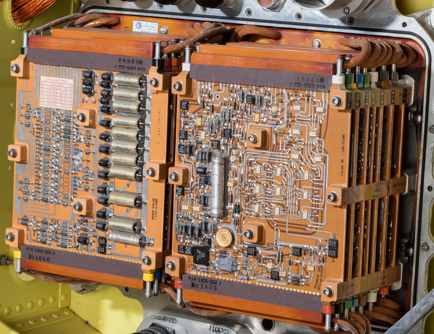
The amplifier provides the interface between the computer and the rest of the missile. The amplifier sends control signals to the missile's four stages, controlling the engines and steering. (The electronic circuitry from the Minuteman I's nozzle control units was moved to the amplifier, simplifying maintenance.) Moreover, the Minuteman has explosive ordnance in many places, ranging from small squibs that activate valves to explosives that separate the missile stages. The amplifier sends the high-current (30 amp) signals to detonate the ordnance, while monitoring the current to detect faults.16 The amplifier acts as a safety device for the ordnance, blocking signals unless the amplifier has been armed with the proper code. The amplifier sends control signals to the reentry system (i.e. the warheads) as well as the chaff dispenser, which emits clouds of wires to jam enemy radar. The amplifier also sends and receives signals through the umbilical cable from the ground equipment.
The photo above shows the amplifier with its cover removed. The amplifier is constructed as two stacks of six circuit boards, on top of a double-width power supply board. At the top and bottom of each board, connectors with thick cables connect the boards to the rest of the system. Each board is a multi-layer printed-circuit board built on a thick magnesium frame for cooling. The amplifier has five power switching boards, a valve driver board, three servo amplifier boards, and an ACTR control board (whatever that is). The system board is visible on the left, with large capacitors and precision 0.01% resistors. To its right is the decoder board, presumably decoding computer commands to select a particular I/O device. Note the extensive use of Texas Instruments flat-pack integrated circuits on this board, the tiny white rectangles.
Missile Guidance Set Control
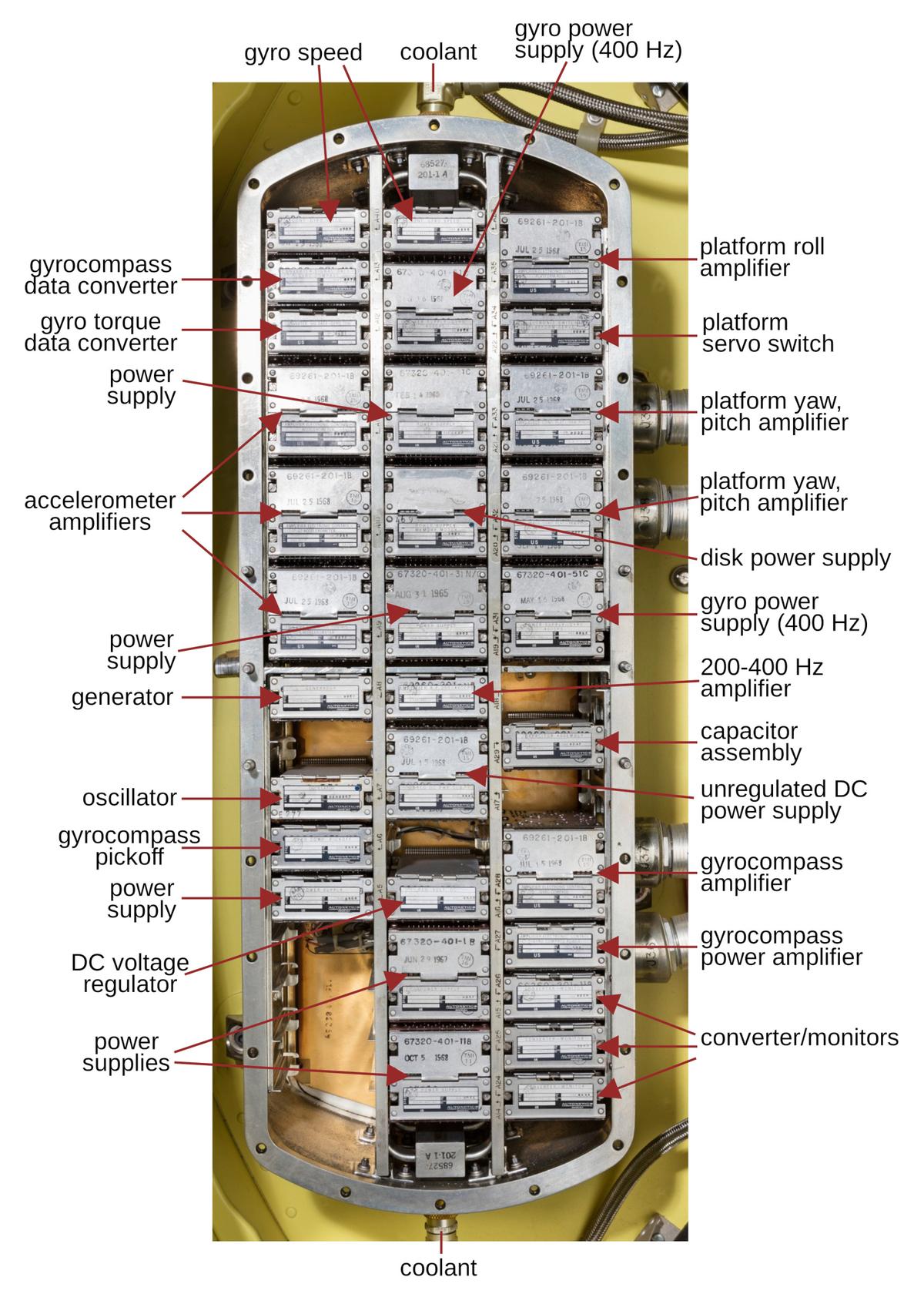
The Missile Guidance Set Control (MGSC) contains the electronics to power and run the inertial measurement unit (IMU), providing the interface to the computer. The MGSC handles the platform servo loop, accelerometer server loops, gyroscope torquing, gyrocompass torquing and slew, and accelerometer temperature control.17 One unexpected function of the MGSC is powering the computer's hard disk, supplying 400 Hz, 3-phase power at 27.25 volts (source).
The MGSC is constructed from hinged metal modules, each with a particular function, shown above. The modules are constructed around printed circuit boards. Two large connectors at the right of the MGSC provide electrical connectivity with the IMU and computer. At the top and bottom of the MGSC are connections for coolant. The MGSC is roughly equivalent to the top half of the Minuteman I's cylindrical guidance system, opposite the computer half. The MGSC is unchanged between the Minuteman II and Minuteman III. The MGSC is normally covered with a metal cover that provides radiation protection, but the cover is missing in the photo above.
Battery
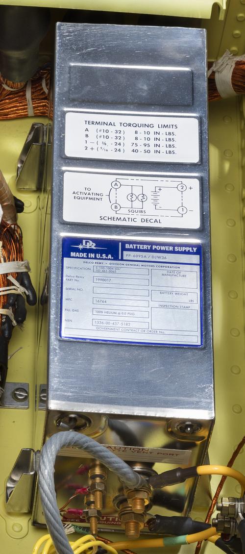
The battery in the Minuteman Guidance System is very unusual, since it is a "reserve battery", completely inert until activated. It is a silver/zinc battery with the electrolyte stored separately, giving the battery an essentially infinite shelf life. To power up the battery during a launch, a gas generator inside the battery is ignited by a squib. The gas pressure forces the potassium hydroxide electrolyte out of a tank and into the battery, energizing the battery in under a second. The battery can only be used once, of course, and you can't test it. The battery was built by Delco-Remy (a division of General Motors) (details). It provides 28 volts at 14.5 Amp-hours, powering the guidance system and most of the missile; a separate battery powers the first-stage rocket.
The photo above shows the battery mounted inside the guidance system. Note the two thin wires attached to the posts on the left front of the battery to enable the battery, and the thick power wires bolted to the posts on the right. Above these posts is an "electrolyte vent port"; I'm not sure what prevents caustic electrolyte from spraying out under high pressure.
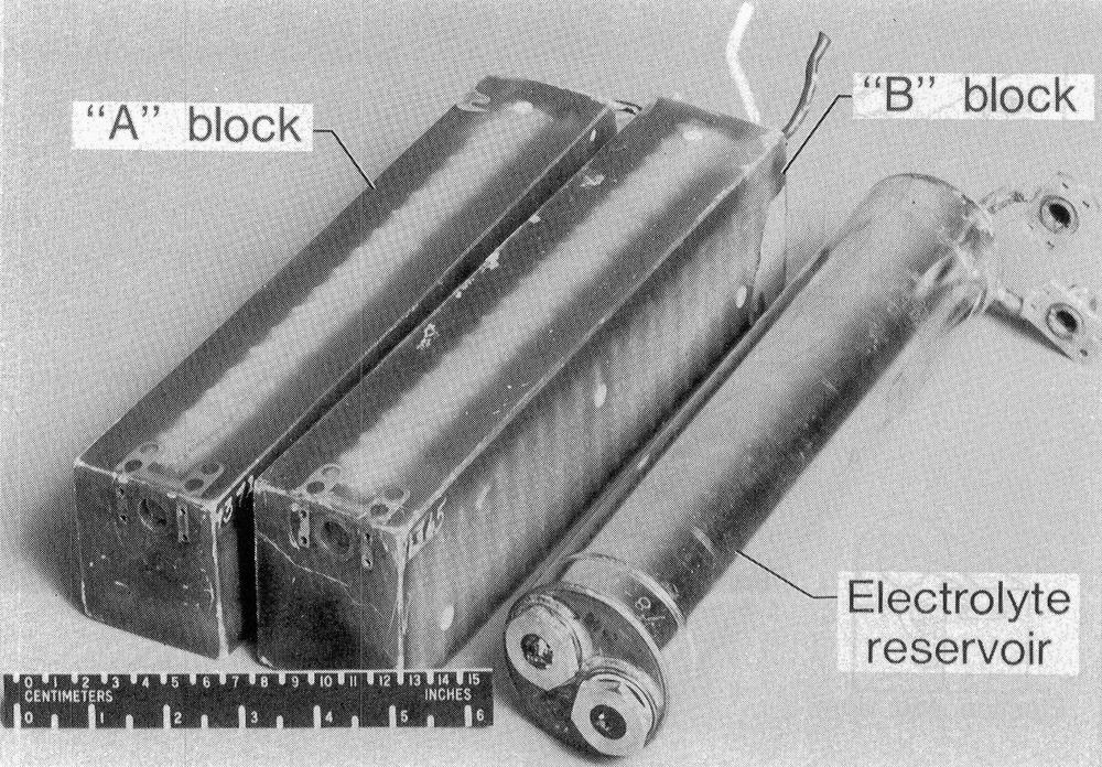
The photo below shows the construction of a Minuteman I battery, similar but with two independent battery blocks. The two round gas generators on the front of the electrolyte tube force the electrolyte into the battery sections.
Squib-activated switch
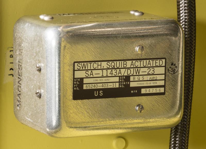
Another unusual component is the squib-activated switch. This switch is activated by a small explosive squib; when fired, the squib forces the switch to change positions. This switch may seem excessively dramatic, but it has a few advantages over, say, an electromagnetic relay. The squib-activated switch will switch solidly, while the contacts on a relay may "chatter" or bounce before settling into their new positions. An electromagnetic relay may require more current to switch, especially if it has large contacts or many contacts. However, like the battery, the squib-activated switch can only be used once.
The purpose of the switch is to disconnect important signals, known as critical leads, during launch. The Minuteman missile has an umbilical connection that provides power, cooling, and signals while the missile is in the silo. Just before the umbilical cable is disconnected, the switch severs the connections for the master reset signal along with an enable and disable signal. Presumably, these control signals are cleanly disconnected to avoid stray signals or electrical noise that could cause problems when the umbilical connection is pulled off.
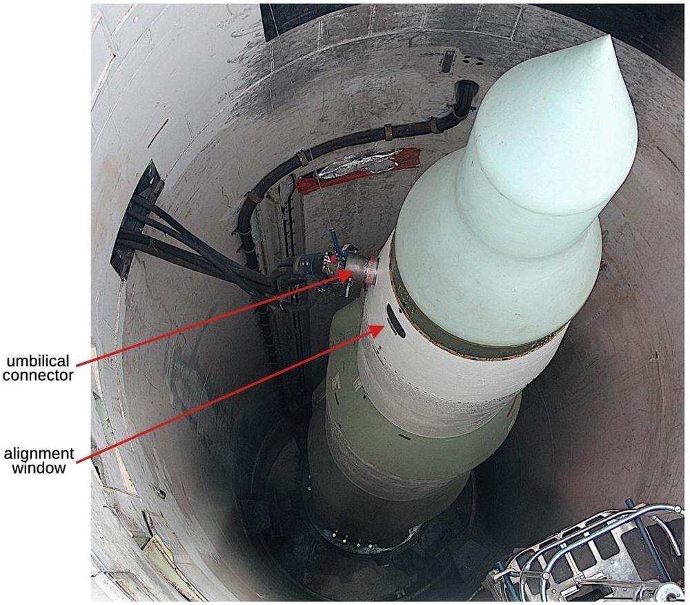
The photo below shows the umbilical cable connected to a Minuteman II missile in its silo. Also note the window in the side of the missile to allow the light beam from the autocollimator to reflect off the guidance platform for alignment.
Cooling
The guidance system is water-cooled while in the silo, using a solution of sodium chromate to inhibit corrosion. After launch, the guidance system operated for just a few minutes before releasing the warheads, so it operated without water cooling. (The stable platform has a fan and heat exchanger to keep it cool during flight.) The diagram below highlights the cooling lines. Coolant is provided from the ground support equipment through the umbilical connector in the upper right. It flows through the computer, diode assembly, MGSC, and stable platform. Finally, the coolant exits through the umbilical connector.
Diode assembly
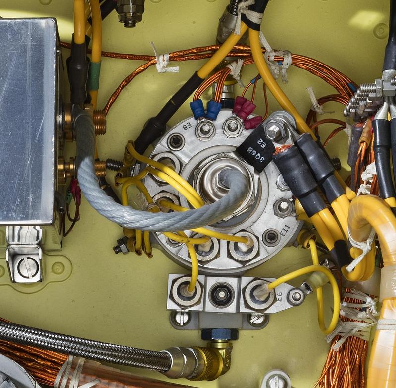
In the middle of the guidance system, the diode assembly consists of seven power diodes. These diodes control the power flow when switching from ground power to battery power. The photo below shows the diode assembly, with coolant connections at the top and bottom. The thick gray wire in the center of the diode assembly receives power from the battery just to the left.
Permutation plug
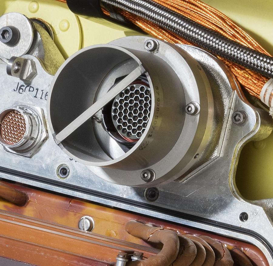
The Permutation plug (or P-plug) was the key cryptographic element of the guidance system, defining the launch codes for a particular missile. The P-plug looked similar to a hockey puck and plugged into a 55-pin socket attached to the amplifier. The retaining bar held the P-plug in place.
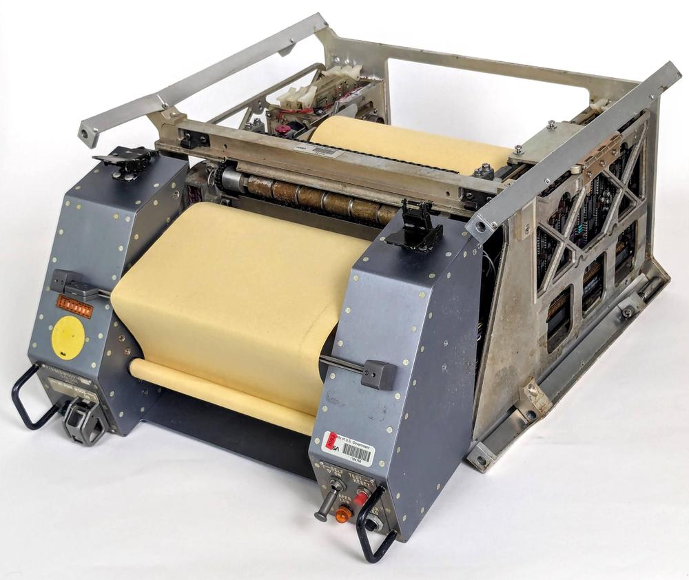
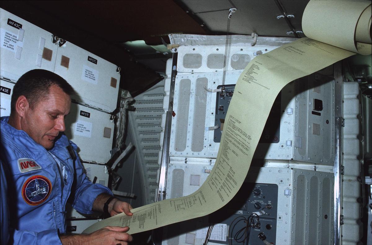
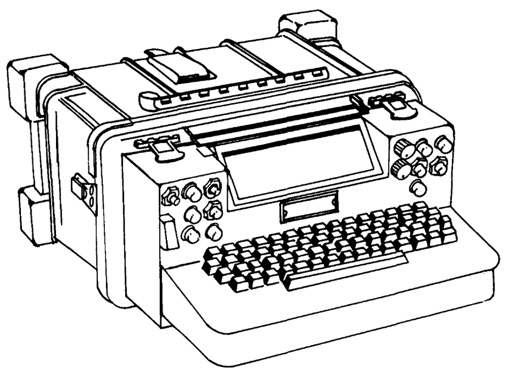
Because the security of the missile hinged on the P-plug, the P-plug was handled in a highly ritualized way, transported by a two-person team, an airman and an officer, both armed (source). After the guidance system underwent maintenance, the P-plug team would ensure that the plug was properly installed, just before the missile was bolted back together. There was also a lot of ritual around the disk memory, since it held security codes and targeting information.18 Before anyone could work on the computer, a special team would come to the silo and erase the memory. Afterward, another team would load up the computer from a magnetic tape (in the case of Minuteman III) or punched tape (earlier).19
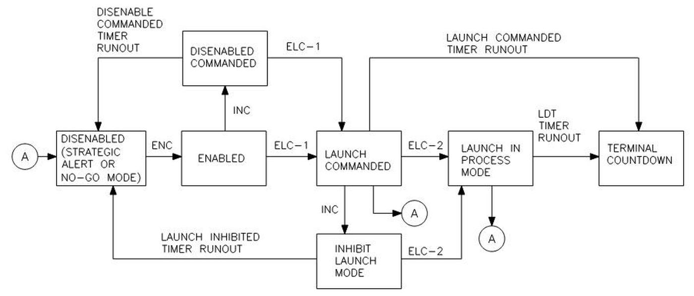
The missile launch codes are said to be split between the hard disk and the permutation plug. In particular, the missile software holds a two-word code for each of the five launch control facilities.22 The launch code in an Execute Launch Command (ELC) must match the combination of the P-plug value and the site-specific value on disk.23 Thus, the launch code is unique to each launch control site and each missile.24 As another security feature, a launch requires messages from two launch control sites, unless only one was available.25
Transient current detector
A nuclear blast has many bad effects on semiconductors and can cause transient errors. A rather brute-force approach was used to minimize this risk in the D-37C and D-37D computers: if a nuclear blast is detected, the computer stops writing to disk until the burst of radiation passes by. When the radiation level drops, the computer carries on from where it left off, extrapolating to make up for the lost time26 to minimize the error. Since all data is stored on the hard disk, the system doesn't need to worry about memory corruption as could happen with semiconductor RAM.
The Minuteman documents euphemistically refer to "operating in a hostile environment" for the ability to handle large pulses of radiation from a nearby nuclear explosion. Another euphemism is "seismic environment", when a nuclear blast near a silo could disturb the missile's targeting alignment. To get an idea of the expected forces, note that the launch officers were strapped into their seats with four-point harnesses to protect against the seismic environment.27
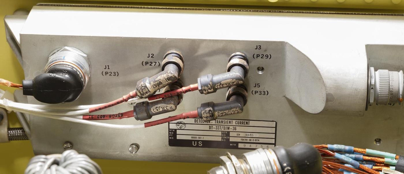
The "transient current detector" above detects dangerous levels of radiation. I couldn't find any details, but I suspect that it contains a semiconductor and detects transient current through the semiconductor induced by radiation. It would make sense to use a semiconductor similar to the ones in the computer so the detector's response matches the response of the computer, perhaps a matching Texas Instruments IC.
The Minuteman III also has two "field detectors" mounted on the outside of the guidance ring. These presumably detect large fluctuations in the electromagnetic field, indicating an electromagnetic pulse (EMP), different from the ionizing radiation picked up by the Transient Current Detector.
Conclusions
The Minuteman guidance system is full of innovative technologies. Among other things, Minuteman I used an early transistorized computer, and Minuteman II used one of the first integrated circuit computers. The Minuteman missile isn't just something from the past, though. There are currently 400 Minuteman missiles in the United States, ready to launch at a moment's notice and create global devastation. Thus, its technical achievements can't be glorified without reflecting on the negativity of its underlying purpose. On the other hand, Minuteman has succeeded (so far) in its purpose of deterrence, so it can also be viewed in a positive, peacekeeping role. In any case, the Minuteman technology is morally ambiguous, compared to, say, the Apollo Guidance Computer.
I plan to write more about the role of Minuteman and Apollo in the IC industry, so follow me on Mastodon as @[email protected] or RSS for updates. Probably the best overview of Minuteman is Minuteman weapon system history and description. The book Minuteman: A technical history has thorough information. For information on the missile targeting and alignment process, see Association of Air Force Missileers Newsletter, December 2006. The Minuteman guidance system is described in detail in The evolution of Minuteman guidance and control. Much of the imagery in this article is from the National Air and Space Museum. Thanks to Martin Miller for providing a detailed D-37C photo. He has taken amazing photos of nuclear equipment, published in his book Weapons of Mass Destruction: Specters of the Nuclear Age, so check it out.
Notes and references
-
The Minuteman missile was introduced in 1962, followed by the improved Minuteman II in 1965 and the Minuteman III in 1970. From 1966 to 1985, the US had 1000 Minuteman missiles fielded, but the number has been reduced since then due to various arms control agreements. At present, there are 400 active Minuteman III missiles spread among 450 launch sites. The Minuteman guidance system was updated in the early 2000s to a platform called the NS-50, using a computer based on a MIL-STD-1750A microprocessor. I'm not discussing that system in this post for reasons of space.
Although the Minuteman has undergone modernization projects, it is reaching the end of its life and is scheduled to be replaced by the Sentinel missile. The Sentinel program is encountering delays and is over budget by 80%, raising the risk of cancellation but the Sentinel program is proceeding as of July 2024. ↩
-
Disclaimer: This information is all from published sources. There's nothing secret, and it's mostly obsolete from 60 years ago. I don't have access to a Minuteman system (unlike the Titan), so this post is based on publications and photos, rather than hands-on experience. I've tried to be accurate, but I'm sure there are errors. ↩
-
Different guidance algorithms can be used, such as Q-guidance, delta guidance, explicit guidance, and numerical integration; the more advanced algorithms require better computers but provide easier targeting, better accuracy, and more ability to correct for course deviations (see Present and Advanced Guidance Techniques). Q-guidance uses a precomputed "Q matrix" to constantly determine the direction in which velocity needs to be gained, while delta guidance attempts to keep the missile along a precomputed trajectory by using polynomials. In explicit guidance, the equations of motion are solved to determine the steering direction. Minuteman used delta guidance at first, but moved to "hybrid explicit" guidance when the computer became more advanced. See Minuteman: A technical history, page 234 for more on targeting algorithms. ↩
-
On Minuteman I, the three stages were steered by changing the direction of the rocket nozzles. Minuteman II, however, used a single fixed nozzle on the second stage but injected fluid into the exhaust to steer the missile, a technique called liquid injection thrust vector control. The Minuteman III used this technique on the third stage as well, injecting a strontium perchlorate solution. (Small nozzles powered by a gas generator are used for roll control, since directing the exhaust won't produce roll motion.) The thrust control liquid was Freon 114B2, which turned out to be harmful to the ozone layer, so it was replaced in the 1990s with perfluorohexane. ↩
-
Strictly speaking, the launch azimuth wasn't aimed at the target. Because the Earth rotated during the missile's flight, the launch azimuth was aimed at where the target would be when the warhead landed. Another factor was the Minuteman I had a limited ability to steer off the launch azimuth, about 10°, allowing the missile to switch between two targets at launch time. ↩
-
The Minuteman guidance system is designed to achieve as much accuracy as possible. One problem is that the gyroscopes and accelerometers aren't perfect, but have small errors due to friction and other factors. Moreover, the construction of the stable platform isn't exact; components that should be parallel or perpendicular will have tiny angle errors. To deal with these problems, the missile performs periodic calibrations ranging from some every 15 minutes to some every few months.
To assist with calibration, the guidance platform contains electrolytic bubble levels, similar to an ordinary carpentry level, but extremely sensitive. Each bubble level contains wires positioned partially in the bubble and partially in the conductive electrolyte fluid. As the bubble shifts, the amount of wire in the fluid changes, changing the measured resistance. These levels are so sensitive that The levels allow the stable platform to be rotated to known positions relative to gravity for calibration.
The top of the gyrocompass has two mirrors for calibration, allowing the missile platform to rotate exactly 180° relative to the autocollimator. Every 15 minutes, the platform would flip over to measure the gyroscope and accelerometer signals in the opposite orientation. This allowed much better calibration, canceling out errors and improving the missile accuracy. Other calibrations were performed less frequently, such as checking each accelerometer in the up and down positions. Every 90 days, a calibration called PSAT (Perturbation Self-Alignment Technique) pitched the platform by 90° and then slowly rotated the gyrocompass around the vertical to simulate the Earth's rotation (details).
Another alignment measurement checks the angle between the two mirrors. The two mirrors on the alignment block are supposed to be parallel, but they won't be exactly parallel. The guidance platform periodically rotates the mirror assembly to check one mirror and the other against the autocollimator to compute the angle between the mirrors, called zeta. (See Software Validation Study, page A-94.)
These calibrations permitted the measurement of small biases and imperfections in the gyroscopes and accelerometers; this data was fed into the guidance calculations to squeeze out as much accuracy as possible. These measurements also provided statistical tracking of the devices so they could be replaced if their performance started to deteriorate. ↩
-
Inconveniently, I found contradictory sources about the Minuteman coordinate system. Most sources specify Z as the roll axis, but one detailed paper swaps the X and Z axes, maybe to match simulation software. Examining Figure 5 closely shows that the new axis names were drawn in by hand. ↩
-
The flight time of Minuteman depended on the distance and trajectory. The Minuteman's range is said to be 13,000 km. For a closer target, there are two possible trajectories: a high path and a low path. Being direct, the low path could take about 25 minutes, while the high path would reach over 1500 nautical miles (almost 3000 km, seven times the altitude of the ISS) and take 45 minutes. See A simulation of Minuteman Trajectories. ↩
-
The disk holds a timing track, which provides the timing for the computer, giving it a 345.6 kHz clock speed. Note that all operations in the computer are synchronized to the disk, rather than a clock inside the computer. One consequence of this is that the processor speed depends on the disk speed, so it isn't as precise as most computers, which generate the clock from a quartz crystal. The processor timing is very important for a guidance computer, since its calculations of positions depend on the time step. If the processor is running fast or slow, the position will be correspondingly wrong. The solution is that the computer calculates a parameter "tau", the ratio between processor time and wall clock time. The computer receives an interrupt exactly once per second; by counting the number of instructions executed between interrupts, the computer can compute tau and ensure that the calculations are accurate. ↩
-
The computer has 8-bit analog-to-digital converters. The D-37C supports 32 analog inputs with a range of +/- 10 volts (source). It also has four digital-to-analog outputs with 8-bit accuracy, also +/- 10 volts.
In the D-17B, nine analog outputs control the rocket steering, providing roll, pitch, and yaw to the three stages, while three analog outputs go to the stable platform, probably positioning the gimbals. ↩
-
The housing for the stable platform provides radiation shielding; it is one of the few parts of the guidance system that is officially secret, but is said to be tantalum sheeting (see Minuteman: A technical history page 224). Although the computer is also said to have radiation shielding, it is curiously not on the secret list. ↩
-
Sources give different memory capacities. The reason is that in addition to the regular memory, part of the disk is used for special purposes including registers and rapid access loops. The problem with the regular memory is that the processor may need to wait for an entire disk revolution to access a particular word. The solution is rapid access loops: by putting the write head just upstream of the read head, the data can be accessed more rapidly. For instance, if the write head is positioned one word length upstream, the word can be read (and rewritten) every cycle, providing immediate access to a single word. Putting the write head further upstream allows storage of longer values, with a corresponding longer wait. The D-37C has ten rapid-access channels of one to 16 words (source). The regular memory in the D-37C consists of 56 channels (i.e. tracks) of 128 words, totaling 7168 words. Counting the loops and registers yields the higher memory capacity of 7222 words. ↩
-
The differences between the D-17B and D-37C instruction sets are described here. ↩
-
The schematic for the Minuteman's flip-flop IC is shown below. This is a complex circuit for the time, with six transistors along with numerous resistors, diodes, and capacitors.
Flip-flop schematic. From Integrated circuits go operational, Electronics, Feb 15, 1963. -
The diagram below shows an exploded view of the D-37D computer (rotated 180° from the earlier photo).
Exploded view of the D-37D computer. Modified and fixed from Minuteman weapon system history and description. -
The danger of these explosives is illustrated by a bizarre accident summarized by "The warhead is no longer on top of the missile." At 3:00 pm on December 5, 1964, two airmen were in the missile silo, troubleshooting a fault in the security system. One airman removed a fuse, triggering a loud explosion and the nuclear warhead fell off the missile, falling 75 feet to the floor of the silo. Nobody was injured and the warhead was hoisted out a few days later without incident.
The problem was that the airmen used an "unauthorized tool" (a screwdriver) to remove the fuse, briefly shorting power to ground. This caused a current on a ground line connected to the missile through an umbilical cable. Inside the missile, the retrorocket for the warhead had an igniter, but a short on its connector caused another connection to ground. This ground went out through a second umbilical, closing the circuit. (Apparently, the resistance between the two grounds was high enough that the path through the two shorts had enough current to ignite the igniter.) The force of the retrorocket flung the warhead off the rocket.
More details are in this report and this report. (This incident is not the 1980 Damascus Titan incident, where a dropped 8-pound wrench socket led to the explosion of the missile, killing one person and injuring 21 others, while flinging the warhead out of the silo. The very interesting book Command and Control discusses the Damascus incident and other mishaps with nuclear weapons.) ↩
-
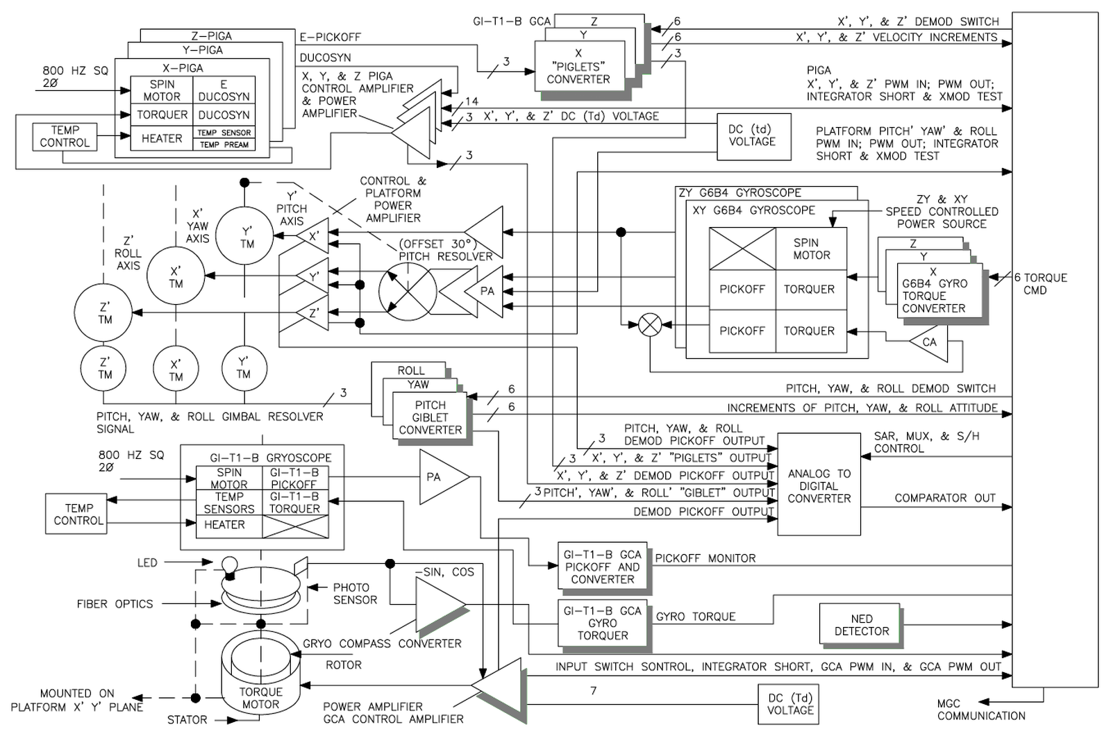
The functional diagram below shows the interactions between the stable platform and the guidance set. Shaded circuits are mounted on the stable platform, while others are in the control set. This diagram is for the later NS-50 platform, but it should be mostly relevant to the NS-20 used in Minuteman III earlier. At the top are the feedback loops for the PIGA accelerometers (top). The torque motors (TM) in the middle provide feedback through the gimbals for the gyroscopes. Below that, the gyrocompass has a a feedback loop with its internal torquer. The torque motor at the bottom rotates the gyrocompass and mirrors with feedback through the optical resolver.
Platform Control Functional Diagram. From Technical Reference Handbook, SELECT WS133A, D2-27524-5, Fig. 3-12, page 3-68. -
The Air Force was especially concerned with keeping the targeting information secret; the people launching the missiles had no idea what the targets were. It occurs to me, though, that since the Minuteman I missile had to be physically rotated in its silo to exactly line up with the target, one presumably could draw an azimuth line on the map and know the target was along the line. ↩
-
The Minuteman computer has a conditional fill mode, where the computer can't be loaded with a new program unless the first four words match the first four words in memory channel 12. This ensures that the computer can't be loaded with unauthorized software. This four-word code must be different from the P-plug value for two reasons. First, the P-plug value is not allowed to be stored in memory. Second, the filling code is four words, while the P-plug value is two words.
The P-plug held two hardwired code words that could be read by the processor.20 For security, the two words were not allowed to be in memory (i.e. the hard drive) at the same time. I assume it is called a Permutation Plug for historical reasons; the Saturn V booster used in Apollo used a security plug that provided a permutation of the 21-character code.21 (That is, it mapped 21 inputs to 21 outputs as a permutation.) ↩
-
The processor read the P-plug code words by first triggering the discrete output #25 with the
DOB 25instruction (Discrete Output B) and then reading the value (twice for reliability). The process was repeated with output #6. Finally, the discretes were cleared withDOB 0(reference). ↩ -
The Apollo flights used "code plugs" to protect the Range Safety system from unauthorized access, since this system was capable of blowing up the Saturn V rockets (details). Signals were transmitted in a 21-symbol "alphabet" (encoded by 2 tones out of 7). The code plug permuted the 21 symbols in an arbitrary way. This wasn't a lot of security, just a simple substitution cipher, but it was sufficient for its role. A command consisted of 11 characters (9 for the address and 2 for the command), so the odds were low of hitting a valid message by chance. ↩
-
One feature of the Minuteman missile is that the missile sites themselves are uncrewed; the missile officers who launch the missiles work remotely, handling multiple missiles to reduce the personnel required. Specifically, each group of 10 missiles (called a "flight") is controlled by an underground launch control center. A squadron consists of 50 missiles. A "wing" is the largest grouping, handling 150 to 200 missiles, and attached to a particular Air Force base. At its peak, Minuteman had 1000 missiles divided among six wings in Missouri, Montana, North Dakota, South Dakota, and Wyoming, with missiles spilling across the Wyoming border into Colorado and Nebraska. ↩
-
Information on the launch code mechanism is from Technical Reference Handbook D2-27524-5, "System Engineering Level Evaluation Correction Team, WS133A", chapter 2. ↩
-
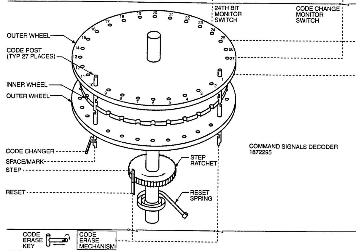
The Command Signals Decoder provides another layer of security. It is an electromechanical stepping decoder that blocks the first-stage rocket from igniting unless it receives the proper 27-bit code as part of an Enable command. (The Enable command (ENC) happens before the Execute Launch command (ELC); see the state diagram below.) Its operation is murky; my hypothesis is that the decoder acts much like a combination lock, with the 27 code posts raised or lowered by the input bits. If all the posts are in the proper position, the inner wheel is released, allowing it to rotate to the armed position and close the electrical firing circuit for the motor igniters. Specifically, the 27 posts have a high notch on one side and a low notch on the other, so the device is programmed by rotating each pin so the desired notch faces inward. When the device receives code bits, the wheel rotates one position for each bit and a solenoid raises or lowers the pin, depending on if it is a zero or one. If all pins are in the correct positions, the inner wheel can rotate through the notches, but if any pins are incorrect, the inner wheel will bind on that pin. The 27 bits are the "CSD(M) secure code", probably consisting of 24 code bits and three padding bits. Another Command Signals Decoder on the ground "CSD(G)" provides an interlock for ground ordnance.
The Command Signals Decoder, from Evolution of ordnance subsystems and components design in Air Force strategic missile systems.I think there are two motivations behind this complicated device. First, they want an interlock that is mechanical rather than electronic, since an electronic device can be affected unpredictably by radiation, power surges, component failure, programming errors, etc. Second, they want an interlock that physically disconnects the firing circuit so there is no path that can be triggered by stray current, lightning, EMP, etc.
The Minuteman's P92 amplifier assembly also blocks ordnance unless armed with a code. It's unclear if this is the same enable code as the Comand Signals Decoder or a different code.
The earlier Titan missile also had a code mechanism to prevent an unauthorized launch by blocking the engine. The Titan had a butterfly valve in the fuel line with a 6-digit code. If you don't enter the right code, the fuel line stays shut and the missile simply can't take off (video). ↩
-
A missile launch normally requires an Execute Launch Command (ELC) from two launch control sites, moving the missile to the "Launch in Process" mode. However, that raises the concern that there could only be one surviving site. The solution is that after receiving a single launch command, the missile starts a timer. If the "one-vote launch time" passes uneventfully, the missile is launched. However, another site can cancel a rogue launch during that time by sending an Inhibit Command (INC) message. The sites have a complex system to detect which sites are active and to determine the primary and secondary sites controlling each missile. (This is reminiscent of the Byzantine generals problem.)
The state machine for Minuteman missile status. From Technical Reference Handbook D2-27524-5, page 2-25. -
After detecting a nuclear blast, the Minuteman computer shuts down for an integral number of disk revolutions. When it comes back up, it double-counts the accelerometer pulses for the same number of disk revolutions to make up for the missed time (see Minuteman: A technical history pages 220 and 223). As long as not much changed during the lost time, the accuracy loss is small. Of course, this counter would need to be outside the part of the computer that gets shut down. ↩
-
Missiles were aligned to such accuracy that even running a diesel generator nearby could shift the silo enough to cause alignment problems, as happened with a Titan site. (See Association of Air Force Missileers Newsletter, March 2007, page 6.) A "seismic event" could also be an earthquake; the enormous 1964 Alaska earthquake—9.2 on the Richter scale—caused Minuteman guidance systems to lose alignment with the autocollimator (See Minuteman: A technical history page 221). ↩
