Showing posts with label reverse-engineering. Show all posts

Interesting BiCMOS circuits in the Pentium, reverse-engineered

Intel released the powerful Pentium processor in 1993, establishing a long-running brand of processors. Earlier, I wrote about the ROM in the Pentium's floating point unit that holds constants such as π. In this post, I'll look at some interesting circuits associated with this ROM. In particular, the circuitry is implemented in BiCMOS, a process that combines bipolar transistors with standard CMOS logic.

The photo below shows the Pentium's thumbnail-sized silicon die under a microscope. I've labeled the main functional blocks; the floating point unit is in the lower right with the constant ROM highlighted at the bottom. The various parts of the floating point unit form horizontal stripes. Data buses run vertically through the floating point unit, moving values around the unit.

Die photo of the Intel Pentium processor with the floating point constant ROM highlighted in red. Click this image (or any other) for a larger version.

Die photo of the Intel Pentium processor with the floating point constant ROM highlighted in red. Click this image (or any other) for a larger version.

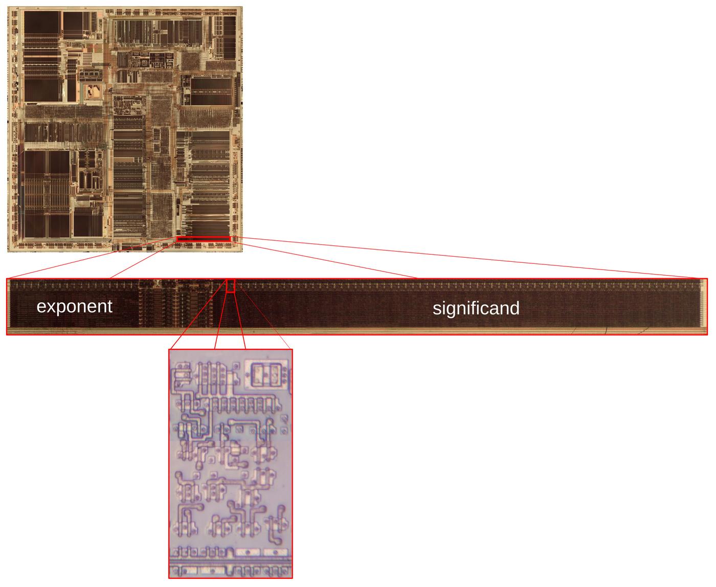
The diagram below shows how the circuitry in this post forms part of the Pentium. Zooming in to the bottom of the chip shows the constant ROM, holding 86-bit words: at the left, the exponent section provides 18 bits. At the right, the wider significand section provides 68 bits. Below that, the diagram zooms in on the subject of this article: one of the 86 identical multiplexer/driver circuits that provides the output from the ROM. As you can see, this circuit is a microscopic speck in the chip.

Zooming in on the constant ROM's driver circuits at the top of the ROM.

Zooming in on the constant ROM's driver circuits at the top of the ROM.

The layers

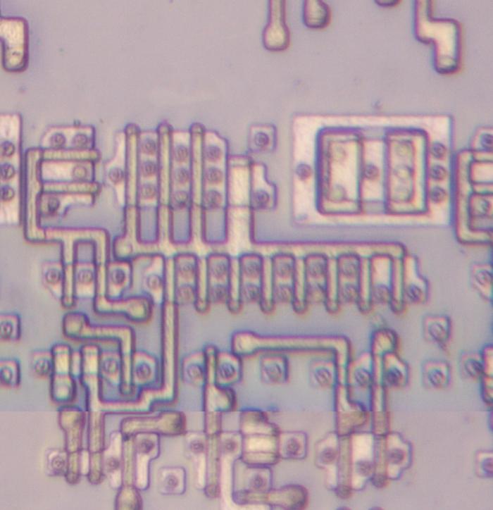
In this section, I'll show how the Pentium is constructed from layers. The bottom layer of the chip consists of transistors fabricated on the silicon die. Regions of silicon are doped with impurities to change the electrical properties; these regions appear pinkish in the photo below, compared to the grayish undoped silicon. Thin polysilicon wiring is formed on top of the silicon. Where a polysilicon line crosses doped silicon, a transistor is formed; the polysilicon creates the transistor's gate. Most of these transistors are NMOS and PMOS transistors, but there is a bipolar transistor near the upper right, the large box-like structure. The dark circles are contacts, regions where the metal layer above is connected to the polysilicon or silicon to wire the circuits together.

The polysilicon and silicon layers form the Pentium's transistors. This photo shows part of the complete circuit.

The polysilicon and silicon layers form the Pentium's transistors. This photo shows part of the complete circuit.

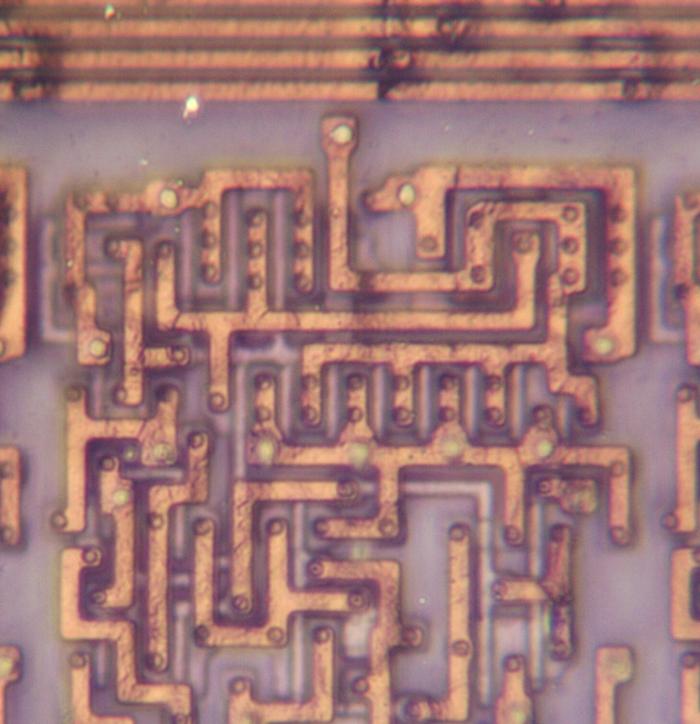
The Pentium has three layers of metal wiring. The photo below shows the bottom layer, called M1. For the most part, this layer of metal connects the transistors into various circuits, providing wiring over a short distance. The photos in this section show the same region of the chip, so you can match up features between the photos. For instance, the contacts below (black circles) match the black circles above, showing how this metal layer connects to the silicon and polysilicon circuits. You can see some of the silicon and polysilicon in this image, but most of it is hidden by the metal.

The Pentium's M1 metal layer is the bottom metal layer.

The Pentium's M1 metal layer is the bottom metal layer.

The M2 metal layer (below) sits above the M1 wiring. In this part of the chip, the M2 wires are horizontal. The thicker lines are power and ground. (Because they are thicker, they have lower resistance and can provide the necessary current to the underlying circuitry.) The thinner lines are control signals. The floating point unit is structured so functional blocks are horizontal, while data is transmitted vertically. Thus, a horizontal wire can supply a control signal to all the bits in a functional block.

The Pentium's M2 layer.

The Pentium's M2 layer.

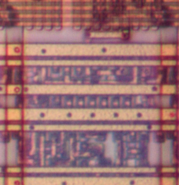
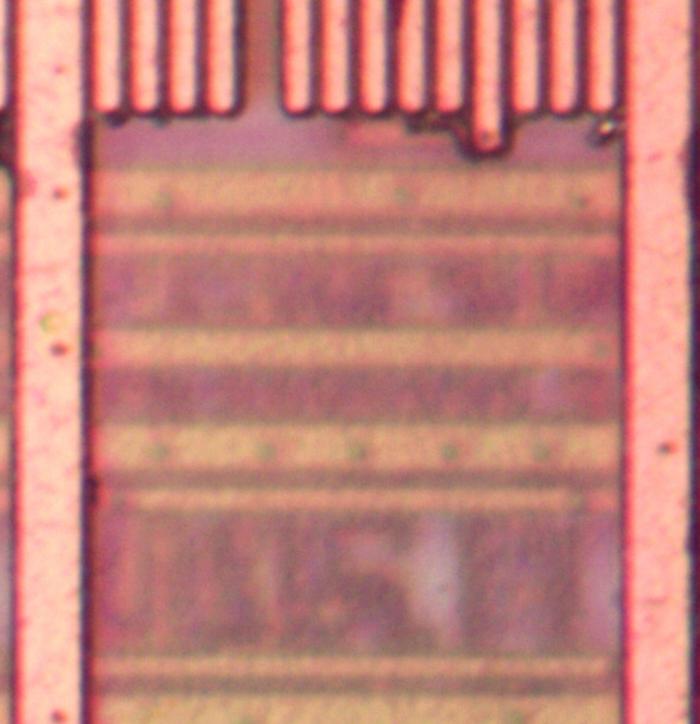
The M3 layer is the top metal layer in the Pentium. It is thicker, so it is better suited for the chip's main power and ground lines as well as long-distance bus wiring. In the photo below, the wide line on the left provides power, while the wide line on the right provides ground. The power and ground are distributed through wiring in the M2 and M1 layers until they are connected to the underlying transistors. At the top of the photo, vertical bus lines are visible; these extend for long distances through the floating point unit. Notice the slightly longer line, fourth from the right. This line provides one bit of data from the ROM, provided by the circuitry described below. The dot near the bottom is a via, connecting this line to a short wire in M2, connected to a wire in M1, connected to the silicon of the output transistors.

The Pentium's M3 metal layer. Lower layers are visible, but blurry due to the insulating oxide layers.

The Pentium's M3 metal layer. Lower layers are visible, but blurry due to the insulating oxide layers.

The circuits for the ROM's output

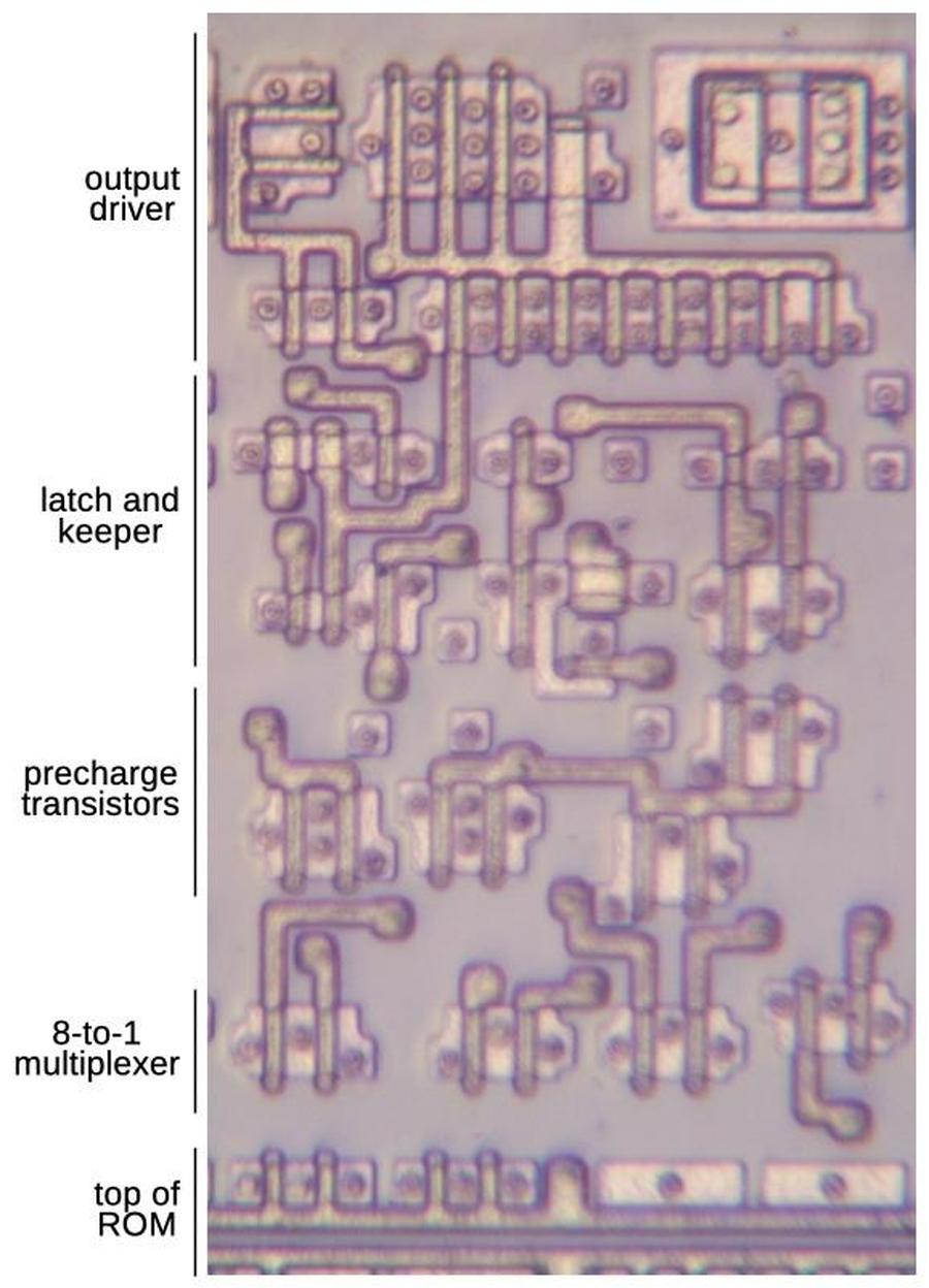
The simplified schematic below shows the circuit that I reverse-engineered. This circuit is repeated 86 times, once for each bit in the ROM's word. You might expect the ROM to provide a single 86-bit word. However, to make the layout work better, the ROM provides eight words in parallel. Thus, the circuitry must select one of the eight words with a multiplexer. In particular, each of the 86 circuits has an 8-to-1 multiplexer to select one bit out of the eight. This bit is then stored in a latch. Finally, a high-current driver amplifies the signal so it can be sent through a bus, traveling to a destination halfway across the floating point unit.

A high-level schematic of the circuit.

A high-level schematic of the circuit.

I'll provide a quick review of MOS transistors before I explain the circuitry in detail. CMOS circuitry uses two types of transistors—PMOS and NMOS—which are similar but also opposites. A PMOS transistor is turned on by a low signal on the gate, while an NMOS transistor is turned on by a high signal on the gate; the PMOS symbol has an inversion bubble on the gate. A PMOS transistor works best when pulling its output high, while an NMOS transistor works best when pulling its output low. CMOS circuitry normally uses the two types of MOS transistors in a Complementary fashion to implement logic gates, working together. What makes the circuits below interesting is that they often use NMOS and PMOS transistors independently.

The symbol for a PMOS transistor and an NMOS transistor.

The symbol for a PMOS transistor and an NMOS transistor.

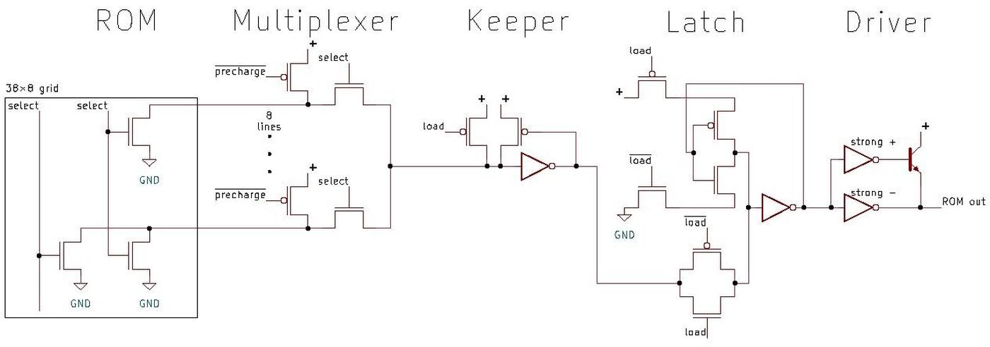
The detailed schematic below shows the circuitry at the transistor and inverter level. I'll go through each of the components in the remainder of this post.

A detailed schematic of the circuit. Click for a larger version.

A detailed schematic of the circuit. Click for a larger version.

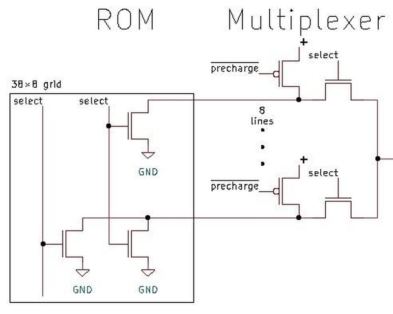
The ROM is constructed as a grid: at each grid point, the ROM can have a transistor for a 0 bit, or no transistor for a 1 bit. Thus, the data is represented by the transistor pattern. The ROM holds 304 constants so there are 304 potential transistors associated with each bit of the output word. These transistors are organized in a 38×8 grid. To select a word from the ROM, a select line activates one group of eight potential transistors. Each transistor is connected to ground, so the transistor (if present) will pull the associated line low, for a 0 bit. Note that the ROM itself consists of only NMOS transistors, making it half the size of a truly CMOS implementation. For more information on the structure and contents of the ROM, see my earlier article.

The ROM grid and multiplexer.

The ROM grid and multiplexer.

A ROM transistor can pull a line low for a 0 bit, but how does the line get pulled high for a 1 bit? This is accomplished by a precharge transistor on each line. Before a read from the ROM, the precharge transistors are all activated, pulling the lines high. If a ROM transistor is present on the line, the line will next be pulled low, but otherwise it will remain high due to the capacitance on the line.

Next, the multiplexer above selects one of the 8 lines, depending on which word is being accessed. The multiplexer consists of eight transistors. One transistor is activated by a select line, allowing the ROM's signal to pass through. The other seven transistors are in the off state, blocking those ROM signals. Thus, the multiplexer selects one of the 8 bits from the ROM.

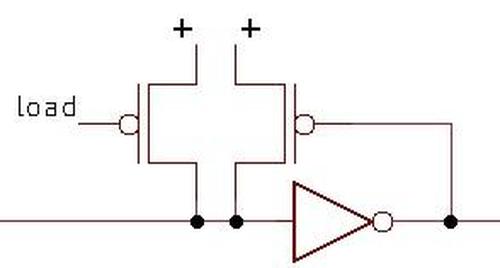
The circuit below is the "keeper." As explained above, each ROM line is charged high before reading the ROM. However, this charge can fade away. The job of the keeper is to keep the multiplexer's output high until it is pulled low. This is implemented by an inverter connected to a PMOS transistor. If the signal on the line is high, the PMOS transistor will turn on, pulling the line high. (Note that a PMOS transistor is turned on by a low signal, thus the inverter.) If the ROM pulls the line low, the transistor will turn off and stop pulling the line high. This transistor is very weak, so it is easily overpowered by the signal from the ROM. The transistor on the left ensures that the line is high at the start of the cycle.

The keeper circuit.

The keeper circuit.

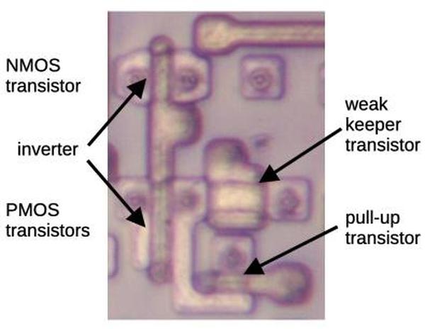
The diagram below shows the transistors for the keeper. The two transistors on the left implement a standard CMOS inverter. On the right, note the weak transistor that holds the line high. You might notice that the weak transistor looks larger and wonder why that makes the transistor weak rather than strong. The explanation is that the transistor is large in the "wrong" dimension. The current capacity of an MOS transistor is proportional to the width/length ratio of its gate. (Width is usually the long dimension and length is usually the skinny dimension.) The weak transistor's length is much larger than the other transistors, so the W/L ratio is smaller and the transistor is weaker. (You can think of the transistor's gate as a bridge between its two sides. A wide bridge with many lanes lets lots of traffic through. However, a long, single-lane bridge will slow down the traffic.)

The silicon implementation of the keeper.

The silicon implementation of the keeper.

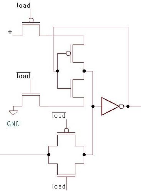
Next, we come to the latch, which remembers the value read from the ROM. This latch will read its input when the load signal is high. When the load signal goes low, the latch will hold its value. Conceptually, the latch is implemented with the circuit below. A multiplexer selects the lower input when the load signal is active, passing the latch input through to the (inverted) output. But when the load signal goes low, the multiplexer will select the top input, which is feedback of the value in the latch. This signal will cycle through the inverters and the multiplexer, holding the value until a new value is loaded. The inverters are required because the multiplexer itself doesn't provide any amplification; the signal would rapidly die out if not amplified by the inverters.

The implementation of the latch.

The implementation of the latch.

The multiplexer is implemented with two CMOS switches, one to select each multiplexer input. Each switch is a pair of PMOS and NMOS transistors that turn on together, allowing a signal to pass through. (See the bottom two transistors below.)1 The upper circuit is trickier. Conceptually, it is an inverter feeding into the multiplexer's CMOS switch. However, the order is switched so the switch feeds into the inverter. The result is not-exactly-a-switch and not-exactly-an-inverter, but the result is the same. You can also view it as an inverter with power and ground that gets cut off when not selected. I suspect this implementation uses slightly less power than the straightforward implementation.

The detailed schematic of the latch.

The detailed schematic of the latch.

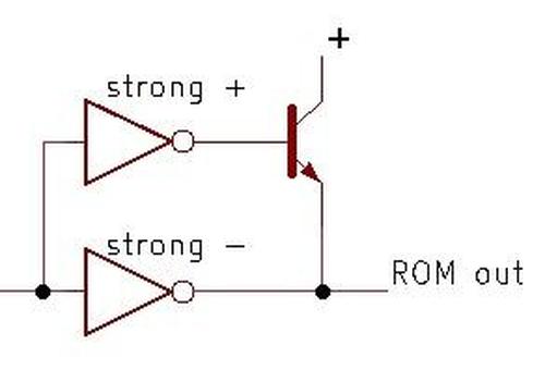
The most unusual circuit is the BiCMOS driver. By adding a few extra processing steps to the regular CMOS manufacturing process, bipolar (NPN and PNP) transistors can be created. The Pentium extensively used BiCMOS circuits since they reduced signal delays by up to 35%. Intel also used BiCMOS for the Pentium Pro, Pentium II, Pentium III, and Xeon processors. However, as chip voltages dropped, the benefit from bipolar transistors dropped too and BiCMOS was eventually abandoned.

The BiCMOS driver circuit.

The BiCMOS driver circuit.

In the Pentium, BiCMOS drivers are used when signals must travel a long distance across the chip. (In this case, the ROM output travels about halfway up the floating point unit.) These long wires have a lot of capacitance so a high-current driver circuit is needed and the NPN transistor provides extra "oomph."

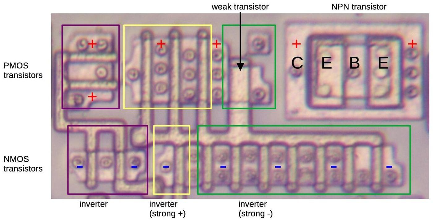
The diagram below shows how the driver is implemented. The NPN transistor is the large boxy structure in the upper right. When the base (B) is pulled high, current flows from the collector (C), pulling the emitter (E) high and thus rapidly pulling the output high. The remainder of the circuit consists of three inverters, each composed of PMOS and NMOS transistors. When a polysilicon line crosses doped silicon, it creates a transistor gate, so each crossing corresponds to a transistor. The inverters use multiple transistors in parallel to provide more current; the transistor sources and/or drains overlap to make the circuitry more compact.

This diagram shows the silicon and polysilicon for the driver circuit.

This diagram shows the silicon and polysilicon for the driver circuit.

One interesting thing about this circuit is that each inverter is carefully designed to provide the desired current, with a different current for a high output versus a low output. The first transistor (purple boxes) has two PMOS transistors and two NMOS transistors, so it is a regular inverter, balanced for high and low outputs. (This inverter is conceptually part of the latch.) The second inverter (yellow boxes) has three large PMOS transistors and one smaller NMOS transistor, so it has more ability to pull the output high than low. This transistor turns on the NPN transistor by providing a high signal to the base, so it needs more current in the high state. The third inverter (green boxes) has one weak PMOS transistor and seven NMOS transistors, so it can pull its output low strongly, but can barely pull its output high. This transistor pulls the ROM output line low, so it needs enough current to drive the entire bus line. But this transistor doesn't need to pull the output high—that's the job of the NPN transistor—so the PMOS transistor can be weak. The construction of the weak transistor is similar to the keeper's weak transistor; its gate length is much larger than the other transistors, so it provides less current.

Conclusions

The diagram below shows how the functional blocks are arranged in the complete circuit, from the ROM at the bottom to the output at the top. The floating point unit is constructed with a constant width for each bit—38.5 µm—so the circuitry is designed to fit into this width. The layout of this circuitry was hand-optimized to fit as tightly as possible, In comparison, much of the Pentium's circuitry was arranged by software using a standard-cell approach, which is much easier to design but not as dense. Since each bit in the floating point unit is repeated many times, hand-optimization paid off here.

The silicon and polysilicon of the circuit, showing the functional blocks.

The silicon and polysilicon of the circuit, showing the functional blocks.

This circuit contains 47 transistors. Since it is duplicated once for each bit, it has 4042 transistors in total, a tiny fraction of the Pentium's 3.1 million transistors. In comparison, the MOS 6502 processor has about 3500-4500 transistors, depending on how you count. In other words, the circuit to select a word from the Pentium's ROM is about as complex as the entire 6502 processor. This illustrates the dramatic growth in processor complexity described by Moore's law.

I plan to write more about the Pentium so follow me on Bluesky (@righto.com) or RSS for updates. (I'm no longer on Twitter.) You might enjoy reading about the Pentium Navajo rug.

Notes

  1. The 8-to-1 multiplexer and the latch's multiplexer use different switch implementations: the first is built from NMOS transistors while the second is built from paired PMOS and NMOS transistors. The reason is that NMOS transistors are better at pulling signals slow, while PMOS transistors are better at pulling signals high. Combining the transistors creates a switch that passes low and high signals efficiently, which is useful in the latch. The 8-to-1 multiplexer, however, only needs to pull signals low (due to the precharging), so the NMOS-only multiplexer works in this role. (Note that early NMOS processors like the 6502 and 8086 built multiplexers and pass-transistor logic out of solely NMOS. This illustrates that you can use NMOS-only switches with both logic levels, but performance is better if you add PMOS transistors.) 

Reverse-engineering a carry-lookahead adder in the Pentium

Addition is harder than you'd expect, at least for a computer. Computers use multiple types of adder circuits with different tradeoffs of size versus speed. In this article, I reverse-engineer an 8-bit adder in the Pentium's floating point unit. This adder turns out to be a carry-lookahead adder, in particular, a type known as "Kogge-Stone."1 In this article, I'll explain how a carry-lookahead adder works and I'll show how the Pentium implemented it. Warning: lots of Boolean logic ahead.

The Pentium die, showing the adder. Click this image (or any other) for a larger version.

The Pentium die, showing the adder. Click this image (or any other) for a larger version.

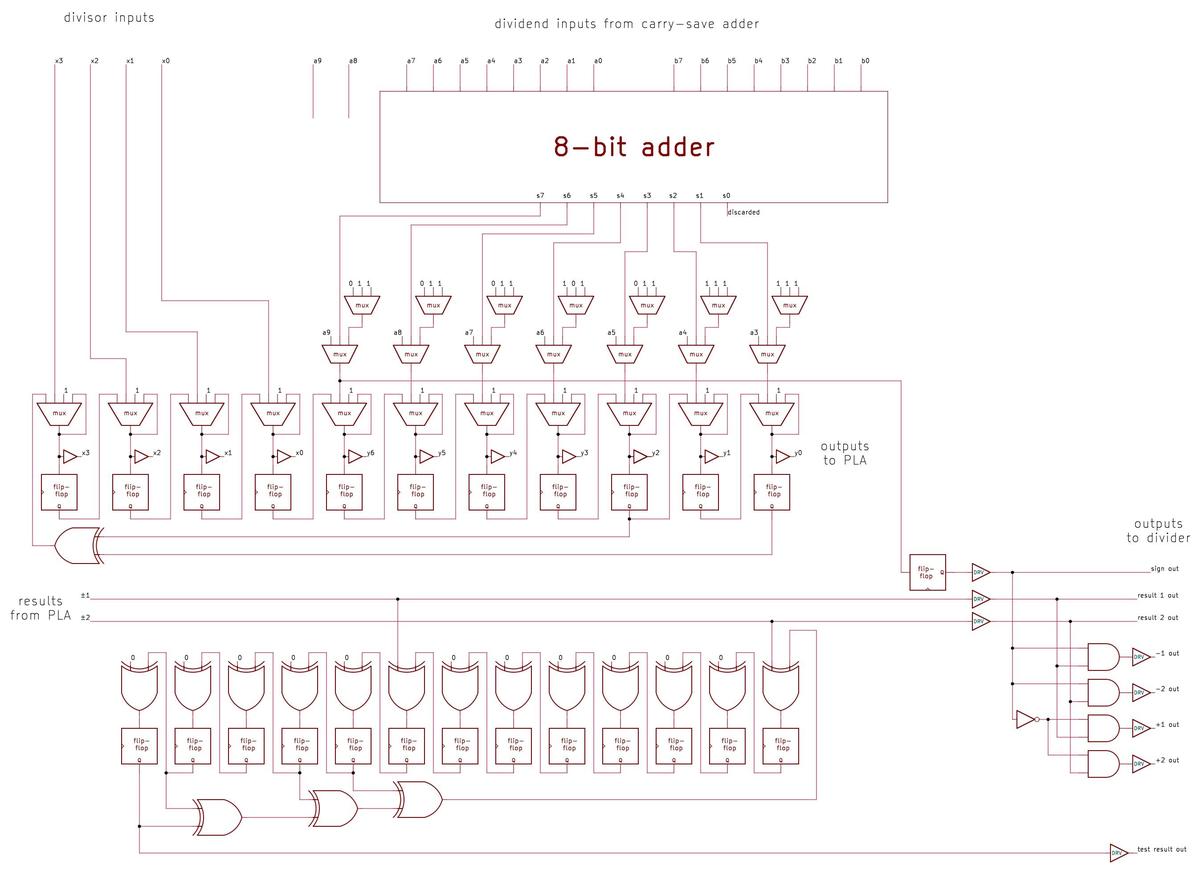
The die photo above shows the main functional units of the Pentium. The adder, in the lower right, is a small component of the floating point unit. It is not a general-purpose adder, but is used only for determining quotient digits during division. It played a role in the famous Pentium FDIV division bug, which I wrote about here.

The hardware implementation

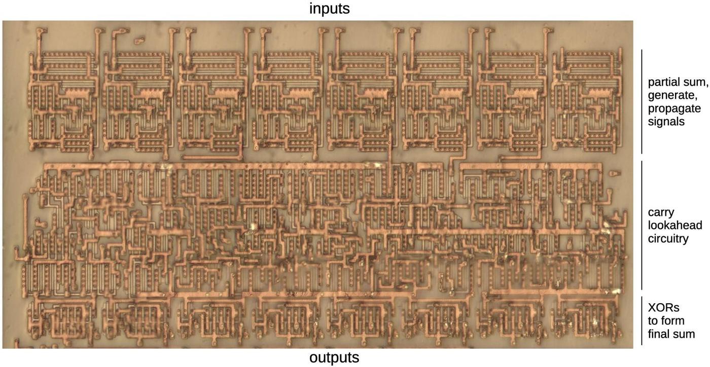
The photo below shows the carry-lookahead adder used by the divider. The adder itself consists of the circuitry highlighted in red. At the top, logic gates compute signals in parallel for each of the 8 pairs of inputs: partial sum, carry generate, and carry propagate. Next, the complex carry-lookahead logic determines in parallel if there will be a carry at each position. Finally, XOR gates apply the carry to each bit. Note that the sum/generate/propagate circuitry consists of 8 repeated blocks, and the same with the carry XOR circuitry. The carry lookahead circuitry, however, doesn't have any visible structure since it is different for each bit.2

The carry-lookahead adder that feeds the lookup table. This block of circuitry is just above the PLA on the die. I removed the metal layers, so this photo shows the doped silicon (dark) and the polysilicon (faint gray).

The carry-lookahead adder that feeds the lookup table. This block of circuitry is just above the PLA on the die. I removed the metal layers, so this photo shows the doped silicon (dark) and the polysilicon (faint gray).

The large amount of circuitry in the middle is used for testing; see the footnote.3 At the bottom, the drivers amplify control signals for various parts of the circuit.

The carry-lookahead adder concept

The problem with addition is that carries make addition slow. Consider calculating 99999+1 by hand. You'll start with 9+1=10, then carry the one, generating another carry, which generates another carry, and so forth, until you go through all the digits. Computer addition has the same problem: If you're adding two numbers, the low-order bits can generate a carry that then propagates through all the bits. An adder that works this way—known as a ripple carry adder—will be slow because the carry has to ripple through all the bits. As a result, CPUs use special circuits to make addition faster.

One solution is the carry-lookahead adder. In this adder, all the carry bits are computed in parallel, before computing the sums. Then, the sum bits can be computed in parallel, using the carry bits. As a result, the addition can be completed quickly, without waiting for the carries to ripple through the entire sum.

It may seem impossible to compute the carries without computing the sum first, but there's a way to do it. For each bit position, you determine signals called "carry generate" and "carry propagate". These signals can then be used to determine all the carries in parallel. The generate signal indicates that the position generates a carry. For instance, if you add binary 1xx and 1xx (where x is an arbitrary bit), a carry will be generated from the top bit, regardless of the unspecified bits. On the other hand, adding 0xx and 0xx will never produce a carry. Thus, the generate signal is produced for the first case but not the second.

But what about 1xx plus 0xx? We might get a carry, for instance, 111+001, but we might not get a carry, for instance, 101+001. In this "maybe" case, we set the carry propagate signal, indicating that a carry into the position will get propagated out of the position. For example, if there is a carry out of the middle position, 1xx+0xx will have a carry from the top bit. But if there is no carry out of the middle position, then there will not be a carry from the top bit. In other words, the propagate signal indicates that a carry into the top bit will be propagated out of the top bit.

To summarize, adding 1+1 will generate a carry. Adding 0+1 or 1+0 will propagate a carry. Thus, the generate signal is formed at each position by Gn = An·Bn, where A and B are the inputs. The propagate signal is Pn = An+Bn, the logical-OR of the inputs.4

Now that the propagate and generate signals are defined, they can be used to compute the carry Cn at each bit position:
C1 = G0: a carry into bit 1 occurs if a carry is generated from bit 0.
C2 = G1 + G0P1: A carry into bit 2 occur if bit 1 generates a carry or bit 1 propagates a carry from bit 0.
C3 = G2 + G1P2 + G0P1P2: A carry into bit 3 occurs if bit 2 generates a carry, or bit 2 propagates a carry generated from bit 1, or bits 2 and 1 propagate a carry generated from bit 0.
C4 = G3 + G2P3 + G1P2P3 + G0P1P2P3: A carry into bit 4 occurs if a carry is generated from bit 3, 2, 1, or 0 along with the necessary propagate signals.
... and so forth, getting more complicated with each bit ...

The important thing about these equations is that they can be computed in parallel, without waiting for a carry to ripple through each position. Once each carry is computed, the sum bits can be computed in parallel: Sn = An ⊕ Bn ⊕ Cn. In other words, the two input bits and the computed carry are combined with exclusive-or.

Implementing carry lookahead with a parallel prefix adder

The straightforward way to implement carry lookahead is to directly implement the equations above. However, this approach requires a lot of circuitry due to the complicated equations. Moreover, it needs gates with many inputs, which are slow for electrical reasons.5

The Pentium's adder implements the carry lookahead in a different way, called the "parallel prefix adder."7 The idea is to produce the propagate and generate signals across ranges of bits, not just single bits as before. For instance, the propagate signal P32 indicates that a carry in to bit 2 would be propagated out of bit 3. And G30 indicates that bits 3 to 0 generate a carry out of bit 3.

Using some mathematical tricks,6 you can take the P and G values for two smaller ranges and merge them into the P and G values for the combined range. For instance, you can start with the P and G values for bits 0 and 1, and produce P10 and G10. These could be merged with P32 and G32 to produce P30 and G30, indicating if a carry is propagated across bits 3-0 or generated by bits 3-0. Note that Gn0 is the carry-lookahead value we need for bit n, so producing these G values gives the results that we need from the carry-lookahead implementation.

This merging process is more efficient than the "brute force" implementation of the carry-lookahead logic since logic subexpressions can be reused. This merging process can be implemented in many ways, including Kogge-Stone, Brent-Kung, and Ladner-Fischer. The different algorithms have different tradeoffs of performance versus circuit area. In the next section, I'll show how the Pentium implements the Kogge-Stone algorithm.

The Pentium's implementation of the carry-lookahead adder

The Pentium's adder is implemented with four layers of circuitry. The first layer produces the propagate and generate signals (P and G) for each bit, along with a partial sum (the sum without any carries). The second layer merges pairs of neighboring P and G values, producing, for instance G65 and P21. The third layer generates the carry-lookahead bits by merging previous P and G values. This layer is complicated because it has different circuitry for each bit. Finally, the fourth layer applies the carry bits to the partial sum, producing the final arithmetic sum.

Here is the schematic of the adder, from my reverse engineering. The circuit in the upper left is repeated 8 times to produce the propagate, generate, and partial sum for each bit. This corresponds to the first layer of logic. At the left are the circuits to merge the generate and propagate signals across pairs of bits. These circuits are the second layer of logic.

Schematic of the Pentium's 8-bit carry-lookahead adder. Click for a larger version.

Schematic of the Pentium's 8-bit carry-lookahead adder. Click for a larger version.

The circuitry at the right is the interesting part—it computes the carries in parallel and then computes the final sum bits using XOR. This corresponds to the third and fourth layers of circuitry respectively. The circuitry gets more complicated going from bottom to top as the bit position increases.

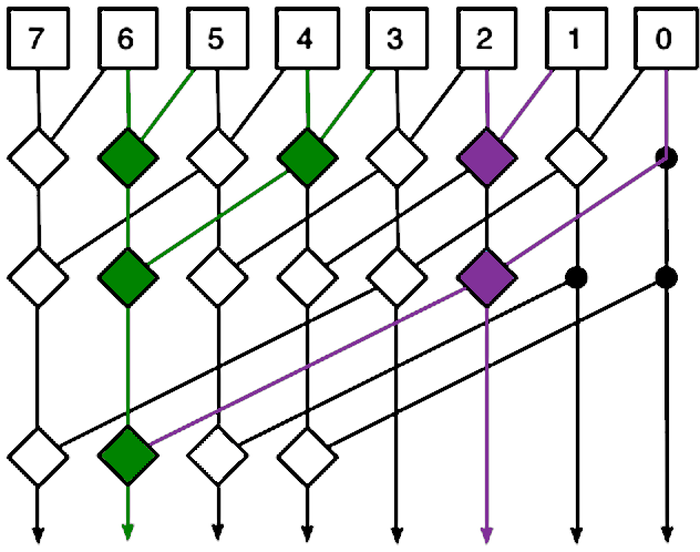
The diagram below is the standard diagram that illustrates how a Kogge-Stone adder works. It's rather abstract, but I'll try to explain it. The diagram shows how the P and G signals are merged to produce each output at the bottom. Each line coresponds to both the P and the G signal. Each square box generates the P and G signals for that bit. (Confusingly, the vertical and diagonal lines have the same meaning, indicating inputs going into a diamond and outputs coming out of a diamond.) Each diamond combines two ranges of P and G signals to generate new P and G signals for the combined range. Thus, the signals cover wider ranges as they progress downward, ending with the Gn0 signals that are the outputs.

A diagram of an 8-bit Kogge-Stone adder highlighting the carry out of bit 6 (green) and out of bit 2 (purple). Modification of the diagram by Robey Pointer, Wikimedia Commons.

A diagram of an 8-bit Kogge-Stone adder highlighting the carry out of bit 6 (green) and out of bit 2 (purple). Modification of the diagram by Robey Pointer, Wikimedia Commons.

It may be easier to understand the diagram by starting with the outputs. I've highlighted two circuits: The purple circuit computes the carry into bit 3 (out of bit 2), while the green circuit computes the carry into bit 7 (out of bit 6). Following the purple output upward, note that it forms a tree reaching bits 2, 1, and 0, so it generates the carry based on these bits, as desired. In more detail, the upper purple diamond combines the P and G signals for bits 2 and 1, generating P21 and G21. The lower purple diamond merges in P0 and G0 to create P20 and G20. Signal G20 indicates of bits 2 through 0 generate a carry; this is the desired carry value into bit 3.

Now, look at the green output and see how it forms a tree going upward, combining bits 6 through 0. Notice how it takes advantage of the purple carry output, reducing the circuitry required. It also uses P65, P43, and the corresponding G signals. Comparing with the earlier schematic shows how the diagram corresponds to the schematic, but abstracts out the details of the gates.

Comparing the diagram to the schematic, each square box corresponds to to the circuit in the upper left of the schematic that generates P and G, the first layer of circuitry. The first row of diamonds corresponds to the pairwise combination circuitry on the left of the schematic, the second layer of circuitry. The remaining diamonds correspond to the circuitry on the right of the schematic, with each column corresponding to a bit, the third layer of circuitry. (The diagram ignores the final XOR step, the fourth layer of circuitry.)

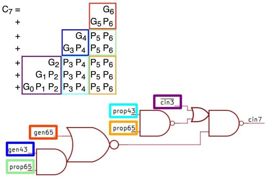
Next, I'll show how the diagram above, the logic equations, and the schematic are related. The diagram below shows the logic equation for C7 and how it is implemented with gates; this corresponds to the green diamonds above. The gates on the left below computes G63; this corresponds to the middle green diamond on the left. The next gate below computes P63 from P65 and P43; this corresponds to the same green diamond. The last gates mix in C3 (the purple line above); this corresponds to the bottom green diamond. As you can see, the diamonds abstract away the complexity of the gates. Finally, the colored boxes below show how the gate inputs map onto the logic equation. Each input corresponds to multiple terms in the equation (6 inputs replace 28 terms), showing how this approach reduces the circuitry required.

This diagram shows how the carry into bit 7 is computed, comparing the equations to the logic circuit.

This diagram shows how the carry into bit 7 is computed, comparing the equations to the logic circuit.

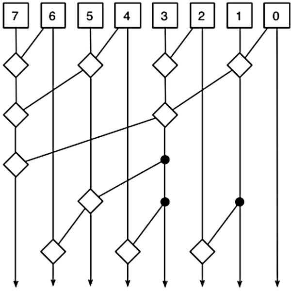
There are alternatives to the Kogge-Stone adder. For example, a Brent-Kung adder (below) uses a different arrangement with fewer diamonds but more layers. Thus, a Brent-Kung adder uses less circuitry but is slower. (You can follow each output upward to verify that the tree reaches the correct inputs.)

A diagram of an 8-bit Brent-Kung adder. Diagram by Robey Pointer, Wikimedia Commons.

A diagram of an 8-bit Brent-Kung adder. Diagram by Robey Pointer, Wikimedia Commons.

Conclusions

The photo below shows the adder circuitry. I've removed the top two layers of metal, leaving the bottom layer of metal. Underneath the metal, polysilicon wiring and doped silicon regions are barely visible; they form the transistors. At the top are eight blocks of gates to generate the partial sum, generate, and propagate signals for each bit. (This corresponds to the first layer of circuitry as described earlier.) In the middle is the carry lookahead circuitry. It is irregular since each bit has different circuitry. (This corresponds to the second and third layers of circuitry, jumbled together.) At the bottom, eight XOR gates combine the carry lookahead output with the partial sum to produce the adder's output. (This corresponds to the fourth layer of circuitry.)

The Pentium's adder circuitry with the top two layers of metal removed.

The Pentium's adder circuitry with the top two layers of metal removed.

The Pentium uses many adders for different purposes: in the integer unit, in the floating point unit, and for address calculation, among others. Floating-point division is known to use a carry-save adder to hold the partial remainder at each step; see my post on the Pentium FDIV division bug for details. I don't know what types of adders are used in other parts of the chip, but maybe I'll reverse-engineer some of them. Follow me on Bluesky (@righto.com) or RSS for updates. (I'm no longer on Twitter.)

Footnotes and references

  1. Strangely, the original paper by Kogge and Stone had nothing to do with addition and carries. Their 1973 paper was titled, "A Parallel Algorithm for the Efficient Solution of a General Class of Recurrence Equations." It described how to solve recurrence problems on parallel computers, in particular the massively parallel ILLIAC IV. As far as I can tell, it wasn't until 1987 that their algorithm was applied to carry lookahead, in Fast Area-Efficient VLSI Adders

  2. I'm a bit puzzled why the circuit uses an 8-bit carry-lookahead adder since only 7 bits are used. Moreover, the carry-out is unused. However, the adder's bottom output bit is not connected to anything. Perhaps the 8-bit adder was a standard logic block at Intel and was used as-is. 

  3. I probably won't make a separate blog post on the testing circuitry, so I'll put details in this footnote. Half of the circuitry in the adder block is used to test the lookup table. The reason is that a chip such as the Pentium is very difficult to test: if one out of 3.1 million transistors goes bad, how do you detect it? For a simple processor like the 8080, you can run through the instruction set and be fairly confident that any problem would turn up. But with a complex chip, it is almost impossible to come up with an instruction sequence that would test every bit of the microcode ROM, every bit of the cache, and so forth. Starting with the 386, Intel added circuitry to the processor solely to make testing easier; about 2.7% of the transistors in the 386 were for testing.

    To test a ROM inside the processor, Intel added circuitry to scan the entire ROM and checksum its contents. Specifically, a pseudo-random number generator runs through each address, while another circuit computes a checksum of the ROM output, forming a "signature" word. At the end, if the signature word has the right value, the ROM is almost certainly correct. But if there is even a single bit error, the checksum will be wrong and the chip will be rejected. The pseudo-random numbers and the checksum are both implemented with linear feedback shift registers (LFSR), a shift register along with a few XOR gates to feed the output back to the input. For more information on testing circuitry in the 386, see Design and Test of the 80386, written by Pat Gelsinger, who became Intel's CEO years later. Even with the test circuitry, 48% of the transistor sites in the 386 were untested. The instruction-level test suite to test the remaining circuitry took almost 800,000 clock cycles to run. The overhead of the test circuitry was about 10% more transistors in the blocks that were tested.

    In the Pentium, the circuitry to test the lookup table PLA is just below the 7-bit adder. An 11-bit LFSR creates the 11-bit input value to the lookup table. A 13-bit LFSR hashes the two-bit quotient result from the PLA, forming a 13-bit checksum. The checksum is fed serially to test circuitry elsewhere in the chip, where it is merged with other test data and written to a register. If the register is 0 at the end, all the tests pass. In particular, if the checksum is correct, you can be 99.99% sure that the lookup table is operating as expected. The ironic thing is that this test circuit was useless for the FDIV bug: it ensured that the lookup table held the intended values, but the intended values were wrong.

    Why did Intel generate test addresses with a pseudo-random sequence instead of a sequential counter? It turns out that a linear feedback shift register (LFSR) is slightly more compact than a counter. This LFSR trick was also used in a touch-tone chip and the program counter of the Texas Instruments TMS 1000 microcontroller (1974). In the TMS 1000, the program counter steps through the program pseudo-randomly rather than sequentially. The program is shuffled appropriately in the ROM to counteract the sequence, so the program executes as expected and a few transistors are saved.

    Block diagram of the testing circuitry.

    Block diagram of the testing circuitry.

  4. The bits 1+1 will set generate, but should propagate be set too? It doesn't make a difference as far as the equations. This adder sets propagate for 1+1 but some other adders do not. The answer depends on if you use an inclusive-or or exclusive-or gate to produce the propagate signal. 

  5. One solution is to implement the carry-lookahead circuit in blocks of four. This can be scaled up with a second level of carry-lookahead to provide the carry lookahead across each group of four blocks. A third level can provide carry lookahead for groups of four second-level blocks, and so forth. This approach requires O(log(N)) levels for N-bit addition. This approach is used by the venerable 74181 ALU, a chip used by many minicomputers in the 1970s; I reverse-engineered the 74181 here. The 74182 chip provides carry lookahead for the higher levels. 

  6. I won't go into the mathematics of merging P and G signals; see, for example, Adder Circuits, Adders, or Carry Lookahead Adders for additional details. The important factor is that the carry merge operator is associative (actually a monoid), so the sub-ranges can be merged in any order. This flexibility is what allows different algorithms with different tradeoffs. 

  7. The idea behind a prefix adder is that we want to see if there is a carry out of bit 0, bits 0-1, bits 0-2, bits 0-3, 0-4, and so forth. These are all the prefixes of the word. Since the prefixes are computed in parallel, it's called a parallel prefix adder. 

Pi in the Pentium: reverse-engineering the constants in its floating-point unit

Intel released the powerful Pentium processor in 1993, establishing a long-running brand of high-performance processors.1 The Pentium includes a floating-point unit that can rapidly compute functions such as sines, cosines, logarithms, and exponentials. But how does the Pentium compute these functions? Earlier Intel chips used binary algorithms called CORDIC, but the Pentium switched to polynomials to approximate these transcendental functions much faster. The polynomials have carefully-optimized coefficients that are stored in a special ROM inside the chip's floating-point unit. Even though the Pentium is a complex chip with 3.1 million transistors, it is possible to see these transistors under a microscope and read out these constants. The first part of this post discusses how the floating point constant ROM is implemented in hardware. The second part explains how the Pentium uses these constants to evaluate sin, log, and other functions.

The photo below shows the Pentium's thumbnail-sized silicon die under a microscope. I've labeled the main functional blocks; the floating-point unit is in the lower right. The constant ROM (highlighted) is at the bottom of the floating-point unit. Above the floating-point unit, the microcode ROM holds micro-instructions, the individual steps for complex instructions. To execute an instruction such as sine, the microcode ROM directs the floating-point unit through dozens of steps to compute the approximation polynomial using constants from the constant ROM.
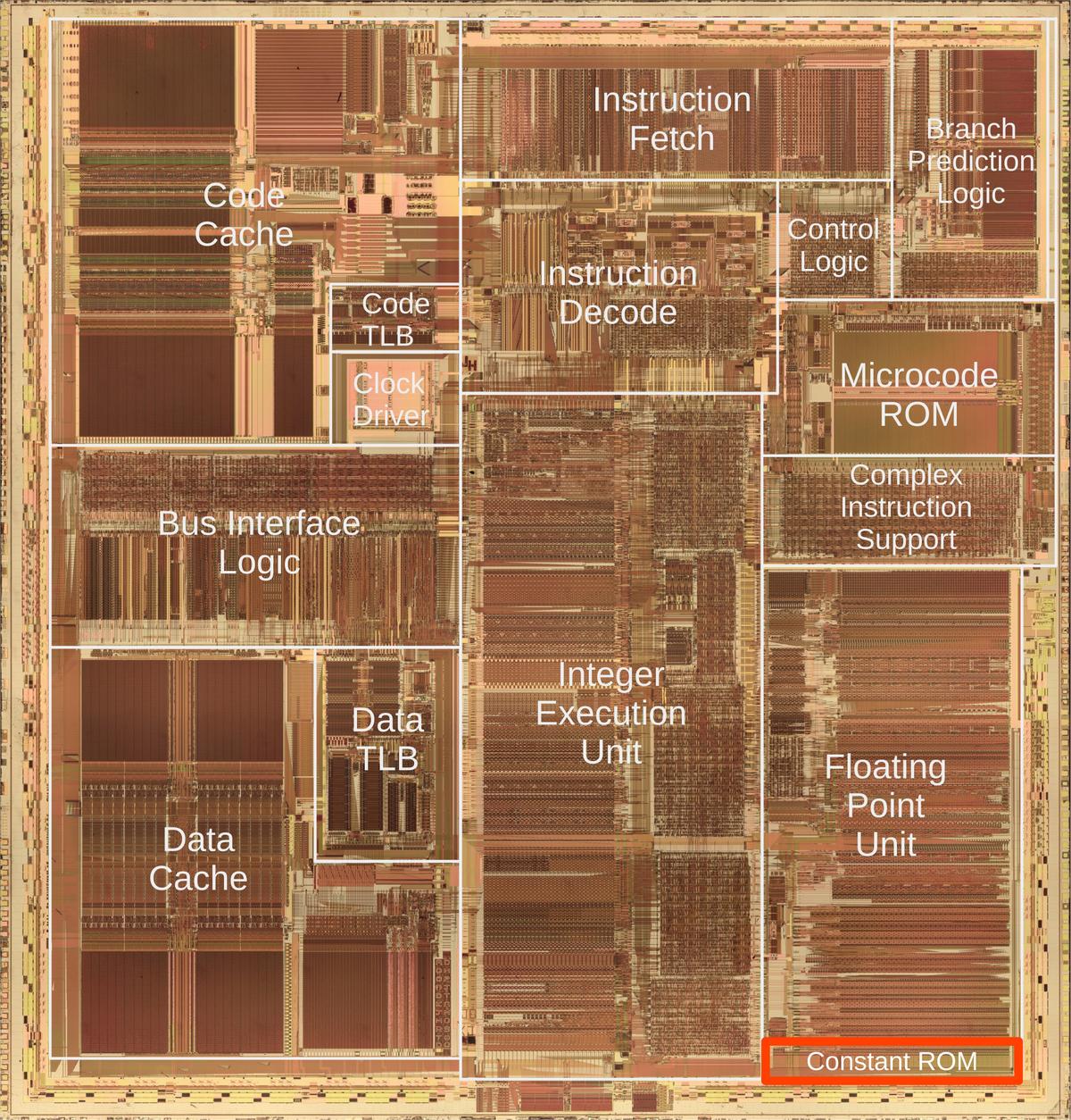
Die photo of the Intel Pentium processor with the floating point constant ROM highlighted in red. Click this image (or any other) for a larger version.

Die photo of the Intel Pentium processor with the floating point constant ROM highlighted in red. Click this image (or any other) for a larger version.

Finding pi in the constant ROM

In binary, pi is 11.00100100001111110... but what does this mean? To interpret this, the value 11 to the left of the binary point is simply 3 in binary. (The "binary point" is the same as a decimal point, except for binary.) The digits to the right of the binary point have the values 1/2, 1/4, 1/8, and so forth. Thus, the binary value `11.001001000011... corresponds to 3 + 1/8 + 1/64 + 1/4096 + 1/8192 + ..., which matches the decimal value of pi. Since pi is irrational, the bit sequence is infinite and non-repeating; the value in the ROM is truncated to 67 bits and stored as a floating point number.

A floating point number is represented by two parts: the exponent and the significand. Floating point numbers include very large numbers such as 6.02×10²³ and very small numbers such as 1.055×10⁻³⁴. In decimal, 6.02×10²³ has a significand (or mantissa) of 6.02, multiplied by a power of 10 with an exponent of 23. In binary, a floating point number is represented similarly, with a significand and exponent, except the significand is multiplied by a power of 2 rather than 10. For example, pi is represented in floating point as 1.1001001...×21.

The diagram below shows how pi is encoded in the Pentium chip. Zooming in shows the constant ROM. Zooming in on a small part of the ROM shows the rows of transistors that store the constants. The arrows point to the transistors representing the bit sequence 11001001, where a 0 bit is represented by a transistor (vertical white line) and a 1 bit is represented by no transistor (solid dark silicon). Each magnified black rectangle at the bottom has two potential transistors, storing two bits. The key point is that by looking at the pattern of stripes, we can determine the pattern of transistors and thus the value of each constant, pi in this case.
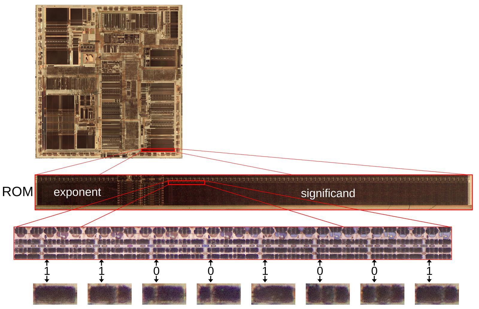
A portion of the floating-point ROM, showing the value of pi. Click this image (or any other) for a larger version.

A portion of the floating-point ROM, showing the value of pi. Click this image (or any other) for a larger version.

The bits are spread out because each row of the ROM holds eight interleaved constants to improve the layout. Above the ROM bits, multiplexer circuitry selects the desired constant from the eight in the activated row. In other words, by selecting a row and then one of the eight constants in the row, one of the 304 constants in the ROM is accessed. The ROM stores many more digits of pi than shown here; the diagram shows 8 of the 67 significand bits.

Implementation of the constant ROM

The ROM is built from MOS (metal-oxide-semiconductor) transistors, the transistors used in all modern computers. The diagram below shows the structure of an MOS transistor. An integrated circuit is constructed from a silicon substrate. Regions of the silicon are doped with impurities to create "diffusion" regions with desired electrical properties. The transistor can be viewed as a switch, allowing current to flow between two diffusion regions called the source and drain. The transistor is controlled by the gate, made of a special type of silicon called polysilicon. Applying voltage to the gate lets current flow between the source and drain, which is otherwise blocked. Most computers use two types of MOS transistors: NMOS and PMOS. The two types have similar construction but reverse the doping; NMOS uses n-type diffusion regions as shown below, while PMOS uses p-type diffusion regions. Since the two types are complementary (C), circuits built with the two types of transistors are called CMOS.
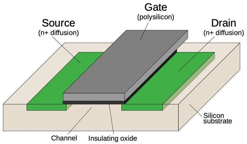
Structure of a MOSFET in an integrated circuit.

Structure of a MOSFET in an integrated circuit.

The image below shows how a transistor in the ROM looks under the microscope. The pinkish regions are the doped silicon that forms the transistor's source and drain. The vertical white line is the polysilicon that forms the transistor's gate. For this photo, I removed the chip's three layers of metal, leaving just the underlying silicon and the polysilicon. The circles in the source and drain are tungsten contacts that connect the silicon to the metal layer above.

One transistor in the constant ROM.

One transistor in the constant ROM.

The diagram below shows eight bits of storage. Each of the four pink silicon rectangles has two potential transistors. If a polysilicon gate crosses the silicon, a transistor is formed; otherwise there is no transistor. When a select line (horizontal polysilicon) is energized, it will turn on all the transistors in that row. If a transistor is present, the corresponding ROM bit is 0 because the transistor will pull the output line to ground. If a transistor is absent, the ROM bit is 1. Thus, the pattern of transistors determines the data stored in the ROM. The ROM holds 26144 bits (304 words of 86 bits) so it has 26144 potential transistors.

Eight bits of storage in the ROM.

Eight bits of storage in the ROM.

The photo below shows the bottom layer of metal (M1): vertical metal wires that provide the ROM outputs and supply ground to the ROM. (These wires are represented by gray lines in the schematic above.) The polysilicon transistors (or gaps as appropriate) are barely visible between the metal lines. Most of the small circles are tungsten contacts to the silicon or polysilicon; compare with the photo above. Other circles are tungsten vias to the metal layer on top (M2), horizontal wiring that I removed for this photo. The smaller metal "tabs" act as jumpers between the horizontal metal select lines in M2 and the polysilicon select lines. The top metal layer (M3, not visible) has thicker vertical wiring for the chip's primary distribution power and ground. Thus, the three metal layers alternate between horizontal and vertical wiring, with vias between the layers.
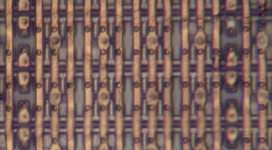
A closeup of the ROM showing the bottom metal layer.

A closeup of the ROM showing the bottom metal layer.

The ROM is implemented as two grids of cells (below): one to hold exponents and one to hold significands, as shown below. The exponent grid (on the left) has 38 rows and 144 columns of transistors, while the significand grid (on the right) has 38 rows and 544 columns. To make the layout work better, each row holds eight different constants; the bits are interleaved so the ROM holds the first bit of eight constants, then the second bit of eight constants, and so forth. Thus, with 38 rows, the ROM holds 304 constants; each constant has 18 bits in the exponent part and 68 bits in the significand section.

A diagram of the constant ROM and supporting circuitry. Most of the significand ROM has been cut out to make it fit.

A diagram of the constant ROM and supporting circuitry. Most of the significand ROM has been cut out to make it fit.

The exponent part of each constant consists of 18 bits: a 17-bit exponent and one bit for the sign of the significand and thus the constant. There is no sign bit for the exponent because the exponent is stored with 65535 (0x0ffff) added to it, avoiding negative values. The 68-bit significand entry in the ROM consists of a mysterious flag bit2 followed by the 67-bit significand; the first bit of the significand is the integer part and the remainder is the fractional part.3 The complete contents of the ROM are in the appendix at the bottom of this post.

To select a particular constant, the "row select" circuitry between the two sections activates one of the 38 rows. That row provides 144+544 bits to the selection circuitry above the ROM. This circuitry has 86 multiplexers; each multiplexer selects one bit out of the group of 8, selecting the desired constant. The significand bits flow into the floating-point unit datapath circuitry above the ROM. The exponent circuitry, however, is in the upper-left corner of the floating-point unit, a considerable distance from the ROM, so the exponent bits travel through a bus to the exponent circuitry.

The row select circuitry consists of gates to decode the row number, along with high-current drivers to energize the selected row in the ROM. The photo below shows a closeup of two row driver circuits, next to some ROM cells. At the left, PMOS and NMOS transistors implement a gate to select the row. Next, larger NMOS and PMOS transistors form part of the driver. The large square structures are bipolar NPN transistors; the Pentium is unusual because it uses both bipolar transistors and CMOS, a technique called BiCMOS.4 Each driver occupies as much height as four rows of the ROM, so there are four drivers arranged horizontally; only one is visible in the photo.
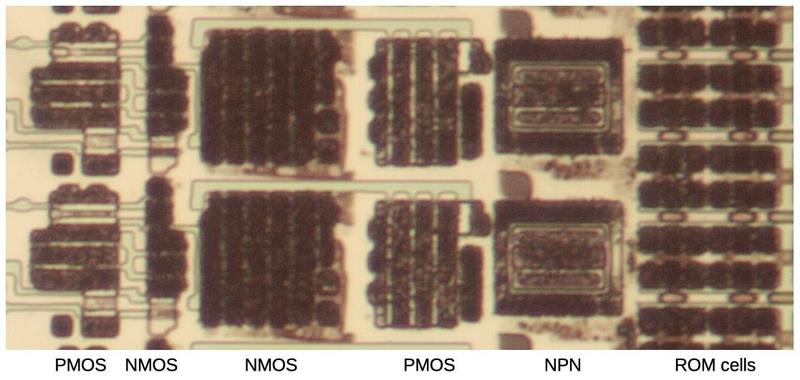
ROM drivers implemented with BiCMOS.

ROM drivers implemented with BiCMOS.

Structure of the floating-point unit

The floating-point unit is structured with data flowing vertically through horizontal functional units, as shown below. The functional units—adders, shifters, registers, and comparators—are arranged in rows. This collection of functional units with data flowing through them is called the datapath.5
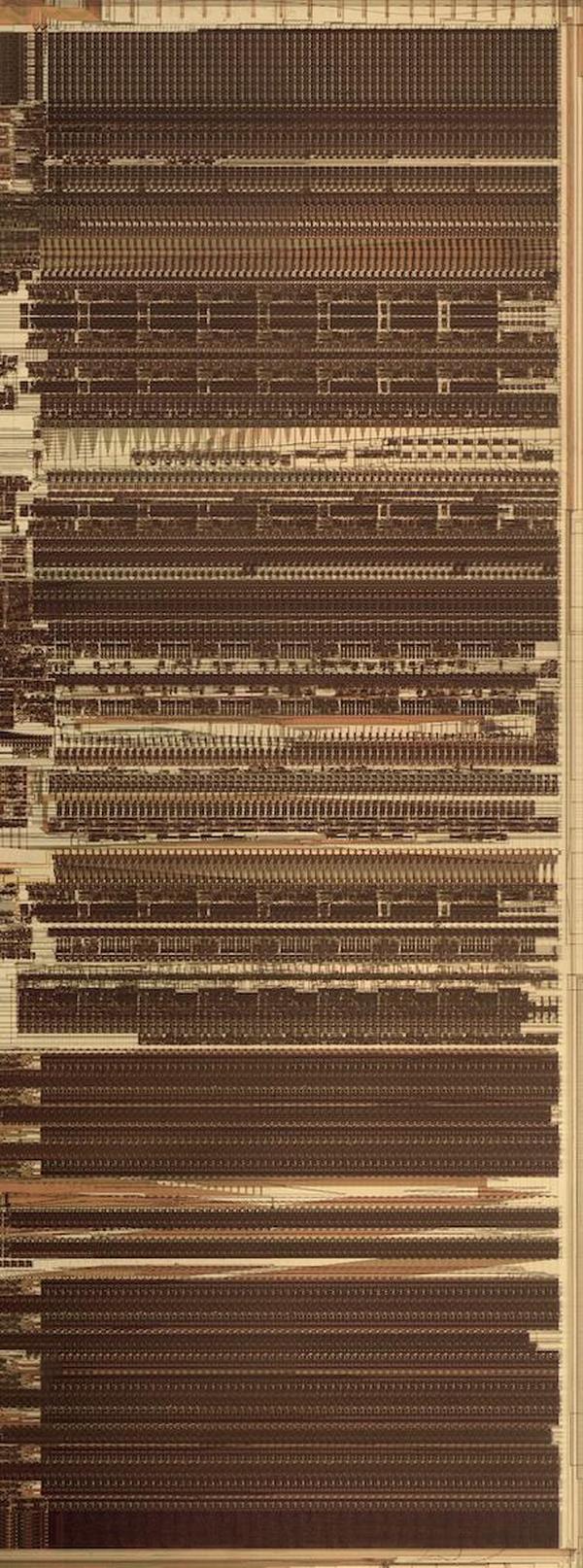
The datapath of the floating-point unit. The ROM is at the bottom.

The datapath of the floating-point unit. The ROM is at the bottom.

Each functional unit is constructed from cells, one per bit, with the high-order bit on the left and the low-order bit on the right. Each cell has the same width—38.5 µm—so the functional units can be connected like Lego blocks snapping together, minimizing the wiring. The height of a functional unit varies as needed, depending on the complexity of the circuit. Functional units typically have 69 bits, but some are wider, so the edges of the datapath circuitry are ragged.

This cell-based construction explains why the ROM has eight constants per row. A ROM bit requires a single transistor, which is much narrower than, say, an adder. Thus, putting one bit in each 38.5 µm cell would waste most of the space. Compacting the ROM bits into a narrow block would also be inefficient, requiring diagonal wiring to connect each ROM bit to the corresponding datapath bit. By putting eight bits for eight different constants into each cell, the width of a ROM cell matches the rest of the datapath and the alignment of bits is preserved. Thus, the layout of the ROM in silicon is dense, efficient, and matches the width of the rest of the floating-point unit.

Polynomial approximation: don't use a Taylor series

Now I'll move from the hardware to the constants. If you look at the constant ROM contents in the appendix, you may notice that many constants are close to reciprocals or reciprocal factorials, but don't quite match. For instance, one constant is 0.1111111089, which is close to 1/9, but visibly wrong. Another constant is almost 1/13! (factorial) but wrong by 0.1%. What's going on?

The Pentium uses polynomials to approximate transcendental functions (sine, cosine, tangent, arctangent, and base-2 powers and logarithms). Intel's earlier floating-point units, from the 8087 to the 486, used an algorithm called CORDIC that generated results a bit at a time. However, the Pentium takes advantage of its fast multiplier and larger ROM and uses polynomials instead, computing results two to three times faster than the 486 algorithm.

You may recall from calculus that a Taylor series polynomial approximates a function near a point (typically 0). For example, the equation below gives the Taylor series for sine.

Using the five terms shown above generates a function that looks indistinguishable from sine in the graph below. However, it turns out that this approximation has too much error to be useful.
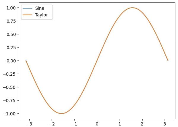
Plot of the sine function and the Taylor series approximation.

Plot of the sine function and the Taylor series approximation.

The problem is that a Taylor series is very accurate near 0, but the error soars near the edges of the argument range, as shown in the graph on the left below. When implementing a function, we want the function to be accurate everywhere, not just close to 0, so the Taylor series isn't good enough.
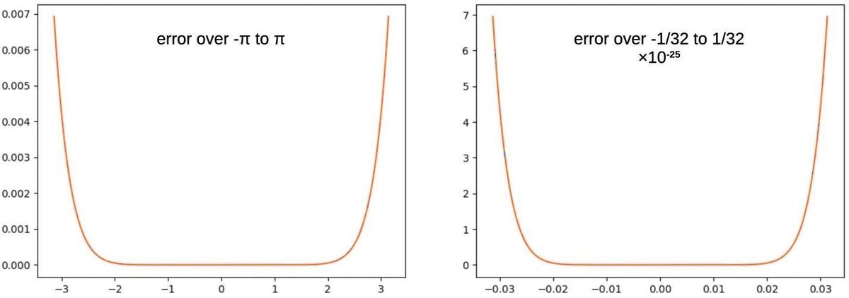
The absolute error for a Taylor-series approximation to sine (5 terms), over two different argument ranges.

The absolute error for a Taylor-series approximation to sine (5 terms), over two different argument ranges.

One improvement is called range reduction: shrinking the argument to a smaller range so you're in the accurate flat part.6 The graph on the right looks at the Taylor series over the smaller range [-1/32, 1/32]. This decreases the error dramatically, by about 22 orders of magnitude (note the scale change). However, the error still shoots up at the edges of the range in exactly the same way. No matter how much you reduce the range, there is almost no error in the middle, but the edges have a lot of error.7

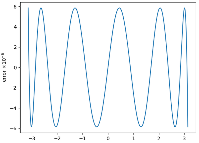
How can we get rid of the error near the edges? The trick is to tweak the coefficients of the Taylor series in a special way that will increase the error in the middle, but decrease the error at the edges by much more. Since we want to minimize the maximum error across the range (called minimax), this tradeoff is beneficial. Specifically, the coefficients can be optimized by a process called the Remez algorithm.8 As shown below, changing the coefficients by less than 1% dramatically improves the accuracy. The optimized function (blue) has much lower error over the full range, so it is a much better approximation than the Taylor series (orange).
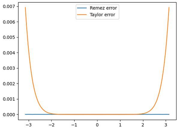
Comparison of the absolute error from the Taylor series and a Remez-optimized polynomial, both with maximum term x9. This Remez polynomial is not one from the Pentium.

Comparison of the absolute error from the Taylor series and a Remez-optimized polynomial, both with maximum term x9. This Remez polynomial is not one from the Pentium.

To summarize, a Taylor series is useful in calculus, but shouldn't be used to approximate a function. You get a much better approximation by modifying the coefficients very slightly with the Remez algorithm. This explains why the coefficients in the ROM almost, but not quite, match a Taylor series.

Arctan

I'll now look at the Pentium's constants for different transcendental functions. The constant ROM contains coefficients for two arctan polynomials, one for single precision and one for double precision. These polynomials almost match the Taylor series, but have been modified for accuracy. The ROM also holds the values for arctan(1/32) through arctan(32/32); the range reduction process uses these constants with a trig identity to reduce the argument range to [-1/64, 1/64].9 You can see the arctan constants in the Appendix.

The graph below shows the error for the Pentium's arctan polynomial (blue) versus the Taylor series of the same length (orange). The Pentium's polynomial is superior due to the Remez optimization. Although the Taylor series polynomial is much flatter in the middle, the error soars near the boundary. The Pentium's polynomial wiggles more but it maintains a low error across the whole range. The error in the Pentium polynomial blows up outside this range, but that doesn't matter.
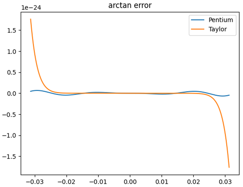
Comparison of the Pentium's double-precision arctan polynomial to the Taylor series.

Comparison of the Pentium's double-precision arctan polynomial to the Taylor series.

Trig functions

Sine and cosine each have two polynomial implementations, one with 4 terms in the ROM and one with 6 terms in the ROM. (Note that coefficients of 1 are not stored in the ROM.) The constant table also holds 16 constants such as sin(36/64) and cos(18/64) that are used for argument range reduction.10 The Pentium computes tangent by dividing the sine by the cosine. I'm not showing a graph because the Pentium's error came out worse than the Taylor series, so either I have an error in a coefficient or I'm doing something wrong.

Exponential

The Pentium has an instruction to compute a power of two.11 There are two sets of polynomial coefficients for exponential, one with 6 terms in the ROM and one with 11 terms in the ROM. Curiously, the polynomials in the ROM compute ex, not 2x. Thus, the Pentium must scale the argument by ln(2), a constant that is in the ROM. The error graph below shows the advantage of the Pentium's polynomial over the Taylor series polynomial.
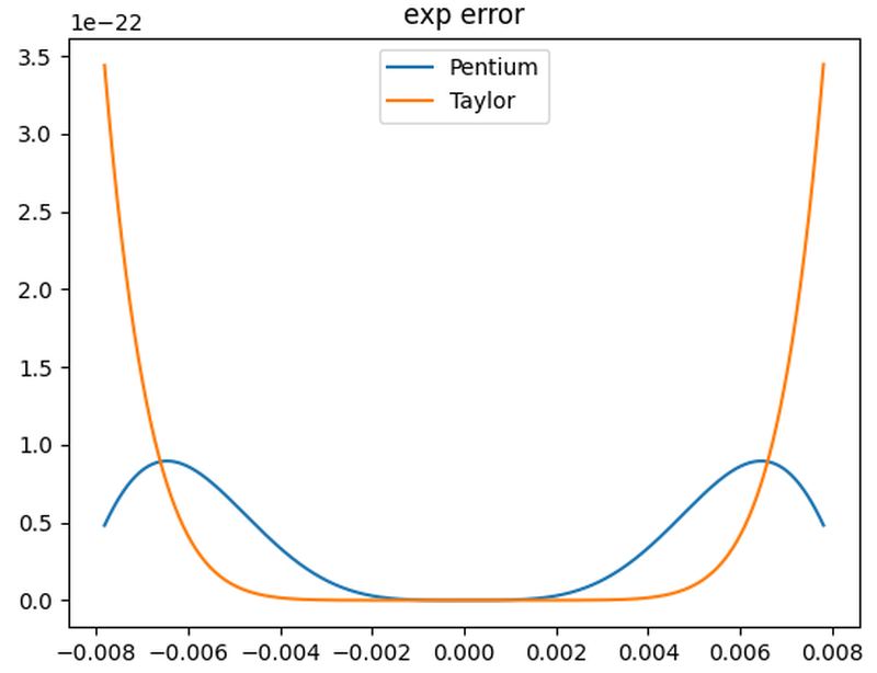
The Pentium's 6-term exponential polynomial, compared with the Taylor series.

The Pentium's 6-term exponential polynomial, compared with the Taylor series.

The polynomial handles the narrow argument range [-1/128, 1/128]. Observe that when computing a power of 2 in binary, exponentiating the integer part of the argument is trivial, since it becomes the result's exponent. Thus, the function only needs to handle the range [1, 2]. For range reduction, the constant ROM holds 64 values of the form 2n/128-1. To reduce the range from [1, 2] to [-1/128, 1/128], the closest n/128 is subtracted from the argument and then the result is multiplied by the corresponding constant in the ROM. The constants are spaced irregularly, presumably for accuracy; some are in steps of 4/128 and others are in steps of 2/128.

Logarithm

The Pentium can compute base-2 logarithms.12 The coefficients define polynomials for the hyperbolic arctan, which is closely related to log. See the comments for details. The ROM also has 64 constants for range reduction: log2(1+n/64) for odd n from 1 to 63. The unusual feature of these constants is that each constant is split into two pieces to increase the bits of accuracy: the top part has 40 bits of accuracy and the bottom part has 67 bits of accuracy, providing a 107-bit constant in total. The extra bits are required because logarithms are hard to compute accurately.

Other constants

The x87 floating-point instruction set provides direct access to a handful of constants—0, 1, pi, log2(10), log2(e), log10(2), and loge(2)—so these constants are stored in the ROM. (These logs are useful for changing the base for logs and exponentials.) The ROM holds other constants for internal use by the floating-point unit such as -1, 2, 7/8, 9/8, pi/2, pi/4, and 2log2(e). The ROM also holds bitmasks for extracting part of a word, for instance accessing 4-bit BCD digits in a word. Although I can interpret most of the values, there are a few mysteries such as a mask with the inscrutable value 0x3e8287c. The ROM has 34 unused entries at the end; these entries hold words that include the descriptive hex value 0xbad or perhaps 0xbadfc for "bad float constant".

How I examined the ROM

To analyze the Pentium, I removed the metal and oxide layers with various chemicals (sulfuric acid, phosphoric acid, Whink). (I later discovered that simply sanding the die works surprisingly well.) Next, I took many photos of the ROM with a microscope. The feature size of this Pentium is 800 nm, just slightly larger than visible light (380-700 nm). Thus, the die can be examined under an optical microscope, but it is getting close to the limits. To determine the ROM contents, I tediously went through the ROM images, examining each of the 26144 bits and marking each transistor. After figuring out the ROM format, I wrote programs to combine simple functions in many different combinations to determine the mathematical expression such as arctan(19/32) or log2(10). Because the polynomial constants are optimized and my ROM data has bit errors, my program needed checks for inexact matches, both numerically and bitwise. Finally, I had to determine how the constants would be used in algorithms.

Conclusions

By examining the Pentium's floating-point ROM under a microscope, it is possible to extract the 304 constants stored in the ROM. I was able to determine the meaning of most of these constants and deduce some of the floating-point algorithms used by the Pentium. These constants illustrate how polynomials can efficiently compute transcendental functions. Although Taylor series polynomials are well known, they are surprisingly inaccurate and should be avoided. Minor changes to the coefficients through the Remez algorithm, however, yield much better polynomials.

In a previous article, I examined the floating-point constants stored in the 8087 coprocessor. The Pentium has 304 constants in the Pentium, compared to just 42 in the 8087, supporting more efficient algorithms. Moreover, the 8087 was an external floating-point unit, while the Pentium's floating-point unit is part of the processor. The changes between the 8087 (1980, 65,000 transistors) and the Pentium (1993, 3.1 million transistors) are due to the exponential improvements in transistor count, as described by Moore's Law.

I plan to write more about the Pentium so follow me on Bluesky (@righto.com) or RSS for updates. (I'm no longer on Twitter.) I've also written about the Pentium division bug and the Pentium Navajo rug. Thanks to CuriousMarc for microscope help. Thanks to lifthrasiir and Alexia for identifying some constants.

Appendix: The constant ROM

The table below lists the 304 constants in the Pentium's floating-point ROM. The first four columns show the values stored in the ROM: the exponent, the sign bit, the flag bit, and the significand. To avoid negative exponents, exponents are stored with the constant 0x0ffff added. For example, the value 0x0fffe represents an exponent of -1, while 0x10000 represents an exponent of 1. The constant's approximate decimal value is in the "value" column.

Special-purpose values are colored. Specifically, "normal" numbers are in black. Constants with an exponent of all 0's are in blue, constants with an exponent of all 1's are in red, constants with an unusually large or small exponent are in green; these appear to be bitmasks rather than numbers. Unused entries are in gray. Inexact constants (due to Remez optimization) are represented with the approximation symbol "≈".

This information is from my reverse engineering, so there will be a few errors.

expSFsignificandvaluemeaning
0 00000 0 0 07878787878787878 BCD mask by 4's
1 00000 0 0 007f807f807f807f8 BCD mask by 8's
2 00000 0 0 00007fff80007fff8 BCD mask by 16's
3 00000 0 0 000000007fffffff8 BCD mask by 32's
4 00000 0 0 78000000000000000 4-bit mask
5 00000 0 0 18000000000000000 2-bit mask
6 00000 0 0 27000000000000000 ?
7 00000 0 0 363c0000000000000 ?
8 00000 0 0 3e8287c0000000000 ?
9 00000 0 0 470de4df820000000 213×1016
10 00000 0 0 5c3bd5191b525a249 2123/1017
11 00000 0 0 00000000000000007 3-bit mask
12 1ffff 1 1 7ffffffffffffffff all 1's
13 00000 0 0 0000007ffffffffff mask for 32-bit float
14 00000 0 0 00000000000003fff mask for 64-bit float
15 00000 0 0 00000000000000000 all 0's
16 0ffff 0 0 40000000000000000  1 1
17 10000 0 0 6a4d3c25e68dc57f2  3.3219280949 log2(10)
18 0ffff 0 0 5c551d94ae0bf85de  1.4426950409 log2(e)
19 10000 0 0 6487ed5110b4611a6  3.1415926536 pi
20 0ffff 0 0 6487ed5110b4611a6  1.5707963268 pi/2
21 0fffe 0 0 6487ed5110b4611a6  0.7853981634 pi/4
22 0fffd 0 0 4d104d427de7fbcc5  0.3010299957 log10(2)
23 0fffe 0 0 58b90bfbe8e7bcd5f  0.6931471806 ln(2)
24 1ffff 0 0 40000000000000000 +infinity
25 0bfc0 0 0 40000000000000000 1/4 of smallest 80-bit denormal?
26 1ffff 1 0 60000000000000000 NaN (not a number)
27 0ffff 1 0 40000000000000000 -1 -1
28 10000 0 0 40000000000000000  2 2
29 00000 0 0 00000000000000001 low bit
30 00000 0 0 00000000000000000 all 0's
31 00001 0 0 00000000000000000 single exponent bit
32 0fffe 0 0 58b90bfbe8e7bcd5e  0.6931471806 ln(2)
33 0fffe 0 0 40000000000000000  0.5 1/2! (exp Taylor series)
34 0fffc 0 0 5555555555555584f  0.1666666667 ≈1/3!
35 0fffa 0 0 555555555397fffd4  0.0416666667 ≈1/4!
36 0fff8 0 0 444444444250ced0c  0.0083333333 ≈1/5!
37 0fff5 0 0 5b05c3dd3901cea50  0.0013888934 ≈1/6!
38 0fff2 0 0 6806988938f4f2318  0.0001984134 ≈1/7!
39 0fffe 0 0 40000000000000000  0.5 1/2! (exp Taylor series)
40 0fffc 0 0 5555555555555558e  0.1666666667 ≈1/3!
41 0fffa 0 0 5555555555555558b  0.0416666667 ≈1/4!
42 0fff8 0 0 444444444443db621  0.0083333333 ≈1/5!
43 0fff5 0 0 5b05b05b05afd42f4  0.0013888889 ≈1/6!
44 0fff2 0 0 68068068163b44194  0.0001984127 ≈1/7!
45 0ffef 0 0 6806806815d1b6d8a  0.0000248016 ≈1/8!
46 0ffec 0 0 5c778d8e0384c73ab  2.755731e-06 ≈1/9!
47 0ffe9 0 0 49f93e0ef41d6086b  2.755731e-07 ≈1/10!
48 0ffe5 0 0 6ba8b65b40f9c0ce8  2.506632e-08 ≈1/11!
49 0ffe2 0 0 47c5b695d0d1289a8  2.088849e-09 ≈1/12!
50 0fffd 0 0 6dfb23c651a2ef221  0.4296133384 266/128-1
51 0fffd 0 0 75feb564267c8bf6f  0.4609177942 270/128-1
52 0fffd 0 0 7e2f336cf4e62105d  0.4929077283 274/128-1
53 0fffe 0 0 4346ccda249764072  0.5255981507 278/128-1
54 0fffe 0 0 478d74c8abb9b15cc  0.5590044002 282/128-1
55 0fffe 0 0 4bec14fef2727c5cf  0.5931421513 286/128-1
56 0fffe 0 0 506333daef2b2594d  0.6280274219 290/128-1
57 0fffe 0 0 54f35aabcfedfa1f6  0.6636765803 294/128-1
58 0fffe 0 0 599d15c278afd7b60  0.7001063537 298/128-1
59 0fffe 0 0 5e60f4825e0e9123e  0.7373338353 2102/128-1
60 0fffe 0 0 633f8972be8a5a511  0.7753764925 2106/128-1
61 0fffe 0 0 68396a503c4bdc688  0.8142521755 2110/128-1
62 0fffe 0 0 6d4f301ed9942b846  0.8539791251 2114/128-1
63 0fffe 0 0 7281773c59ffb139f  0.8945759816 2118/128-1
64 0fffe 0 0 77d0df730ad13bb90  0.9360617935 2122/128-1
65 0fffe 0 0 7d3e0c0cf486c1748  0.9784560264 2126/128-1
66 0fffc 0 0 642e1f899b0626a74  0.1956643920 233/128-1
67 0fffc 0 0 6ad8abf253fe1928c  0.2086843236 235/128-1
68 0fffc 0 0 7195cda0bb0cb0b54  0.2218460330 237/128-1
69 0fffc 0 0 7865b862751c90800  0.2351510639 239/128-1
70 0fffc 0 0 7f48a09590037417f  0.2486009772 241/128-1
71 0fffd 0 0 431f5d950a896dc70  0.2621973504 243/128-1
72 0fffd 0 0 46a41ed1d00577251  0.2759417784 245/128-1
73 0fffd 0 0 4a32af0d7d3de672e  0.2898358734 247/128-1
74 0fffd 0 0 4dcb299fddd0d63b3  0.3038812652 249/128-1
75 0fffd 0 0 516daa2cf6641c113  0.3180796013 251/128-1
76 0fffd 0 0 551a4ca5d920ec52f  0.3324325471 253/128-1
77 0fffd 0 0 58d12d497c7fd252c  0.3469417862 255/128-1
78 0fffd 0 0 5c9268a5946b701c5  0.3616090206 257/128-1
79 0fffd 0 0 605e1b976dc08b077  0.3764359708 259/128-1
80 0fffd 0 0 6434634ccc31fc770  0.3914243758 261/128-1
81 0fffd 0 0 68155d44ca973081c  0.4065759938 263/128-1
82 0fffd 1 0 4cee3bed56eedb76c -0.3005101637 2-66/128-1
83 0fffd 1 0 50c4875296f5bc8b2 -0.3154987885 2-70/128-1
84 0fffd 1 0 5485c64a56c12cc8a -0.3301662380 2-74/128-1
85 0fffd 1 0 58326c4b169aca966 -0.3445193942 2-78/128-1
86 0fffd 1 0 5bcaea51f6197f61f -0.3585649920 2-82/128-1
87 0fffd 1 0 5f4faef0468eb03de -0.3723096215 2-86/128-1
88 0fffd 1 0 62c12658d30048af2 -0.3857597319 2-90/128-1
89 0fffd 1 0 661fba6cdf48059b2 -0.3989216343 2-94/128-1
90 0fffd 1 0 696bd2c8dfe7a5ffb -0.4118015042 2-98/128-1
91 0fffd 1 0 6ca5d4d0ec1916d43 -0.4244053850 2-102/128-1
92 0fffd 1 0 6fce23bceb994e239 -0.4367391907 2-106/128-1
93 0fffd 1 0 72e520a481a4561a5 -0.4488087083 2-110/128-1
94 0fffd 1 0 75eb2a8ab6910265f -0.4606196011 2-114/128-1
95 0fffd 1 0 78e09e696172efefc -0.4721774108 2-118/128-1
96 0fffd 1 0 7bc5d73c5321bfb9e -0.4834875605 2-122/128-1
97 0fffd 1 0 7e9b2e0c43fcf88c8 -0.4945553570 2-126/128-1
98 0fffc 1 0 53c94402c0c863f24 -0.1636449102 2-33/128-1
99 0fffc 1 0 58661eccf4ca790d2 -0.1726541162 2-35/128-1
100 0fffc 1 0 5cf6413b5d2cca73f -0.1815662751 2-37/128-1
101 0fffc 1 0 6179ce61cdcdce7db -0.1903824324 2-39/128-1
102 0fffc 1 0 65f0e8f35f84645cf -0.1991036222 2-41/128-1
103 0fffc 1 0 6a5bb3437adf1164b -0.2077308674 2-43/128-1
104 0fffc 1 0 6eba4f46e003a775a -0.2162651800 2-45/128-1
105 0fffc 1 0 730cde94abb7410d5 -0.2247075612 2-47/128-1
106 0fffc 1 0 775382675996699ad -0.2330590011 2-49/128-1
107 0fffc 1 0 7b8e5b9dc385331ad -0.2413204794 2-51/128-1
108 0fffc 1 0 7fbd8abc1e5ee49f2 -0.2494929652 2-53/128-1
109 0fffd 1 0 41f097f679f66c1db -0.2575774171 2-55/128-1
110 0fffd 1 0 43fcb5810d1604f37 -0.2655747833 2-57/128-1
111 0fffd 1 0 46032dbad3f462152 -0.2734860021 2-59/128-1
112 0fffd 1 0 48041035735be183c -0.2813120013 2-61/128-1
113 0fffd 1 0 49ff6c57a12a08945 -0.2890536989 2-63/128-1
114 0fffd 1 0 555555555555535f0 -0.3333333333 ≈-1/3 (arctan Taylor series)
115 0fffc 0 0 6666666664208b016  0.2 ≈ 1/5
116 0fffc 1 0 492491e0653ac37b8 -0.1428571307 ≈-1/7
117 0fffb 0 0 71b83f4133889b2f0  0.1110544094 ≈ 1/9
118 0fffd 1 0 55555555555555543 -0.3333333333 ≈-1/3 (arctan Taylor series)
119 0fffc 0 0 66666666666616b73  0.2 ≈ 1/5
120 0fffc 1 0 4924924920fca4493 -0.1428571429 ≈-1/7
121 0fffb 0 0 71c71c4be6f662c91  0.1111111089 ≈ 1/9
122 0fffb 1 0 5d16e0bde0b12eee8 -0.0909075848 ≈-1/11
123 0fffb 0 0 4e403be3e3c725aa0  0.0764169081 ≈ 1/13
124 00000 0 0 40000000000000000 single bit mask
125 0fff9 0 0 7ff556eea5d892a14  0.0312398334 arctan(1/32)
126 0fffa 0 0 7fd56edcb3f7a71b6  0.0624188100 arctan(2/32)
127 0fffb 0 0 5fb860980bc43a305  0.0934767812 arctan(3/32)
128 0fffb 0 0 7f56ea6ab0bdb7196  0.1243549945 arctan(4/32)
129 0fffc 0 0 4f5bbba31989b161a  0.1549967419 arctan(5/32)
130 0fffc 0 0 5ee5ed2f396c089a4  0.1853479500 arctan(6/32)
131 0fffc 0 0 6e435d4a498288118  0.2153576997 arctan(7/32)
132 0fffc 0 0 7d6dd7e4b203758ab  0.2449786631 arctan(8/32)
133 0fffd 0 0 462fd68c2fc5e0986  0.2741674511 arctan(9/32)
134 0fffd 0 0 4d89dcdc1faf2f34e  0.3028848684 arctan(10/32)
135 0fffd 0 0 54c2b6654735276d5  0.3310960767 arctan(11/32)
136 0fffd 0 0 5bd86507937bc239c  0.3587706703 arctan(12/32)
137 0fffd 0 0 62c934e5286c95b6d  0.3858826694 arctan(13/32)
138 0fffd 0 0 6993bb0f308ff2db2  0.4124104416 arctan(14/32)
139 0fffd 0 0 7036d3253b27be33e  0.4383365599 arctan(15/32)
140 0fffd 0 0 76b19c1586ed3da2b  0.4636476090 arctan(16/32)
141 0fffd 0 0 7d03742d50505f2e3  0.4883339511 arctan(17/32)
142 0fffe 0 0 4195fa536cc33f152  0.5123894603 arctan(18/32)
143 0fffe 0 0 4495766fef4aa3da8  0.5358112380 arctan(19/32)
144 0fffe 0 0 47802eaf7bfacfcdb  0.5585993153 arctan(20/32)
145 0fffe 0 0 4a563964c238c37b1  0.5807563536 arctan(21/32)
146 0fffe 0 0 4d17c07338deed102  0.6022873461 arctan(22/32)
147 0fffe 0 0 4fc4fee27a5bd0f68  0.6231993299 arctan(23/32)
148 0fffe 0 0 525e3e8c9a7b84921  0.6435011088 arctan(24/32)
149 0fffe 0 0 54e3d5ee24187ae45  0.6632029927 arctan(25/32)
150 0fffe 0 0 5756261c5a6c60401  0.6823165549 arctan(26/32)
151 0fffe 0 0 59b598e48f821b48b  0.7008544079 arctan(27/32)
152 0fffe 0 0 5c029f15e118cf39e  0.7188299996 arctan(28/32)
153 0fffe 0 0 5e3daef574c579407  0.7362574290 arctan(29/32)
154 0fffe 0 0 606742dc562933204  0.7531512810 arctan(30/32)
155 0fffe 0 0 627fd7fd5fc7deaa4  0.7695264804 arctan(31/32)
156 0fffe 0 0 6487ed5110b4611a6  0.7853981634 arctan(32/32)
157 0fffc 1 0 55555555555555555 -0.1666666667 ≈-1/3! (sin Taylor series)
158 0fff8 0 0 44444444444443e35  0.0083333333 ≈ 1/5!
159 0fff2 1 0 6806806806773c774 -0.0001984127 ≈-1/7!
160 0ffec 0 0 5c778e94f50956d70  2.755732e-06 ≈ 1/9!
161 0ffe5 1 0 6b991122efa0532f0 -2.505209e-08 ≈-1/11!
162 0ffde 0 0 58303f02614d5e4d8  1.604139e-10 ≈ 1/13!
163 0fffd 1 0 7fffffffffffffffe -0.5 ≈-1/2! (cos Taylor series)
164 0fffa 0 0 55555555555554277  0.0416666667 ≈ 1/4!
165 0fff5 1 0 5b05b05b05a18a1ba -0.0013888889 ≈-1/6!
166 0ffef 0 0 680680675b559f2cf  0.0000248016 ≈ 1/8!
167 0ffe9 1 0 49f93af61f5349300 -2.755730e-07 ≈-1/10!
168 0ffe2 0 0 47a4f2483514c1af8  2.085124e-09 ≈ 1/12!
169 0fffc 1 0 55555555555555445 -0.1666666667 ≈-1/3! (sin Taylor series)
170 0fff8 0 0 44444444443a3fdb6  0.0083333333 ≈ 1/5!
171 0fff2 1 0 68068060b2044e9ae -0.0001984127 ≈-1/7!
172 0ffec 0 0 5d75716e60f321240  2.785288e-06 ≈ 1/9!
173 0fffd 1 0 7fffffffffffffa28 -0.5 ≈-1/2! (cos Taylor series)
174 0fffa 0 0 555555555539cfae6  0.0416666667 ≈ 1/4!
175 0fff5 1 0 5b05b050f31b2e713 -0.0013888889 ≈-1/6!
176 0ffef 0 0 6803988d56e3bff10  0.0000247989 ≈ 1/8!
177 0fffe 0 0 44434312da70edd92  0.5333026735 sin(36/64)
178 0fffe 0 0 513ace073ce1aac13  0.6346070800 sin(44/64)
179 0fffe 0 0 5cedda037a95df6ee  0.7260086553 sin(52/64)
180 0fffe 0 0 672daa6ef3992b586  0.8060811083 sin(60/64)
181 0fffd 0 0 470df5931ae1d9460  0.2775567516 sin(18/64)
182 0fffd 0 0 5646f27e8bd65cbe4  0.3370200690 sin(22/64)
183 0fffd 0 0 6529afa7d51b12963  0.3951673302 sin(26/64)
184 0fffd 0 0 73a74b8f52947b682  0.4517714715 sin(30/64)
185 0fffe 0 0 6c4741058a93188ef  0.8459244992 cos(36/64)
186 0fffe 0 0 62ec41e9772401864  0.7728350058 cos(44/64)
187 0fffe 0 0 5806149bd58f7d46d  0.6876855622 cos(52/64)
188 0fffe 0 0 4bc044c9908390c72  0.5918050751 cos(60/64)
189 0fffe 0 0 7af8853ddbbe9ffd0  0.9607092430 cos(18/64)
190 0fffe 0 0 7882fd26b35b03d34  0.9414974631 cos(22/64)
191 0fffe 0 0 7594fc1cf900fe89e  0.9186091558 cos(26/64)
192 0fffe 0 0 72316fe3386a10d5a  0.8921336994 cos(30/64)
193 0ffff 0 0 48000000000000000  1.125 9/8
194 0fffe 0 0 70000000000000000  0.875 7/8
195 0ffff 0 0 5c551d94ae0bf85de  1.4426950409 log2(e)
196 10000 0 0 5c551d94ae0bf85de  2.8853900818 2log2(e)
197 0fffb 0 0 7b1c2770e81287c11  0.1202245867 ≈1/(41⋅3⋅ln(2)) (atanh series for log)
198 0fff9 0 0 49ddb14064a5d30bd  0.0180336880 ≈1/(42⋅5⋅ln(2))
199 0fff6 0 0 698879b87934f12e0  0.0032206148 ≈1/(43⋅7⋅ln(2))
200 0fffa 0 0 51ff4ffeb20ed1749  0.0400377512 ≈(ln(2)/2)2/3 (atanh series for log)
201 0fff6 0 0 5e8cd07eb1827434a  0.0028854387 ≈(ln(2)/2)4/5
202 0fff3 0 0 40e54061b26dd6dc2  0.0002475567 ≈(ln(2)/2)6/7
203 0ffef 0 0 61008a69627c92fb9  0.0000231271 ≈(ln(2)/2)8/9
204 0ffec 0 0 4c41e6ced287a2468  2.272648e-06 ≈(ln(2)/2)10/11
205 0ffe8 0 0 7dadd4ea3c3fee620  2.340954e-07 ≈(ln(2)/2)12/13
206 0fff9 0 0 5b9e5a170b8000000  0.0223678130 log2(1+1/64) top bits
207 0fffb 0 0 43ace37e8a8000000  0.0660892054 log2(1+3/64) top bits
208 0fffb 0 0 6f210902b68000000  0.1085244568 log2(1+5/64) top bits
209 0fffc 0 0 4caba789e28000000  0.1497471195 log2(1+7/64) top bits
210 0fffc 0 0 6130af40bc0000000  0.1898245589 log2(1+9/64) top bits
211 0fffc 0 0 7527b930c98000000  0.2288186905 log2(1+11/64) top bits
212 0fffd 0 0 444c1f6b4c0000000  0.2667865407 log2(1+13/64) top bits
213 0fffd 0 0 4dc4933a930000000  0.3037807482 log2(1+15/64) top bits
214 0fffd 0 0 570068e7ef8000000  0.3398500029 log2(1+17/64) top bits
215 0fffd 0 0 6002958c588000000  0.3750394313 log2(1+19/64) top bits
216 0fffd 0 0 68cdd829fd8000000  0.4093909361 log2(1+21/64) top bits
217 0fffd 0 0 7164beb4a58000000  0.4429434958 log2(1+23/64) top bits
218 0fffd 0 0 79c9aa879d8000000  0.4757334310 log2(1+25/64) top bits
219 0fffe 0 0 40ff6a2e5e8000000  0.5077946402 log2(1+27/64) top bits
220 0fffe 0 0 450327ea878000000  0.5391588111 log2(1+29/64) top bits
221 0fffe 0 0 48f107509c8000000  0.5698556083 log2(1+31/64) top bits
222 0fffe 0 0 4cc9f1aad28000000  0.5999128422 log2(1+33/64) top bits
223 0fffe 0 0 508ec1fa618000000  0.6293566201 log2(1+35/64) top bits
224 0fffe 0 0 5440461c228000000  0.6582114828 log2(1+37/64) top bits
225 0fffe 0 0 57df3fd0780000000  0.6865005272 log2(1+39/64) top bits
226 0fffe 0 0 5b6c65a9d88000000  0.7142455177 log2(1+41/64) top bits
227 0fffe 0 0 5ee863e4d40000000  0.7414669864 log2(1+43/64) top bits
228 0fffe 0 0 6253dd2c1b8000000  0.7681843248 log2(1+45/64) top bits
229 0fffe 0 0 65af6b4ab30000000  0.7944158664 log2(1+47/64) top bits
230 0fffe 0 0 68fb9fce388000000  0.8201789624 log2(1+49/64) top bits
231 0fffe 0 0 6c39049af30000000  0.8454900509 log2(1+51/64) top bits
232 0fffe 0 0 6f681c731a0000000  0.8703647196 log2(1+53/64) top bits
233 0fffe 0 0 72896372a50000000  0.8948177633 log2(1+55/64) top bits
234 0fffe 0 0 759d4f80cb8000000  0.9188632373 log2(1+57/64) top bits
235 0fffe 0 0 78a450b8380000000  0.9425145053 log2(1+59/64) top bits
236 0fffe 0 0 7b9ed1c6ce8000000  0.9657842847 log2(1+61/64) top bits
237 0fffe 0 0 7e8d3845df0000000  0.9886846868 log2(1+63/64) top bits
238 0ffd0 1 0 6eb3ac8ec0ef73f7b -1.229037e-14 log2(1+1/64) bottom bits
239 0ffcd 1 0 654c308b454666de9 -1.405787e-15 log2(1+3/64) bottom bits
240 0ffd2 0 0 5dd31d962d3728cbd  4.166652e-14 log2(1+5/64) bottom bits
241 0ffd3 0 0 70d0fa8f9603ad3a6  1.002010e-13 log2(1+7/64) bottom bits
242 0ffd1 0 0 765fba4491dcec753  2.628429e-14 log2(1+9/64) bottom bits
243 0ffd2 1 0 690370b4a9afdc5fb -4.663533e-14 log2(1+11/64) bottom bits
244 0ffd4 0 0 5bae584b82d3cad27  1.628582e-13 log2(1+13/64) bottom bits
245 0ffd4 0 0 6f66cc899b64303f7  1.978889e-13 log2(1+15/64) bottom bits
246 0ffd4 1 0 4bc302ffa76fafcba -1.345799e-13 log2(1+17/64) bottom bits
247 0ffd2 1 0 7579aa293ec16410a -5.216949e-14 log2(1+19/64) bottom bits
248 0ffcf 0 0 509d7c40d7979ec5b  4.475041e-15 log2(1+21/64) bottom bits
249 0ffd3 1 0 4a981811ab5110ccf -6.625289e-14 log2(1+23/64) bottom bits
250 0ffd4 1 0 596f9d730f685c776 -1.588702e-13 log2(1+25/64) bottom bits
251 0ffd4 1 0 680cc6bcb9bfa9853 -1.848298e-13 log2(1+27/64) bottom bits
252 0ffd4 0 0 5439e15a52a31604a  1.496156e-13 log2(1+29/64) bottom bits
253 0ffd4 0 0 7c8080ecc61a98814  2.211599e-13 log2(1+31/64) bottom bits
254 0ffd3 1 0 6b26f28dbf40b7bc0 -9.517022e-14 log2(1+33/64) bottom bits
255 0ffd5 0 0 554b383b0e8a55627  3.030245e-13 log2(1+35/64) bottom bits
256 0ffd5 0 0 47c6ef4a49bc59135  2.550034e-13 log2(1+37/64) bottom bits
257 0ffd5 0 0 4d75c658d602e66b0  2.751934e-13 log2(1+39/64) bottom bits
258 0ffd4 1 0 6b626820f81ca95da -1.907530e-13 log2(1+41/64) bottom bits
259 0ffd3 0 0 5c833d56efe4338fe  8.216774e-14 log2(1+43/64) bottom bits
260 0ffd5 0 0 7c5a0375163ec8d56  4.417857e-13 log2(1+45/64) bottom bits
261 0ffd5 1 0 5050809db75675c90 -2.853343e-13 log2(1+47/64) bottom bits
262 0ffd4 1 0 7e12f8672e55de96c -2.239526e-13 log2(1+49/64) bottom bits
263 0ffd5 0 0 435ebd376a70d849b  2.393466e-13 log2(1+51/64) bottom bits
264 0ffd2 1 0 6492ba487dfb264b3 -4.466345e-14 log2(1+53/64) bottom bits
265 0ffd5 1 0 674e5008e379faa7c -3.670163e-13 log2(1+55/64) bottom bits
266 0ffd5 0 0 5077f1f5f0cc82aab  2.858817e-13 log2(1+57/64) bottom bits
267 0ffd2 0 0 5007eeaa99f8ef14d  3.554090e-14 log2(1+59/64) bottom bits
268 0ffd5 0 0 4a83eb6e0f93f7a64  2.647316e-13 log2(1+61/64) bottom bits
269 0ffd3 0 0 466c525173dae9cf5  6.254831e-14 log2(1+63/64) bottom bits
270 0badf 0 1 40badfc0badfc0bad unused
271 0badf 0 1 40badfc0badfc0bad unused
272 0badf 0 1 40badfc0badfc0bad unused
273 0badf 0 1 40badfc0badfc0bad unused
274 0badf 0 1 40badfc0badfc0bad unused
275 0badf 0 1 40badfc0badfc0bad unused
276 0badf 0 1 40badfc0badfc0bad unused
277 0badf 0 1 40badfc0badfc0bad unused
278 0badf 0 1 40badfc0badfc0bad unused
279 0badf 0 1 40badfc0badfc0bad unused
280 0badf 0 1 40badfc0badfc0bad unused
281 0badf 0 1 40badfc0badfc0bad unused
282 0badf 0 1 40badfc0badfc0bad unused
283 0badf 0 1 40badfc0badfc0bad unused
284 0badf 0 1 40badfc0badfc0bad unused
285 0badf 0 1 40badfc0badfc0bad unused
286 0badf 0 1 40badfc0badfc0bad unused
287 0badf 0 1 40badfc0badfc0bad unused
288 0badf 0 1 40badfc0badfc0bad unused
289 0badf 0 1 40badfc0badfc0bad unused
290 0badf 0 1 40badfc0badfc0bad unused
291 0badf 0 1 40badfc0badfc0bad unused
292 0badf 0 1 40badfc0badfc0bad unused
293 0badf 0 1 40badfc0badfc0bad unused
294 0badf 0 1 40badfc0badfc0bad unused
295 0badf 0 1 40badfc0badfc0bad unused
296 0badf 0 1 40badfc0badfc0bad unused
297 0badf 0 1 40badfc0badfc0bad unused
298 0badf 0 1 40badfc0badfc0bad unused
299 0badf 0 1 40badfc0badfc0bad unused
300 0badf 0 1 40badfc0badfc0bad unused
301 0badf 0 1 40badfc0badfc0bad unused
302 0badf 0 1 40badfc0badfc0bad unused
303 0badf 0 1 40badfc0badfc0bad unused

Notes and references
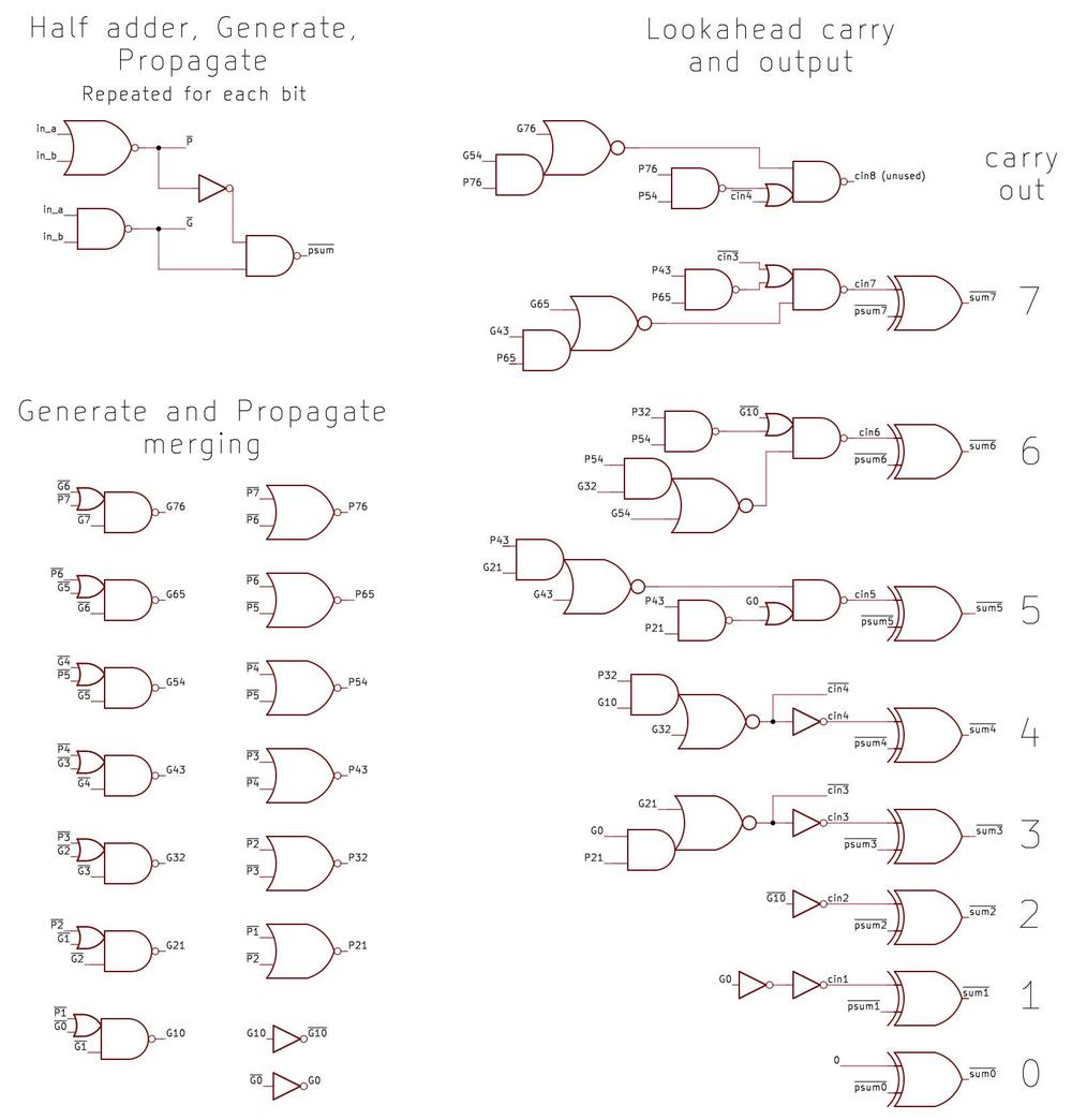
  1. In this blog post, I'm looking at the "P5" version of the original Pentium processor. It can be hard to keep all the Pentiums straight since "Pentium" became a brand name with multiple microarchitectures, lines, and products. The original Pentium (1993) was followed by the Pentium Pro (1995), Pentium II (1997), and so on.

    The original Pentium used the P5 microarchitecture, a superscalar microarchitecture that was advanced but still executed instruction in order like traditional microprocessors. The original Pentium went through several substantial revisions. The first Pentium product was the 80501 (codenamed P5), containing 3.1 million transistors. The power consumption of these chips was disappointing, so Intel improved the chip, producing the 80502, codenamed P54C. The P5 and P54C look almost the same on the die, but the P54C added circuitry for multiprocessing, boosting the transistor count to 3.3 million. The biggest change to the original Pentium was the Pentium MMX, with part number 80503 and codename P55C. The Pentium MMX added 57 vector processing instructions and had 4.5 million transistors. The floating-point unit was rearranged in the MMX, but the constants are probably the same. 

  2. I don't know what the flag bit in the ROM indicates; I'm arbitrarily calling it a flag. My wild guess is that it indicates ROM entries that should be excluded from the checksum when testing the ROM. 
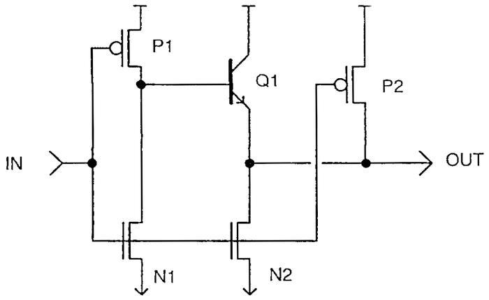
  3. Internally, the significand has one integer bit and the remainder is the fraction, so the binary point (decimal point) is after the first bit. However, this is not the only way to represent the significand. The x87 80-bit floating-point format (double extended-precision) uses the same approach. However, the 32-bit (single-precision) and 64-bit (double-precision) formats drop the first bit and use an "implied" one bit. This gives you one more bit of significand "for free" since in normal cases the first significand bit will be 1. 

  4. An unusual feature of the Pentium is that it uses bipolar NPN transistors along with CMOS circuits, a technology called BiCMOS. By adding a few extra processing steps to the regular CMOS manufacturing process, bipolar transistors could be created. The Pentium uses BiCMOS circuits extensively since they reduced signal delays by up to 35%. Intel also used BiCMOS for the Pentium Pro, Pentium II, Pentium III, and Xeon processors (but not the Pentium MMX). However, as chip voltages dropped, the benefit from bipolar transistors dropped too and BiCMOS was eventually abandoned.

    In the constant ROM, BiCMOS circuits improve the performance of the row selection circuitry. Each row select line is very long and is connected to hundreds of transistors, so the capacitive load is large. Because of the fast and powerful NPN transistor, a BiCMOS driver provides lower delay for higher loads than a regular CMOS driver.

    A typical BiCMOS inverter. From A 3.3V 0.6µm BiCMOS superscalar microprocessor.

    A typical BiCMOS inverter. From A 3.3V 0.6µm BiCMOS superscalar microprocessor.

    This BiCMOS logic is also called BiNMOS or BinMOS because the output has a bipolar transistor and an NMOS transistor. For more on BiCMOS circuits in the Pentium, see my article Standard cells: Looking at individual gates in the Pentium processor

  5. The integer processing unit of the Pentium is constructed similarly, with horizontal functional units stacked to form the datapath. Each cell in the integer unit is much wider than a floating-point cell (64 µm vs 38.5 µm). However, the integer unit is just 32 bits wide, compared to 69 (more or less) for the floating-point unit, so the floating-point unit is wider overall. 

  6. I don't like referring to the argument's range since a function's output is the range, while its input is the domain. But the term range reduction is what people use, so I'll go with it. 

  7. There's a reason why the error curve looks similar even if you reduce the range. The error from the Taylor series is approximately the next term in the Taylor series, so in this case the error is roughly -x11/11! or O(x11). This shows why range reduction is so powerful: if you reduce the range by a factor of 2, you reduce the error by the enormous factor of 211. But this also shows why the error curve keeps its shape: the curve is still x11, just with different labels on the axes. 

  8. The Pentium coefficients are probably obtained using the Remez algorithm; see Floating-Point Verification. The advantages of the Remez polynomial over the Taylor series are discussed in Better Function Approximations: Taylor vs. Remez. A description of Remez's algorithm is in Elementary Functions: Algorithms and Implementation, which has other relevant information on polynomial approximation and range reduction. For more on polynomial approximations, see Numerically Computing the Exponential Function with Polynomial Approximations and The Eight Useful Polynomial Approximations of Sinf(3),

    The Remez polynomial in the sine graph is not the Pentium polynomial; it was generated for illustration by lolremez, a useful tool. The specific polynomial is:

    9.9997938808335731e-1 ⋅ x - 1.6662438518867169e-1 ⋅ x3 + 8.3089850302282266e-3 ⋅ x5 - 1.9264997445395096e-4 ⋅ x7 + 2.1478735041839789e-6 ⋅ x9

    The graph below shows the error for this polynomial. Note that the error oscillates between an upper bound and a lower bound. This is the typical appearance of a Remez polynomial. In contrast, a Taylor series will have almost no error in the middle and shoot up at the edges. This Remez polynomial was optimized for the range [-π,π]; the error explodes outside that range. The key point is that the Remez polynomial distributes the error inside the range. This minimizes the maximum error (minimax).

    Error from a Remez-optimized polynomial for sine.

    Error from a Remez-optimized polynomial for sine.

  9. I think the arctan argument is range-reduced to the range [-1/64, 1/64]. This can be accomplished with the trig identity arctan(x) = arctan((x-c)/(1+xc)) + arctan(c). The idea is that c is selected to be the value of the form n/32 closest to x. As a result, x-c will be in the desired range and the first arctan can be computed with the polynomial. The other term, arctan(c), is obtained from the lookup table in the ROM. The FPATAN (partial arctangent) instruction takes two arguments, x and y, and returns atan(y/x); this simplifies handling planar coordinates. In this case, the trig identity becomes arcan(y/x) = arctan((y-tx)/(x+ty)) + arctan c. The division operation can trigger the FDIV bug in some cases; see Computational Aspects of the Pentium Affair

  10. The Pentium has several trig instructions: FSIN, FCOS, and FSINCOS return the sine, cosine, or both (which is almost as fast as computing either). FPTAN returns the "partial tangent" consisting of two numbers that must be divided to yield the tangent. (This was due to limitations in the original 8087 coprocessor.) The Pentium returns the tangent as the first number and the constant 1 as the second number, keeping the semantics of FPTAN while being more convenient.

    The range reduction is probably based on the trig identity sin(a+b) = sin(a)cos(b)+cos(a)sin(b). To compute sin(x), select b as the closest constant in the lookup table, n/64, and then generate a=x-b. The value a will be range-reduced, so sin(a) can be computed from the polynomial. The terms sin(b) and cos(b) are available from the lookup table. The desired value sin(x) can then be computed with multiplications and addition by using the trig identity. Cosine can be computed similarly. Note that cos(a+b) =cos(a)cos(b)-sin(a)sin(b); the terms on the right are the same as for sin(a+b), just combined differently. Thus, once the terms on the right have been computed, they can be combined to generate sine, cosine, or both. The Pentium computes the tangent by dividing the sine by the cosine. This can trigger the FDIV division bug; see Computational Aspects of the Pentium Affair.

    Also see Agner Fog's Instruction Timings; the timings for the various operations give clues as to how they are computed. For instance, FPTAN takes longer than FSINCOS because the tangent is generated by dividing the sine by the cosine. 

  11. For exponentials, the F2XM1 instruction computes 2x-1; subtracting 1 improves accuracy. Specifically, 2x is close to 1 for the common case when x is close to 0, so subtracting 1 as a separate operation causes you to lose most of the bits of accuracy due to cancellation. On the other hand, if you want 2x, explicitly adding 1 doesn't harm accuracy. This is an example of how the floating-point instructions are carefully designed to preserve accuracy. For details, see the book The 8087 Primer by the architects of the 8086 processor and the 8087 coprocessor. 

  12. The Pentium has base-two logarithm instructions FYL2X and FYL2XP1. The FYL2X instruction computes y log2(x) and the FYL2XP1 instruction computes y log2(x+1) The instructions include a multiplication because most logarithm operations will need to multiply to change the base; performing the multiply with internal precision increases the accuracy. The "plus-one" instruction improves accuracy for arguments close to 1, such as interest calculations.

    My hypothesis for range reduction is that the input argument is scaled to fall between 1 and 2. (Taking the log of the exponent part of the argument is trivial since the base-2 log of a base-2 power is simply the exponent.) The argument can then be divided by the largest constant 1+n/64 less than the argument. This will reduce the argument to the range [1, 1+1/32]. The log polynomial can be evaluated on the reduced argument. Finally, the ROM constant for log2(1+n/64) is added to counteract the division. The constant is split into two parts for greater accuracy.

    It took me a long time to figure out the log constants because they were split. The upper-part constants appeared to be pointlessly inaccurate since the bottom 27 bits are zeroed out. The lower-part constants appeared to be miniscule semi-random numbers around ±10-13. Eventually, I figured out that the trick was to combine the constants.