Showing posts with label oscilloscope. Show all posts

Restoring YC's Xerox Alto day 9: tracing a crash through software and hardware

Last week, after months of restoration, we finally got the vintage Xerox Alto computer to boot (details) and run programs. However, some programs (such as the mouse-based Draw program) crashed so we knew there must still be a hardware problem somewhere in the system. In today's session we traced through the software, microcode and hardware to track down the cause of these crashes.

For background, the Alto was a revolutionary computer designed at Xerox PARC in 1973 to investigate personal computing. It introduced the GUI, Ethernet and laser printers to the world, among other things. Y Combinator received an Alto from computer visionary Alan Kay and I'm helping restore the system, along with Marc Verdiell, Luca Severini, Ron Crane, Carl Claunch and Ed Thelen. The full collection of Alto restoration posts is here.

When the Xerox Alto encounters a problem, it drops into the Swat debugger.

When the Xerox Alto encounters a problem, it drops into the Swat debugger.

To assist with debugging, the Alto includes a debugger called Swat. If a program malfunctions, it drops into the Swat debugger, as seen above. The debugger lets you examine memory and set breakpoints. It is more advanced than I'd expect for 1973, including a feature to disassemble machine instructions from memory and view them with names from the symbol table.

In our case, the debugger showed that when we ran the MADTEST test program, the Alto had jumped to address 2, which triggered the debugger. The first 8 memory locations in the Xerox Alto contain TRAP instructions to catch erroneous jumps to a zero address (or near-zero address) which can happen if a subroutine return address is clobbered. By examining the stack frames, I determined which subroutine had been called when the system crashed. The problem occurred when the program was jumping to microcode that had been loaded into microcode RAM, Since this is an unusual operation, it would explain why most programs ran successfully and only a few crashed.

Microcode

Microcode is a low-level feature of most processors, but I should explain what it means for a program to jump to microcode, since this is a strange feature of the Alto. Computers execute machine code, the simple, low-level instructions that the CPU can understand; on modern computers this may be the x86 instruction set, while the Alto used the Data General Nova instruction set. Most processors, however, don't run machine instructions directly, but have a microcode layer that is invisible to the programmer. While the processor appears to be running machine instructions, it internally executes microcode, a simpler, low-level instruction set that is a better match for the hardware. Each machine instruction may turn into many micro-instructions.

The Xerox Alto uses microcode much more extensively than most computers, with microcode performing tasks such as device control that most computers do in hardware, resulting in a cheaper and more flexible system. (As Alan Kay wrote, "Hardware is just software crystallized early.") On the Alto, programmers have access to the microcode—a user program can load new microcode into special control RAM. This microcode can implement new machine instructions, optimize particular operations (analogous to GPU programming), or obtain low-level control over the system.

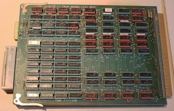
The Xerox Alto's CRAM board (Control RAM) stores 1024 microcode instructions. The 32 memory chips in the lower left provide the 1024x32 storage.

The Xerox Alto's CRAM board (Control RAM) stores 1024 microcode instructions. The 32 memory chips in the lower left provide the 1024x32 storage. Foreshadowing: the connector at the lower left connects the CRAM board to the microcode control board.

Our Alto has 1024 words of microcode in ROM (for the standard microcode) and 1024 words in RAM (for software-controlled microcode). The photo above shows the CRAM (control RAM) board that holds the user-modifiable microcode. This board illustrates the incredible improvements in memory density since 1973—this board required 32 memory chips to hold the 1024 32-bit words (4 Kbytes) of microcode.

The Alto's microcode uses a 1K (10-bit) address space. Since Altos can support up to 2K of microcode in ROM and 3K in RAM, bank switching is used to switch between different 1K memory banks. Bank switching is triggered by a special micro-instruction called SWMODE (switch mode).

Getting back to our crash, the MADTEST test program loads special test microcode into the control RAM. Then it executes the JMPRAM machine instruction to switch execution from machine instructions to the microcode in RAM. The microcode that implements JMPRAM performs a SWMODE to switch execution to the RAM microcode bank and the microcode in RAM will execute. When the microcode is done, it is supposed to return execution to the machine code emulator, and execution of the user-level program (MADTEST) will continue. But somehow execution ended up at address 2, causing the program to crash.

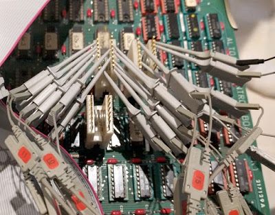
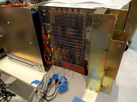
To track down a problem with the Xerox Alto's bank switching circuit, we attached many probes to the CPU control board.

To track down a problem with the Xerox Alto's bank switching circuit, we attached many probes to the CPU control board.

We used a logic analyzer to record every micro-instruction and memory access, so we could determine exactly what went wrong. After a few tries, we captured a trace showing what the Alto was executing until it crashed. Over the past week, I've been using the Living Computer Museum's ContrAlto simulator of the Xerox Alto to understand how the Alto's software and microcode work. With this background, I could interpret the logic analyzer output and map it to the MADTEST code and the microcode. Everything proceeded fine until the JMPRAM instruction was executed. Instead of switching to the microcode in RAM, it was still running microcode from the ROM. Since the micro-address was intended for the RAM code, the processor was running essentially random microcode. Through pure luck, this microcode routine completed and returned control to the regular machine code emulator rather than hanging the system. Unfortunately this code didn't load the return address register, resulting in a jump to address 2 and the Swat crash we saw.

To summarize, everything was working fine except instead of switching to the microcode RAM bank, execution stayed in the microcode ROM bank. This was pretty clearly a hardware problem, so we started looking at the bank switch circuit, which consists of multiple integrated circuits.

The bank switch hardware

The Alto was built at the dawn of the microprocessor age, so instead of using a microprocessor chip, it used three boards of TTL chips for the CPU. The control board interprets the microcode, including performing bank switching, so that's where we started our investigation.

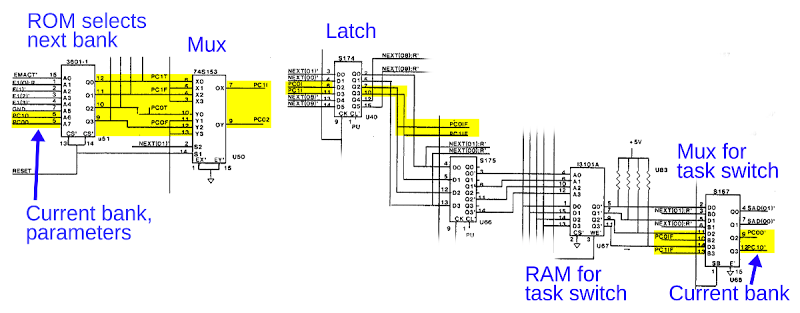
Bank switching in the Alto happens when the SWMODE micro-instruction is executed. The destination bank is selected following complex rules that depend on the hardware configuration and the current bank. Rather than implement these rules with a complex hardware circuit, the Alto designers used the short cut of encoding all the logic into a 256x4 PROM chip. (This also has the advantage that a different hardware configuration can be supported simply by replacing the PROM.) The schematic below shows the PROM (left) generating the bank select signals (yellow), which pass through various chips to create the current bank select signals (right), which are fed back into the PROM for the next cycle.

This schematic shows the Xerox Alto's bank switching circuit, allowing microcode to run from ROM or RAM banks.

This schematic shows the Xerox Alto's bank switching circuit, allowing microcode to run from ROM or RAM banks. (Click for larger image.)

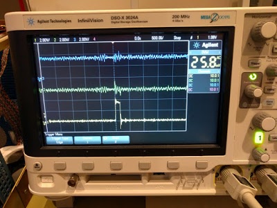
We connected logic analyzer probes so we could trace each chip in the bank select circuit. The PROM correctly generated the RAM bank signals when the SWMODE micro-instruction executed, but in the next step its inputs had reverted to the ROM bank for some reason. This showed the PROM worked, so we continued probing through the circuit. Each chip had the proper output until we got to the multiplexer chip that feeds back to the PROM. (This chip, on the right, handles microcode task switching by selecting either the current task's bank, or the new tasks's bank, which is recorded in a RAM chip.) The input signal to the multiplexer pulsed high for the new bank, but the output stayed low, blocking the bank switch signal. The oscilloscope trace below shows the problem: the input signal (bottom trace) is not passed to the output (middle trace).

A multiplexer IC in the Xerox Alto was failing to pass the bank switch signal from its input (bottom trace) to its output (middle trace).

A multiplexer IC in the Xerox Alto was failing to pass the bank switch signal from its input (bottom trace) to its output (middle trace).

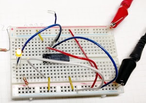
We found a bad chip on the disk interface board a few weeks ago, so had we located a second bad chip? We pulled out the suspicious chip (a 74S157 multiplexer) and tested it in a breadboard to prove that it was faulty. Surprisingly, it worked just fine. Perhaps the problem only showed up at high frequency? We swapped it with an identical chip on the board and the crash still happened. Clearly there was nothing wrong with the chip. But its output stayed low when it should go high. Why was this?

We thought this 74S157 multiplexer IC from the Xerox Alto was faulty. However, the chip worked fine when tested in a breadboard.

We thought this 74S157 multiplexer IC from the Xerox Alto was faulty. However, the chip worked fine when tested in a breadboard.

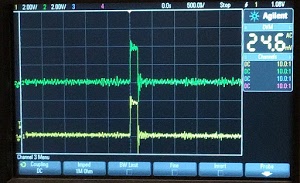
Our next theory was that something was grounding the chip's output signal, forcing the output to remain low. To test this, we disconnected the chip's output pin from the rest of the circuit by bending the pin so it didn't go into the socket, With the output not connected to the circuit, the output went high as expected. (See oscilloscope trace below.) This proved that the chip worked and something else was pulling the signal low. Since the chip's output was connected to the PROM chip, the obvious suspect was the PROM, which might have an input shorted low. We hoped the PROM chip wasn't at fault, since locating a 1970s-era D3601 PROM chip and reprogramming it would be inconvenient. We pulled the PROM chip out of the board and the short to ground remained, demonstrating the PROM chip was not the culprit.

With the multiplexer's output disconnected from the circuit, the input signal (bottom) appears on the output (top) as expected.

With the multiplexer's output disconnected from the circuit, the input signal (bottom) appears on the output (top) as expected.

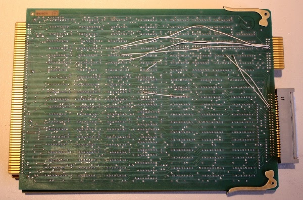
We removed the control board from the Alto to examine it for short circuits. On the back of the circuit board, we noticed that two white wires were connected to the multiplexer chip that was causing us problems. (Wires are added to printed circuit boards to fix manufacturing problems, support new features, or support new hardware.) These wires went to the connector that was cabled to the CRAM (control RAM) board shown earlier. With the CRAM board disconnected, the short to ground went away. Thus, the cause of our crashes was these two wires that someone had added to the board! Could we simply cut these wires and have the system work correctly? We figured we should understand why the wires were there, rather than randomly ripping them out. Maybe our control board and CRAM board were incompatible? Maybe these wires were to support the Trident disk drive we aren't using? It was the end of the day by this point, so further investigation will wait until next time.

This is the Xerox Alto control board, one of three boards that make up the CPU. The board has been modified with several white wires.

This is the Xerox Alto control board, one of three boards that make up the CPU. The board has been modified with several white wires which trigger our crashes.

Conclusion

After a bunch of software, microcode and hardware debugging we found that the crashes are due to some wires added to one of the circuit boards. These wires messed up microcode bank switching, causing programs that used custom microcode to crash. Fixing this should be straightforward, but we want to understand the motivation behind these wires. On the whole, the processor is working reliably other than this one issue. Once it is fixed, we can run MADTEST (the microcode test program) to stress-test the processor. If there are no more processor issues, we'll move on to getting the mouse working.

For updates on the restoration, follow me on Twitter at kenshirriff. Thanks to the Living Computer Museum for the extender board and the ContrAlto simulator.

Restoring Y Combinator's Xerox Alto, day 4: What's running on the system

This post describes our continuing efforts to restore a Xerox Alto. We checked that the low-level microcode tasks are running correctly and the processor is functioning. (The Alto uses an unusual architecture that runs multiple tasks in microcode.) Unfortunately the system still doesn't boot from disk, so the next step will be to get out the logic analyzer and see exactly what's happening. Here's Marc's video of the days's session:

The Alto was a revolutionary computer, designed at Xerox PARC to investigate personal computing, introducing the GUI, Ethernet and laser printers to the world. Y Combinator received an Alto from computer visionary Alan Kay. I'm helping restore the system, along with Marc Verdiell, Luca Severini, Ron Crane, Carl Claunch and Ed Thelen (from the IBM 1401 restoration team). For background, see my previous restoration articles: day 1, day 2, day 3.

Checking the clocks

We started by checked that all the clock signals were working properly by connecting an oscilloscope to the wirewrap pins on the computer's backplane. This took a lot of careful counting to make sure we connected to the right pins! The system clock signals are generated by an oscillator on the video display card, which isn't where I'd expect to find them. Since the clock signals control the timing of the entire system, nothing will happen if the clock is bad. Thus, checking the clock was an important first step.

At first, the clock signals all looked awful, but after finding a decent ground for the oscilloscope probes, the clock signals looked much better. We verified that the multiple clock outputs were all running nicely. We also tested the reset line to make sure it was being triggered properly - the Alto is reset by pushing a button at the back of the keyboard.

Connecting an oscilloscope to the Xerox Alto backplane

Connecting oscilloscope probes to the Xerox Alto backplane.

Microcode tasks

Next we looked at the running tasks. The Alto has 16 separate tasks running in microcode, doing everything from pushing pixels to the display to refreshing memory to moving disk words. Keep in mind that these are microcode tasks, not operating-system level tasks. The Alto was designed to reduce hardware by performing as many tasks in software as possible to reduce price and increase flexibility. The downside is the CPU can spend the majority of its time doing these tasks rather than "useful" work.

Alto task scheduling is fairly complex. Each task has a priority. When a task is ready to run, its request line is activated (by the associated hardware). The current task can offer to yield by executing the TASK function at convenient points. If there is a higher-priority task ready to run, it preempts the running task. If there's nothing better to run, task 0 runs - this task is what actually runs user code, emulating the Data General Nova instruction set.

The point of this explanation is that microcode instructions need to be running properly for task switching to happen. If the TASK function doesn't get called, the current task will run forever. And if all the task scheduling hardware isn't working right, task switching also won't happen.

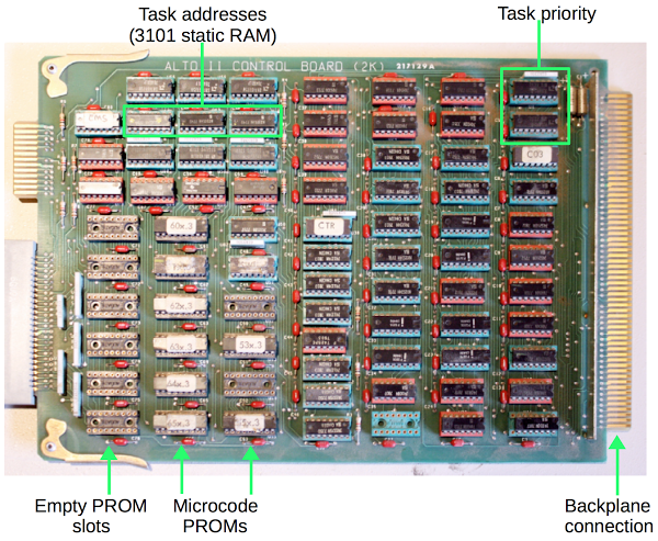
Below is a picture of the microcode control board from the Alto. When you're using 1973-era chips, it takes a lot of chips to do anything. This board manages which task is running and the memory address of each task. It uses two special priority encoder chips to determine which waiting task has the highest priority. The board holds the microcode, 1024 micro-instructions of 32 bits each, using eight 1K x 4 bit PROM chips. (PROM, programmable read-only memory, is sort of like non-erasable flash memory.) The board has 8 open sockets allowing an upgrade of 1K of additional microcode to be installed. Note the tiny memory capacity of the time, just 512 bytes of storage per chip.

The microcode control board from a Xerox Alto

The microcode control board from a Xerox Alto

Since tasks can be interrupted, the board needs to store the current address of each task. It uses two i3101A RAM chips for this storage. The 3101 is historically interesting: it was the first solid state memory chip, introduced by Intel in 1969. This chip holds 64 bits as 16 words of 4 bits each. Just imagine a time when a memory chip held not gigabits but just 64 total bits.

Looking at the running tasks

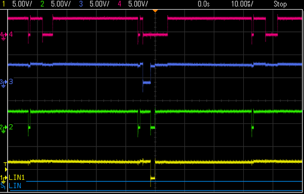
The control board has a 4-bit task number available on the backplane, indicating which task is running. We hooked up the oscilloscope so we could see the running tasks. The good news is we saw the appropriate tasks running at the right intervals, with preemption working properly. The following traces show the four task number bits. Most of the time the low-priority task 0 runs (all active-low signals high). Task 12 is running in the middle. Task 8 (memory refresh) runs three times, 38.08 microseconds apart as expected. From the traces, everything seems to be functioning correctly with the task execution.

The 4-bit microcode task select lines on the Xerox Alto

Trace of the 4-bit microcode task select lines on the Xerox Alto. Top (red) is 8, then 4, 2 and bottom (yellow) is 1 bit. Signals are active-low. Each time interval is 10 microseconds, so this shows a 100 microsecond time interval.

Seeing the running tasks is a big thing, since it shows a whole lot of the system is working properly. As explained earlier, since tasks are running and switching, the microcode processor must be fetching and executing micro-instructions correctly.

Display working better now

You may remember from the previous article that the Alto display was very, very dim and we suspected the CRT was failing. The good news is the display has steadily increased in brightness from its original very dim state, so we probably won't need to replace the CRT. We also managed to see some garbage on the screen along with a cursor, showing that RAM is storing something and the display interface is working.

The display of the Xerox Alto displaying random junk.

The display of the Xerox Alto displaying random junk.

Boot still doesn't work

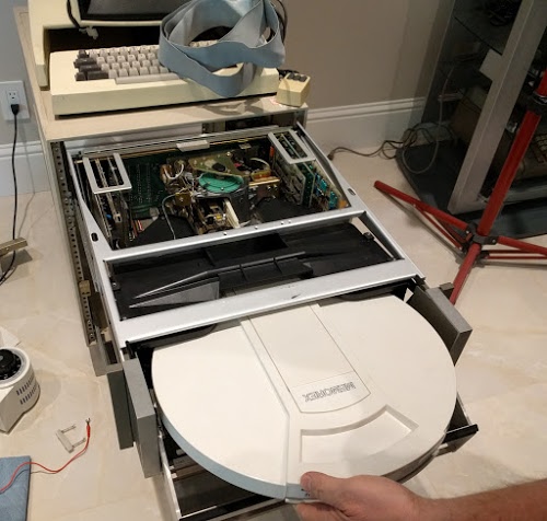
Lots of things are working at this point. The minor :-) remaining problem is the system doesn't boot. Last time, we got the disk drive working: we can put a 14-inch disk cartridge (below) in the drive, the drive spins up, and the heads load. But looking at the backplane signals, we found nothing is getting read from the disk (which explains the boot failure). The oscilloscope showed that the Alto isn't sending any commands to the disk - the Alto isn't even trying to read the disk. We checked for various hardware issues and couldn't find any problems. My suspicion is the boot code in microcode isn't running properly.

Inserting a hard disk into the Diablo drive.

Inserting a hard disk into the Diablo drive.

A bit of explanation on the boot process: On reset, microcode task 0 handles the boot. If backspace is pressed on the keyboard, the Alto does a Ethernet boot. Otherwise it does a disk boot by setting up a disk command block in RAM. The microcode disk sector task gets triggered on each sector pulse (which we saw coming from the disk). It checks if there is a command block in RAM, and if so sends the command to the disk. When the read data comes from the disk, the disk word task copies the data into memory. At the end, the block read from disk will be executed, performing the disk boot. So three microcode tasks need to cooperate to boot from disk.

Since we're seeing no command sent to the disk, something must be going wrong between task 0 setting up the command block in RAM and the sector task executing the command block. There's a lot that needs to go right here. If anything is wrong in the ALU or RAM has problems, the command block will get corrupted. And then no disk operation will happen.

Conclusion

The next step is to use a logic analyzer to see exactly what is running, instruction by instruction. By looking at the microcode address lines, we will be able to see what code is executing and where things go wrong. Then we can probe the memory bus to see if RAM is the problem, and look at the ALU to see if it is causing the problem. This is where debugging will get more complex.

I've studied the microcode and it is very bizarre. (You can see the source here.) Instructions are in random order in the PROM, what an instruction does depends on what task is running, branches happen when a device board flips address bits on the bus, and some bits in the PROM are inverted for no good reason (probably to save an inverter chip somewhere). So looking at the microcode can be mind-bending. But hopefully with the logic analyzer we can narrow the problem down. We can also use the Living Computer Museum's simulator to cross-check against what microcode should be running.

For updates on the restoration, follow kenshirriff on Twitter.

iPad charger teardown: inside Apple's charger and a risky phony

Apple sells their iPad charger for $19, while you can buy an iPad charger on eBay for about $3. From the outside, the chargers look the same. Is there a difference besides the price? In this article, I look inside real and counterfeit chargers and find that the genuine charger has much better construction, power quality, and most importantly safety. The counterfeit turns out to be a 5 watt charger in disguise, half the power of a genuine charger.

iPad
Counterfeit
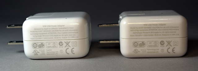
A real Apple iPad charger (left) and a counterfeit charger (right

From the outside, the real charger (left) and counterfeit charger (right) are almost identical. If you look very closely, you can spot are a few differences in the text: The counterfeit removed "Designed by Apple in California. Assembled in China" and the manufacturer "Foxlink"[1], probably for legal reasons. (But strangely, the counterfeit still says "TM and © 2010 Apple Inc.") The counterfeit charger displays a bunch of certifications (such as UL) that it doesn't actually have. As you will see below, there is no way it could pass safety testing.

Opening up the chargers reveals big differences between them. The genuine charger on the left is crammed full of components, fitting as much as possible into the case. The counterfeit charger on the right is much simpler with fewer components and much more empty space. The Apple charger uses larger, higher-quality components (in particular the capacitors and the transformer); below you will see that these have a big effect on power quality and safety.

iPad
Counterfeit
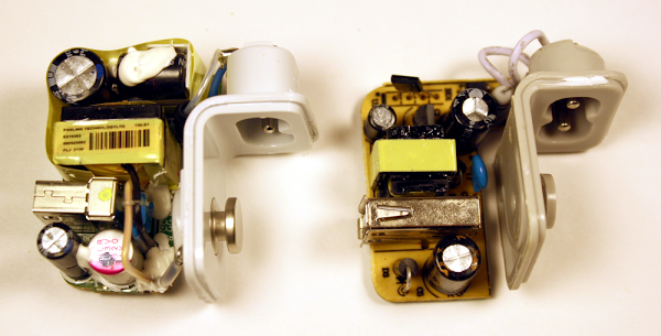
The components inside a real iPad charger (left) and a counterfeit charger (right).

The components inside a real iPad charger (left) and a counterfeit charger (right).

One safety difference is obvious: the Apple charger has much more insulation. The upper (high-voltage) half is wrapped in yellow insulating tape. Some components are encased in shrink tubing, there are plastic insulators between some components, and some wires have extra insulation. The counterfeit charger only has minimal insulation.

The build quality of the Apple charger is much higher. In the counterfeit charger, some components are visibly crooked or askew. While this doesn't affect the circuit electrically, it indicates a lack of care in construction.

Flipping the boards over reveals that the circuitry of the genuine Apple charger is much more complex than the counterfeit. The Apple board is crammed with tiny surface-mounted components in every available spot. The counterfeit board has a lot of empty space, with just a few components. Note the reddish insulating tape in the lower center of the Apple board, another safety feature of the genuine charger.

iPad
Counterfeit
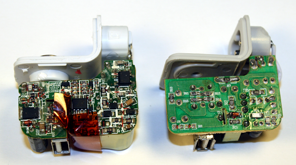
The circuit board of a real iPad charger (left) and a counterfeit charger (right).

The circuit board of a real iPad charger (left) and a counterfeit charger (right).

How the chargers work

Both the real and counterfeit chargers use similar flyback[2] switching power supply circuits. The switching power supply is the innovation that allows these chargers to be so compact, unlike the heavy "wall warts" powering older consumer electronics. The principle of a switching power supply is the power is switched on and off tens of thousands of times a second, allowing it to provide the exact amount of power required with very little power wasted as heat. In addition, the high frequencies allow the charger to use a small transformer, unlike the bulky transformers used for 60 Hz AC.

Since the counterfeit charger is much simpler, it is easier to understand how it works and I'll explain it first in reference to the picture below. The AC power enters through the white wires in the upper left. It passes through a fusible resistor, which acts as a safety fuse. Below this, the bridge rectifier contains four diodes which convert the AC into DC (at about 170 to 340 volts[3]). The input capacitor smooths out this power. The 4-pin control IC[4] monitors the charger and uses the switching transistor to turn the high-voltage DC on and off 41,000 times per second. This chopped DC is fed into the primary winding of the flyback transformer. The transformer converts this to the desired high-current 5 volts. The output diode produces DC, and the output capacitor smooths it out. Finally, the output voltage is available at the USB connector to power your iPad. A few components round out the circuit. A feedback winding on the transformer provides voltage feedback to the control IC. This winding also powers the IC; the IC power capacitor smooths out this power. Finally, the blue snubber[5] capacitor absorbs current spikes when the transistor is switched off.[6]

Counterfeit
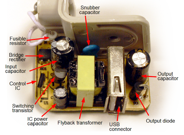
Inside a counterfeit iPad charger

Inside a counterfeit iPad charger

The genuine iPad charger below operates on similar principles, although the circuit is more advanced. The AC input is on the lower right, and goes through a 2A fuse (in black insulation for safety). The primary has much more filtering than in the counterfeit charger with a filter coil (common mode choke), inductor, and two large electrolytic capacitors. This increases the cost, but improves the power quality. On the output side (left), the charger has two filter capacitors, including a high-quality aluminum polymer capacitor (with the magenta stripe). The Y capacitors help reduce interference.[7] The tiny NTC temperature sensor lets the charger shut down if it overheats. (I removed some of the charger's insulation to make the components visible in this photo.)

iPad
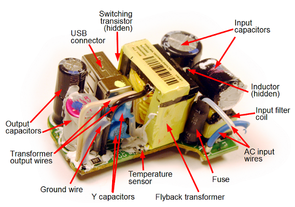
Inside a genuine iPad charger.

Inside a genuine iPad charger.

On the other side of the circuit board, things get complicated in the Apple charger. Starting with the AC input in the upper right, the charger includes additional input filters as well as spark gaps.[8] The latch release circuit[9] lets the charger reset quickly from faults. The control IC[10] provides advanced control of the charger under varying conditions. (This IC is much more complex than the control IC in the counterfeit charger.) The current sense resistor lets the IC monitor the current through the transformer and the line voltage resistors let the IC monitor the input voltage (as well as initially powering-up the IC[9]). The protection circuit uses the temperature sensor on the other side of the board to shut down if there is an over-voltage or over-temperature problem. [20]

iPad
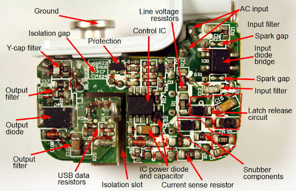
The circuit board inside a genuine iPad charger showing the components.

The circuit board inside a genuine iPad charger showing the components.

The secondary side includes some special features for power quality. The Y-capacitor filter works with the Y capacitors to filter out noise. The output filter circuitry is more complex than in the counterfeit. Note that the real charger has a ground connection, unlike the counterfeit charger which has a plastic pin here.[11]

Both chargers use resistors to put special voltages on the USB data lines[12] to indicate the charger type, using Apple's proprietary system (details). (This is why iPads say "Charging is not supported with this accessory" with some chargers.) Through these resistors the genuine charger indicates that it is an Apple 2A charger, while the counterfeit indicates that it is an Apple 1A charger. This shows that the counterfeit is really a 5W charger packaged as a 10W charger.

When looking at these circuits up close, it's easy to forget just how small the components are. The picture below shows one of the surface-mount components (a 0-ohm resistor[13]) from the iPad charger. It is just to the left of Roosevelt's chin on the dime.

A zero-ohm resistor from the iPad charger, on top of a dime

A zero-ohm resistor

Safety, or lack thereof

Safety probably isn't something you think about when you plug in your charger, but it's important. Inside the charger is 170 volts or more with very little separating it from your iPad and you. If something goes wrong, the charger can burn up (below), injure you, or even kill you. Devices such as chargers have strict safety standards[14] - if you get a charger from a reputable manufacturer. If you buy a cheap counterfeit charger, these safety standards are ignored. You can't see the safety risks from the outside, but by taking the chargers apart, I can show you the dangers of the counterfeit.

Counterfeit iPhone
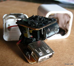
Counterfeit iPhone charger that burned up
A Counterfeit iPhone charger that burned up. Photo by Anool Mahidharia. Used with permission

Creepage and clearance

The UL regulations[14] require safe separation between the high voltage and the low voltage. This is measured by creepage - the distance between them along the circuit board, and clearance - the distance between them through air. The regulations are complex, but in general there should be at least 4mm between high-voltage circuitry and low-voltage circuitry.

iPad
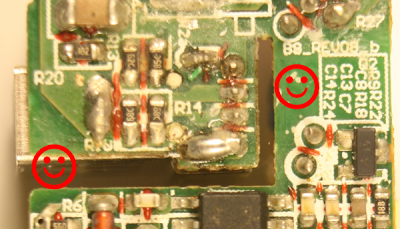
The iPad charger provides safe creepage and clearance distances between the high-voltage side (bottom) and low-voltage side (top).

The iPad charger provides safe creepage and clearance distances between the primary high-voltage side (bottom) and secondary low-voltage side (top).

The image above shows how the genuine iPad charger's circuit board separates the high voltage (bottom) from the low voltage (top). The happy face on the right marks an empty region that provides a safety gap between the primary and secondary. (This is a contrast with the rest of the circuit board, which is crammed full of components.) This gap of 5.6mm provides a comfortable safety margin. The happy face on the left marks a slot in the board that separates the low voltage and high voltage. The photo below shows how an insulating fin is built into the case and through this slot to protect the USB connector. Additional reddish-brown insulating tape goes through this slot, and the whole high-voltage section is wrapped in yellow insulating tape. The result is multiple layers of protection.

iPad
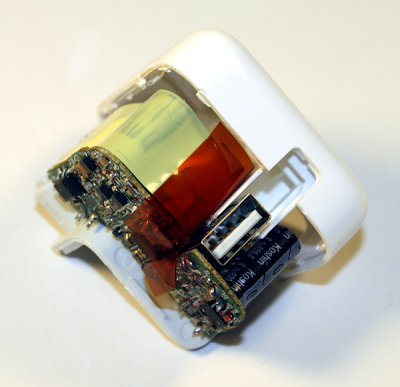
The iPad charger case has a plastic fin that slides around the USB port to provide extra insulation.

The iPad charger case has a plastic fin that slides around the USB port to provide extra insulation.

The creepage distance on the counterfeit charger board below is scary - only 0.6 mm separation between low and high voltage. The sad face on the right shows where a low-voltage trace is nearly touching the high-voltage trace below. (The ruler on the right indicates millimeters.) The board isn't as bad as it could be: the happy face on the left marks a slot cut in the circuit board under the transformer to increase the creepage distance. But overall, this board is unsafe. If you use the charger in a humid bathroom and a drop of water condenses across the 0.6 mm gap, then zap!

Counterfeit
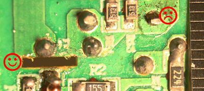
Dangerous creepage in a counterfeit iPad charger.

Dangerous creepage in a counterfeit iPad charger.

Safety in the transformer

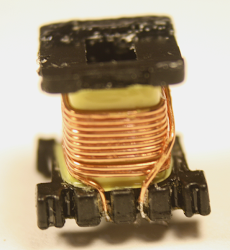
For safety, the high-voltage and low-voltage sides of the charger must be electrically isolated.[15] But obviously the electrical power needs to get through somehow. The flyback transformer accomplishes this task by using magnetic fields to transfer the power without a dangerous direct connection. Because the transformer is a large and relatively expensive component, it is tempting to take safety and quality short cuts here. The genuine transformer (left) is considerably larger than the counterfeit (right), which is a hint of better quality and more power capacity. Disassembling the transformers shows that this is the case.

iPad
Counterfeit
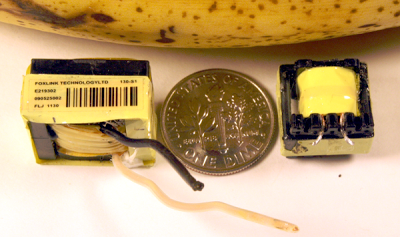
The flyback transformers from an iPad charger (left) and a counterfeit charger (right). Dime and banana are for scale.

The flyback transformers from an iPad charger (left) and a counterfeit charger (right). Dime and banana are for scale.

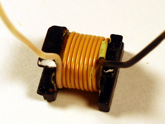
The key safety requirement of the transformer is to separate the high-voltage windings from the low-voltage secondary winding, and the counterfeit charger fails here. The pictures below show the transformers after removing primary windings and insulating tape, revealing the secondary winding. The wires look similar at first glance, but the the genuine charger (left) has triple-insulated wire while the counterfeit (right) is uninsulated except for a thin varnish. The triple-insulated wire is an important safety feature that keeps the high voltage out even if there is a flaw in the insulating tape and in the wire's insulation. Also note the additional black and white insulation on the wires where they leave the transformer. In the counterfeit charger, the only thing separating the secondary winding from high voltage is the insulating tape. If there is a flaw in the tape or the wires shift too far, then zap!

iPad
Inside the transformer of an iPad charger, This is the triple-insulated secondary winding.
Counterfeit
The secondary winding does not have triple-insulated wiring. This is a major safety flaw in the counterfeit iPad charger.

The real charger provides much more power with much less noise

Lab measurements of the output from the chargers shows a couple problems with the counterfeit. First, the counterfeit turns out to provide at most 5.9W, not 10W. Second, the output voltage is extremely noisy and full of spikes.

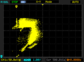
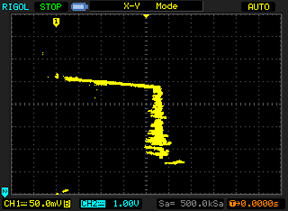
The following voltage-vs-current graphs show the performance of the iPad charger (left) and counterfeit charger (right) under increasing load. The line for the real charger goes much farther to the right, showing that the real charger provides much more current. By my measurements, the real charger provides a maximum of 10.1 watts, while the counterfeit charger provides only 5.9 watts. The consequence is the real charger will charge your iPad almost twice as fast. (For details on these graphs, see my article testing a dozen chargers.) The other thing to note is the line for the Apple charger is smooth and thin, while the counterfeit charger's line is all over the place. This indicates that the power provided by the counterfeit charger is noisy and low quality.

iPad
Voltage vs current graph for iPad charger
Counterfeit
Voltage vs current graph for fake iPad charger

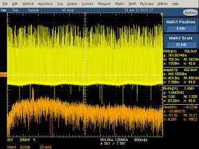
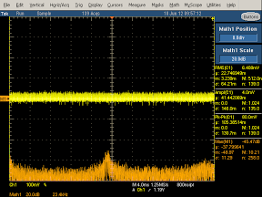
The next pair of graphs shows the power quality. The yellow line shows the voltage. The real charger has a stable yellow thin line, while the counterfeit charger's output has large voltage spikes. (I had to change the scale to get the output to fit on the screen, so the counterfeit charger is actually twice as bad as it appears here.) The bottom of the counterfeit charger's yellow line is wavy, due to 120 Hz ripple appearing in the output voltage.

iPad
High frequency oscilloscope trace from Apple iPad charger
Counterfeit
High frequency oscilloscope trace from counterfeit iPad charger

The orange line shows the frequency spectrum of the output: lower is better, and higher is exponentially worse. The counterfeit spectrum is much higher in general, with a large spike at the switching frequency. This shows that the counterfeit charger's power is worse across the frequency spectrum.

You might wonder if the power quality actually matters. The biggest impact it has is on touchscreen performance. The interference from bad power supplies is known to cause the touchscreen to behave erratically.[16] If your screen malfunctions when plugged into a charger, this is probably the cause.

Inside the real charger's transformer

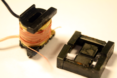
There's more inside the transformer that you'd expect. This section does a full teardown of the transformer from the genuine charger.

iPad
A copper band surrounds the ferrite core in the flyback transformer from an iPad charger.
iPad
Removing the ferrite core and insulation reveals the double-stranded primary winding.

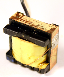
The first photo above shows that underneath the the first layer of yellow insulating tape, a layer of copper foil is attached to the transformer's ferrite core to ground it. Next, removing the ferrite core and more insulation reveals the double-stranded primary winding. The high-voltage input is fed into this winding.

iPad
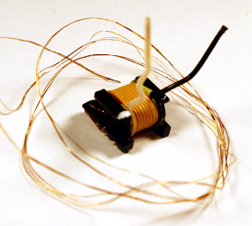
After removing the triple-stranded bias winding and insulating tape, the secondary winding of the transformer is visible. Note the triple-insulated wires used for the secondary winding.
iPad
The next layer of insulation contains copper foil.

Underneath the primary winding and more insulating tape is the triple-stranded bias winding, which provides feedback and power to the control IC. (In the photo, this winding has been removed and is surrounding the transformer.) After removing more insulating tape, the secondary winding of the transformer is visible. As discussed in the safety section, the secondary winding has triple-insulated wires and extra insulation where the wires leave the transformer. The next layer of insulation (right) contains copper foil. This helps reduce interference.

iPad
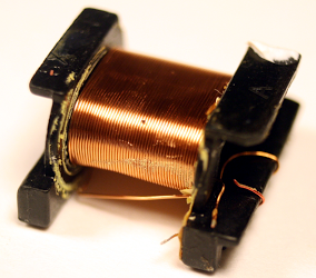
The innermost layer of the iPad charger flyback transformer is the primary winding.

Finally, the innermost layer of the iPad charger flyback transformer is the second half of the primary winding (above). Splitting the primary winding into two layers is more expensive, but results in a better transformer due to better coupling of the magnetic fields.

In comparison, the transformer of the counterfeit charger is much lower quality. (I haven't included the pictures for reasons of space; click through to see them.) It simply has the bias winding (pic), secondary winding (pic), and primary winding (pic) , separated by insulating tape. Unlike the genuine transformer, the counterfeit saves cost by omitting the copper foil layers. The counterfeit also doesn't use the more expensive split, multi-stranded windings that the genuine charger uses. As discussed earlier, the secondary winding is plain copper wire, not triple-insulated wire, which is a significant safety flaw.

How does the iPad charger compare to the iPhone charger?

The iPad charger is considerably larger than the iPhone charger and provides twice the power. In my detailed iPhone charger teardown I looked at the internals of the iPhone charger. The iPhone charger (below) uses two circuit boards that combine to form a one inch cube, which is impressive engineering. The iPhone and iPad chargers are both flyback switching power supplies, but the feedback mechanisms are very different.[17] Overall, I like the iPhone charger more than the iPad charger from a design standpoint, mainly because of the harder engineering challenge of cramming everything into a much smaller space.

iPhone
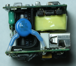
Inside the iPhone charger: input inductor (green), Y capacitor (blue), flyback transformer (yellow), USB connector (silver). The primary circuit board is on top and the secondary board on the bottom.

Schematics

In my iPhone charger teardown, I drew up a schematic of the charger, but for the iPad chargers I didn't need to do this. The genuine iPad charger is almost identical[18] to the reference design schematic provided by iWatt. The counterfeit charger is almost identical to the schematic in the DB02A controller datasheet. You can see from the schematics that the genuine charger has a much more complex circuit than the counterfeit. (Click the thumbnails below to get to the datasheets.)

iPad
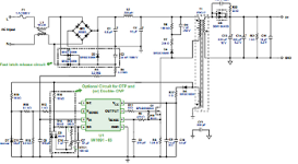
Thumbnail: Click for schematic of iPad charger based on iWatt 1691 controller.
Counterfeit
Thumbnail: Click for schematic of counterfeit iPad charger based on DB02A controller.

Is the Apple charger worth the price?

Apple's charger is expensive compared to other chargers, but is a high quality product. You should definitely stay away from the cheap counterfeit chargers, as they are low quality and dangerous. Non-Apple name brand chargers are generally good quality according to my tests, with some better than Apple. If you want to get an Apple charger without the high price, the best way I've found is to buy a used one on eBay from a US source. I've bought several for testing, and they have always been genuine.

I wrote earlier about Apple's huge profit margins on chargers. Apple has since dropped their charger prices from $29 to $19, which is more reasonable, but looking at the price of similar chargers from other manufacturers and the cost of components, I think Apple has a huge profit margin even at $19.[19]

In any case, the iPad charger is an impressive piece of engineering with a lot of interesting circuitry inside. The counterfeit charger is also impressive in its own way - it's amazing that a charger can be manufactured and sold for such a low price (if you don't care about safety and quality). Overall, you mostly get what you pay for; even if you can't tell from the outside, there are big differences inside the case.

Notes and references

[1] Foxlink (Taiwan), Foxconn (Taiwan), and Flextronics (Singapore) are all manufacturers for Apple with confusingly similar names. Foxconn is the company with controversy over employee treatment; this charger is made by Foxlink, a different company. Interestingly, the chairmen of both companies are brothers and the companies do a lot of business with each other. The companies state that they are entirely independent, though (statement, Foxlink annual report). Foxconn and Flextronics are the world's #1 and #3 largest electronics manufacturing companies according to the MMI top 50 for 2013, while Foxlink is smaller.

[2] The chargers uses a flyback design, where the transformer operates "backwards" from how you might expect. When a voltage pulse is sent into the transformer, the output diode blocks the output so there is no output - instead a magnetic field builds up in the transformer. The transformer core has a tiny air gap to help store this field. When the voltage input stops, the magnetic field collapses, transferring power to the output winding. Flyback power supplies are very common for low-wattage power supplies.

[3] You might wonder why the DC voltage inside the power supply is so much higher than the line voltage. The DC voltage is approximately sqrt(2) times the AC voltage, since the diode charges the capacitor to the peak of the AC signal. Thus, the input of 100 to 240 volts AC is converted to a DC voltage of 145 to 345 volts internally. This isn't enough to be officially high voltage but I'll call it high voltage for convenience. According to standards, anything under 50 volts AC or 120 V dc is considered extra-low voltage and is considered safe under normal conditions. But I'll refer to the 5V output as low voltage for convenience.

[4] The counterfeit charger uses a DB02A controller IC. This controller only has four pins and is in a TO-94 (SIP-4) package. (According to the official JEDEC standard, TO-94 is a bolt-like package for large SCRs. It's a puzzle why some companies use TO-94 to describe 4-pin inline packages.) According to the datasheet (Chinese), the chip is for 500mA-1000mA chargers, which explains why the counterfeit charger only produces 5 watts, instead of the 10 watts an iPad charger is supposed to produce. This controller is very inexpensive, available for ¥ 0.35 (about 6 cents).

I couldn't find any US chips similar to this chip, even after a lot of searching; it appears to be a Chinese design with datasheets only in Chinese, manufactured by "Fine Made" Shenzhen Fuman Electronics. Since the chip only has four pins, I expected it to be a trivial Ringing Choke Converter (RCC) circuit with just a couple transistors inside the chip - but I cracked it open with Vise-Grips and it turns out to be a fairly complex chip. I took a picture through a microscope of the IC die, which is about 1 mm across. One interesting feature is the many white pads around the outside of the die, which are used to blow fuses to trim various resistances in the chip. I wasn't expecting to see this level of quality and sophistication. The die has the label "N7113 802" at the right; I don't know what this indicates. Three of the four wires connect in the lower left, and the fourth in the lower right.
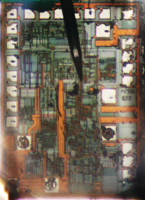
Die photo of the DB02A SMPS controller chip.

Die photo of the DB02A SMPS controller chip used in the counterfeit charger.

[5] When a diode or transistor switches, it creates a voltage spike, which can be controlled by a special snubber or clamp circuit. For a lot of information on snubbers and clamps, see Passive Lossless Snubbers for High Frequency PWM Conversion and Switchmode Power Supply Reference Manual.

[6] In the counterfeit charger, the switching transistor is a ALJ 13003 NPN power transistor (datasheet), apparently made by Shenzhen LongJing Microelectronics Co. This transistor is a version of Motorola's MJE 13003 switchmode transistor which was introduced in 1976 (MJE indicates power device in a plastic package). The bridge rectifier is a B6M (datasheet). The output diode is a SR260 Schottky barrier rectifier.

[7] The iPad charger uses special Y-capacitors to bridge the high-voltage and low-voltage sides of the charger. This capacitor helps reduce EMI interference, and is specially designed to avoid any safety hazard. It does, however, pass a tiny amount of electricity - if you feel a tingle from your charger, these capacitors are probably the cause. For more information on X and Y capacitors, see Kemet's presentation and Designing low leakage current power supplies.

[8] The iPad has two spark gaps next to inductor L1 (the input AC common mode choke). I couldn't find a lot of information on this sort of spark gap, but one example of it is an Infineon SMPS design, where similar spark gaps are designed to discharge accumulated charge for a 3KV lightning surge test.

[9] The Apple charger includes a "latch release circuit". If there is a fault, the control IC will shut down the charger until power is removed. However, after unplugging a charger, the input capacitors may store power for many seconds. (You may have seen LEDs remain illuminated for several seconds after unplugging devices.) The latch release circuit ensures that the charger will reset properly even if you plug it back in quickly. It does this by providing a separate diode bridge for the charger's power - this circuit has a much smaller capacitor, so it will power off quickly. (See the schematic for details.) This seems like over-engineering to me, adding extra circuitry for this rare case.

In normal use, by the way, the control IC is powered by the transformer's feedback winding. But if the control IC isn't running, the transformer won't work, leading to a chicken-and-egg situation. The solution is a startup power path where the control IC gets enough power from the AC input to start up, and then switches to the transformer.

[10] The genuine charger uses a complex control chip manufactured by iWatt, the 1691. This chip monitors the input line voltage, the current through the transformer, and the voltage feedback from the transformer. It controls the switching frequency and length of time the power is switched on, with different behavior under no load, low load, and high load, as well as constant monitoring for faults. A detailed presentation on the iW1691 is here. This chip sells for about 30 cents, but I expect Apple gets a better price.

[11] The real charger has a metal ground pin that connects to the power plug, while the counterfeit has a plastic pin. This is one difference between the chargers that is visible externally if you slide the power plug off the charger. Ironically, the US plug doesn't use the ground connection, so this is one safety issue that doesn't make any difference in practice.

[12] Apple uses a proprietary technique for the charger to indicate to the device what kind of charger it is. Different types of Apple chargers use resistances to put different voltages on the USB D+ and D- pins. For details on USB charging protocols, see my earlier references.

[13] While it would be nice to find superconductors inside the charger, unfortunately the zero-ohm resistor is a bit more than 0 ohms. While this resistor may seem pointless, it allows the manufacturers to substitute a resistor later if different transistors require it.

[14] The outside of the charger has the slightly mysterious text: "For use with information technology equipment". This indicates that the charger is covered by the safety standard UL 60950-1, which specifies the various isolation distances required. For a brief overview of isolation distances, see i-Spec Circuit Separation and some of my earlier references.

[15] Only a few special components can safely bridge the gap between the high voltage side of the charger and the low voltage side. The most obvious is the transformer. Y-capacitors can also bridge the primary and secondary side because they are designed not to pass dangerous currents, and not to short out if they fail. Optoisolators use a light signal to provide feedback between the circuits in an iPhone charger, but are not used in the iPad charger.

[16] For an explanation of why the noisy output from cheap chargers messes up touchscreens, see Noise Wars: Projected Capacitance Strikes Back. The article discusses how capacitive touchscreen ICs need to sense pico-Coulombs of charge, which is very difficult when AC noise is present. The article blames touchscreen problems on aftermarket low cost chargers.

[17] The biggest difference between the iPhone charger and the iPad charger is the feedback used to regulate the voltage. The iPhone charger measures the output voltage with a TL431 chip and sends a feedback signal to the control IC via an optoisolator. The iPad charger avoids these components by using primary-side regulation. Instead of measuring the actual output voltage, the iPad control IC looks at the voltage in the feedback winding, which should approximately match the output voltage.

[18] I noticed only a few significant differences between the iPad charger and iWatt's published 1691 charger reference design. This probably means iWatt did most of the design work for Apple.

Comparing the actual charger with the reference design shows a few filtering improvements. The charger has RC snubbers the input bridge rectifier (a rare feature also in the iPhone charger). The charger has an extra diode on the secondary for filtering, as well as a (zener?) diode in the switching transistor drive circuit. The iPad charger uses two Y-capacitors instead of one, and a R/C filter attached to the Y-capacitor on the secondary side. The charger connects line ground to secondary ground through a resistor. The reference design doesn't show the USB data resistors[12].

[19] Some people think that I'm ignoring Apple's cost of designing chargers when figuring their large profit margin. First, if you spend $2 million on design and manufacture 200 million chargers, then design adds only one cent to the cost per charger. Second, iWatt's designers deserve credit for the complex control chip and the reference design, which is most of the design work.

[20] For those interested in the components, the iPad charger's primary diodes (F6w) are 1.5A 60V Schottky Barrier Diodes (datasheet). The "T3" diodes are fast switching diodes (datasheet). The switching transistor is an Infineon SPA04N60C Cool MOS® 650V power transistor (datasheet). The bridge rectifier is a bridge: MB10S CD 0.5A bridge rectifier with high surge capacity (datasheet). The component in the protection circuit that looks like a transistor is a BAV70 dual high-speed switching diode (datasheet). The output diode is a SBR10U45SP5 10A super barrier rectifier (datasheet). The Y capacitors are 220pF 250V. The input capacitors are Samxon 10µFand 4.7µF 400v electrolytics. The output capacitors are a Koshin KLH 820µF 6.3V aluminum electrolytic, and a 820 µF 6.3V X-CON ULR aluminum polymer capacitor (which is more expensive than a regular electrolytic, but filters better because of its lower ESR).

Four Rigol oscilloscope hacks with Python

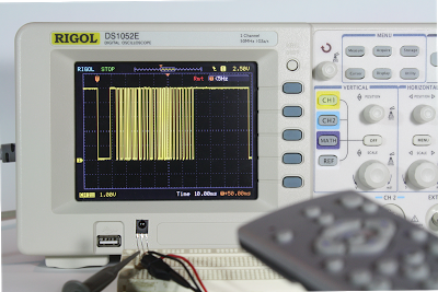
A Rigol oscilloscope has a USB output, allowing you to control it with a computer and and perform additional processing externally. I was inspired by Cibo Mahto's article Controlling a Rigol oscilloscope using Linux and Python, and came up with some new Python oscilloscope hacks: super-zoomable graphs, generating a spectrogram, analyzing an IR signal, and dumping an oscilloscope trace as a WAV file. The key techniques I illustrate are connecting to the oscilloscope with Windows, accessing a megabyte of data with Long Memory, and performing analysis on the data.

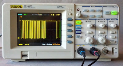
Analyzing the IR signal from a TV remote using an IR sensor and a Rigol DS1052E oscilloscope.

Analyzing the IR signal from a TV remote using an IR sensor and a Rigol DS1052E oscilloscope.

Super-zoomable graphs

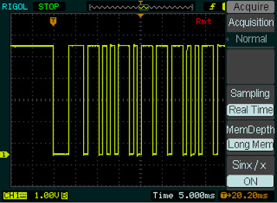
One of the nice features of the Rigol is "Long Memory" - instead of downloading the 600-point trace that appears on the screen, you can record and access a high-resolution trace of 1 million points. In this hack, I show how you can display this data with Python, giving you a picture that you can easily zoom into with the mouse.

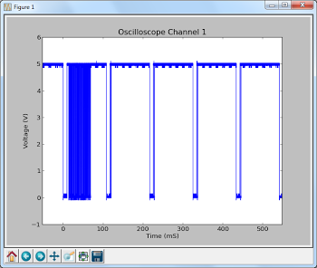
The following screenshot shows the data collected by hooking the oscilloscope up to an IR sensor. In the above picture, the sensor is the three-pin device below the screen. Since I've developed an IR library for Arduino, my examples focus on IR, but any sort of signal could be used. By enabling Long Memory, we can download not just the data on the screen, but 1 million data points, allowing us to zoom way, way in. The graph below shows what it sent when you press a button on the TV remote - the selected button transmits a code, followed by a periodic repeat signal as long as the button is held down.

The IR signal from a TV remote. The first block is the code, followed by period repeat signals while the button is held down.

The IR signal from a TV remote. The first block is the code, followed by period repeat signals while the button is held down.
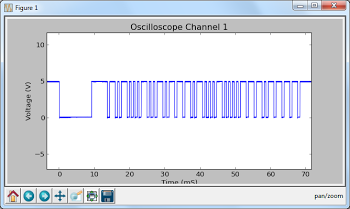
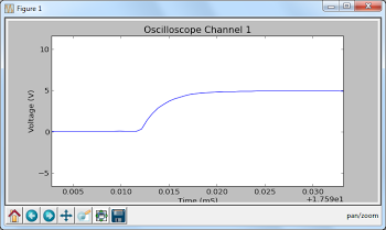
But with Long Memory, we can interactively zoom way on the waveform and see the actual structure of the code - long header pulses followed by a sequence of wide and narrow pulses that indicate the particular button. That's not the end of the zooming - we can zoom way in on an edge of a pulse and see the actual rise time of the signal over a few microseconds. You can do some pretty nice zooming when you have a million datapoints to plot.

Zooming in on the first part of the waveform shows the structure of the code - long header pulses followed by wide and narrow pulses. Zooming way, way in on the edge of a pulse shows the rise time of the signal.

To use this script, first enable Long Memory by going to Acquire: MemDepth. Next, set the trigger sweep to Single. Capture the desired waveform on the oscilloscope. Then run the Python script to upload the data to your computer, which will display a plot using matplotlib. To zoom, click the "+" icon at the bottom of the screen. This lets you pan back and forth through the data by holding down the left mouse button. You can zoom in and out by holding the right mouse button down and moving the mouse right or left. The magnifying glass icon lets you select a zoom rectangle with the mouse. You can zoom on your oscilloscope too, of course, but using a mouse and having labeled axes can be much more convenient.

A few things to notice about the code. The first few lines get the list of instruments connected to VISA and open the USB instrument (i.e. your oscilloscope). The timeout and chunk size need to be increased from the defaults to download the large amount of data without timeouts.

Next, ask_for_values gets various scale values from the oscilloscope so the axes can be labeled properly. By setting the mode to RAW we download the full dataset, not just what is visible on the screen. We get the raw data from channel 1 with :WAV:DATA? CHAN1. The first 10 bytes are a header and should be discarded. Next, the raw bytes are converted to numeric values with Mahto's formulas. Finally, matplotlib plots the data.

There are a couple "gotchas" with Long Memory. First, it only works reliably if you capture a single trace by setting the trigger sweep to "single". Second, downloading all this data over USB takes 10 seconds or so, which can be inconveniently slow.

Analyze an IR signal

Once we can download a signal from the oscilloscope, we can do more than just plot it - we can process and analyze it. In this hack, I decode the IR signal and print the corresponding hex value. Since it takes 10 seconds to download the signal, this isn't a practical way of using an IR remote for control. The point is to illustrate how you can perform logic analysis on the oscilloscope trace by using Python.

This code shows how the Python script can wait for the oscilloscope to be triggered and enter the STOP state. It also shows how you can use Python to initialize the oscilloscope to a desired configuration. The oscilloscope gets confused if you send too many commands at once, so I put a short delay between the commands.

Generate a spectrogram

Another experiment I did was using Python libraries to generate a spectrogram of a signal recorded by the oscilloscope. I simply hooked a microphone to the oscilloscope, spoke a few words, and used the script below to analyze the signal. The spectrogram shows low frequencies at the bottom, high frequencies at the top, and time progresses left to right. This is basically a FFT swept through time.

A spectrogram generated by matplotlib using data from a Rigol DS1052E oscilloscope.

A spectrogram generated by matplotlib using data from a Rigol DS1052E oscilloscope.
To use this script, set up the oscilloscope for Long Memory as before, record the signal, and then run the script.

Dump data to a .wav file

You might want to analyze the oscilloscope trace with other tools, such as Audacity. By dumping the oscilloscope data into a WAV file, it can easily be read into other software. Or you can play the data and hear how it sounds.

To use this script, enable Long Memory as described above, capture the signal, and run the script. A file channel1.wav will be created.

How to install the necessary libraries

Before connecting your oscilloscope to your Windows computer, there are several software packages you'll need.
  • I assume you have Python already installed - I'm using 2.7.3.
  • Install NI-VISA Run-Time Engine 5.2. This is National Instruments Virtual Instrument Software Architecture, providing an interface to hardware test equipment.
  • Install PyVISA, the Python interface to VISA.
  • If you want to run the graphical programs, install Numpy and matplotlib.
You can also use Rigol's UltraScope for DS1000E software, but the included NI_VISA 4.3 software doesn't work with pyVisa - I ended up with VI_WARN_CONFIG_NLOADED errors. If you've already installed Ultrascope, you'll probably need to uninstall and reinstall NI_VISA.

If you're using Linux instead of Windows, see Mehta's article.

How to control and program the oscilloscope

Once the software is installed (below), connect the oscilloscope to the computer's USB port. Use the USB port on the back of the oscilloscope, not the flash drive port on the front panel.

Hopefully the code examples above are clear. First, the Python program must get the list of connected instruments from pyVisa and open the USB instrument, which will have a name like USB0::0x1AB1::0x0588::DS1ED141904883. Once the oscilloscope connection is open, you can use scope.write() to send a command to the oscilloscope, scope.ask() to send a command and read a result string, and scope.ask_for_values() to send a command and read a float back from the oscilloscope.

When the oscilloscope is under computer control, the screen shows Rmt and the front panel is non-responsive. The "Force" button will restore local control. Software can release the oscilloscope by sending the corresponding ":KEY:FORCE" command.

Error handling in pyVisa is minimal. If you send a bad command, it will hang and eventually timeout with VisaIOError: VI_ERROR_TMO: Timeout expired before operation completed.

The API to the oscilloscope is specified in the DS1000D/E Programming Guide. If you do any Rigol hacking, you'll definitely want to read this. Make sure you use the right programming guide for your oscilloscope model - other models have slightly different commands that seem plausible, but they will timeout if you try them.

Conclusions

Connecting an oscilloscope to a computer opens up many opportunities for processing the measurement data, and Python is a convenient language to do this. The Long Memory mode is especially useful, since it provides extremely detailed data samples.

Twelve tips for using the Rigol DS1052E Oscilloscope

In this article I share a few tips I've learned about using the Rigol DS1052E oscilloscope.

The Rigol DS1052E digital oscilloscope.

The Rigol DS1052E digital oscilloscope.

Push the knobs

The knobs all have convenient actions if you push them: pushing Vertical Position or Horizontal Position centers the trace vertically or horizontally. Pushing Tigger Level sets it to zero. Pushing Scale sets it to fine adjust mode.

Long Memory

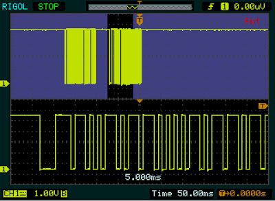
If you don't use Long Memory, you're wasting most of the capacity of the oscilloscope. Long Memory stores 64 times as much data, so you can really zoom in on the waveform. To enable Long Memory, push the Acquire menu button, then select MemDepth to set Long Mem. There's additional documentation here.

The Long Memory depth option of the Rigol DS1052E oscilloscope.

The Long Memory depth option of the Rigol DS1052E oscilloscope.

Use zoom

Once you've recorded a waveform, you can pan across it using the horizontal position knob - the waveform window indicator at the very top of the screen shows where you are. In mid-range settings, however, the pan range is fairly limited (about a factor of 5) compared to how deep you can zoom with the horizontal scale knob (about a factor of 1000 with Long Memory). Note: zoom works best with Single triggering; if you use Auto or Norm triggering and hit Run/Stop, sometimes the detailed data isn't in memory and zoom doesn't show more than is on the display.

Pushing the horizontal scale knob turns on the cool zoom mode, which lets you see the trace and a zoomed-in version at the same time, letting you zoom and pan.

The zoom feature of the Rigol DS1052E oscilloscope.

The zoom feature of the Rigol DS1052E oscilloscope.

Using the menus

Most of the menu buttons are in the group of 6 at the top. However, there's also a trigger menu button under the trigger knob and a time base menu under the horizontal position knob. This is in addition to the four vertical menu buttons: CH1, CH2, MATH, and REF. Among other things, the time base menu lets you select X-Y mode.

The menus hide about 1/6 of the display, so close the menu when you're done: push the round Menu On/Off button or push a menu button a second time.

Don't press Auto

The Auto button is right next to the Run/Stop button, so you might think it will set the trigger to Auto Sweep. Instead this button sets the controls to seemingly-random values to aotomatically display your traces. This is good if you're totally lost, but more likely to wipe out the settings you want.

Screenshots

Some oscilloscopes make screenshots easy, but the Rigol is more complicated. To take a screenshot on the Rigol, plug a USB drive into the front panel, then hit the Storage menu button, select Bit map under Storage, select External, New File, and Save. This will save NewFile0.bmp to your flash drive. (It's much easier to rename the file on your computer than on the oscilloscope.)

An alternative is to run the slightly clunky UltraScope software on your computer, which gives you access to the oscilloscope via USB. You can download "UltraScope for DS1000E" from the Rigol Software Applications page; although it has a PDF icon, it's actually a Zip file with the software.

Built-in help

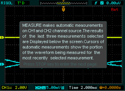
If you hold down a button or knob for three seconds, the oscilloscope displays a help screen explaining its action. (I was surprised when I discovered this by accident.)

The built-in help feature of the Rigol DS1052E oscilloscope is triggered by holding down a button or knob.

The built-in help feature of the Rigol DS1052E oscilloscope is triggered by holding down a button or knob.

Triggering

The three trigger sweep modes are Auto, Normal, and Single. Auto will keep displaying traces until you hit Run/Stop. Normal will display a trace every time the trigger condition is satisfied. Single will display a single trace when triggered and then stop. Auto is the way to see a waveform without worrying about triggering. But if you want a nice, stable waveform, set up the trigger and use Normal. Also make sure you're triggering from the right channel - the oscilloscope likes to default to using Channel 2 as the trigger.

Controlling the channels

If you've used an oscilloscope with separate controls for each channel, you may expect the knobs near CH1 to control channel 1, and the knobs near CH2 to control channel 2. Instead, if you hit CH1, the knobs control channel 1's scale and position, while if you hit CH2, Math, or Ref, the same knobs control that channel's scale and position. Make sure you're controlling the trace you think you're controlling.

Use the colored probe rings

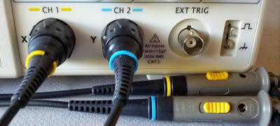
Maybe this is too obvious to mention, but putting matching colored rings on both ends of the oscilloscope probes lets you easily tell which probe goes with which channel.

Label oscilloscope probes with colored rings that match the trace colors.

Label oscilloscope probes with colored rings that match the trace colors.

Cursors

The cursors are very handy to measure voltages, times between two points, frequency, etc. (The Measure mode provides lots of automated measurements, but often doesn't measure what you want.) Manual mode lets you position two cursors (either vertical or horizontal), and the positions and difference are displayed. Track lets you position a cursor along the waveform, and a voltage cursor automatically tracks the waveform. Both time and voltage values are displayed. Auto mode is the mode you should use with Measure, in order to see what the measurements mean.

A tracking cursor puts X-Y lines on the waveform and gives measurements.

A tracking cursor puts X-Y lines on the waveform and gives measurements.

Finding the manual

Search for DS1000E (not DS1052E) to find the user's guide and other documentation.

Conclusions

I'm glad I bought the Rigol DS1052E - it performs very well for a low-price ($329) oscilloscope. (If money is no object, there's Agilent's $439,000 Infiniium oscilloscope. :-) I hope you find these tips useful. If you have any additional oscilloscope tips, please leave a comment.