Showing posts with label fractals. Show all posts

Improvements to the Xerox Alto Mandelbrot drop runtime from 1 hour to 9 minutes

Last week I wrote a Mandelbrot set program for the Xerox Alto, which took an hour to generate the fractal. The point of this project was to learn how to use the Alto's bitmapped display, not make the fastest Mandelbrot set, so I wasn't concerned that this 1970s computer took so long to run. Even so, readers had detailed suggestions form performance improvements, so I figured I should test out these ideas. The results were much better than I expected, dropping the execution time from 1 hour to 9 minutes.

The Mandelbrot set, generated by a Xerox Alto computer.

The Mandelbrot set, generated by a Xerox Alto computer.

The Alto was a revolutionary computer designed at Xerox PARC in 1973 to investigate personal computing. It introduced high-resolution bitmapped displays, the GUI, Ethernet and laser printers to the world, among other things. For my program I used BCPL, the primary Alto programming language and a precursor to C. In the photo above, the Alto computer is in the lower cabinet. The black box is the 2.5 megabyte disk drive. The Alto's unusual portrait display and an early optical mouse are on top.

Easy optimization: mirror the Mandelbrot set

The Mandelbrot set is a famous fractal, generated by a simple algorithm. Each point on the plane represents a complex number c. You repeatedly iterate the complex function f(z) = z^2 + c. If the value diverges to infinity, the point is outside the set. Otherwise, the point is inside the set and the pixel is set to black.

Since the Mandelbrot set is symmetrical around the X axis, a simple optimization is to draw both halves at the same time, cutting the time in half. (This only helps if you're drawing the whole set; this doesn't help if you're zoomed in.) I implemented this, cutting the time down to about 30 minutes. The image below shows the mirrored appearance midway through computation.

Drawing both halves of the Mandelbrot set simultaneously doubles the performance.

Drawing both halves of the Mandelbrot set simultaneously doubles the performance.

Improving the code

Embedded programmer Julian Skidmore had detailed comments on how to speed up my original code. I tried his changes and the time dropped from 30 to 24 minutes. Some of his changes were straightforward - calculating the pixel address in memory incrementally instead of using multiplication, and simplifying the loop counting. But one of his changes illustrates how primitive the Alto's instruction set is.

Quick background: my Mandelbrot program is implemented in BCPL, a programming language that was a precursor to C. The program is compiled to Nova machine code, the instruction set used by the popular Data General Nova 16-bit minicomputer. The Alto implements the Nova instruction set through microcode.

Since the Xerox Alto doesn't support floating point, I used 16-bit fixed point arithmetic: 4 bits to the left of the decimal point and 12 bits to the right. After multiplying two fixed point numbers with integer multiplication, the 32-bit result must be divided by 2^12 to restore the decimal point location. Usually if you're dividing by a power of 2, it's faster to do a bit shift. That's what I originally did, in the code below. (In BCPL, % is the OR operation, not modulo. ! is array indexing.)

let x2sp = (x2!0 lshift 4) % (x2!1 rshift 12)

Unfortunately this turns out to be inefficient for a couple reasons. Modern processors usually have a barrel shifter, so you can efficiently shift a word by as many bits as you want. The Alto's instruction set, however, only shifts by one bit. So to right shift by 12 bits, the compiled code calls an assembly subroutine (RSH) that does 12 separate shift instructions, much slower than the single instruction I expected. The second problem is the instruction set (surprisingly) doesn't have a bitwise-OR instruction, so the OR operation is implemented in another subroutine (IOR).1 I took Julz's suggestion and used the MulDiv assembly-language function to multiply two numbers and divide by 4096 instead of shifting. It's still not fast (since the Alto doesn't have hardware multiply and divide), but at least it reduces the number of instructions executed.

Shutting off the display

One way to speed up the Alto is to shut off the display.2 I tried this and improved the time from 24 minutes to 9 minutes, a remarkable improvement. Why does turning off the display make such a big difference?

One of the unusual design features of the Alto is that it performed many tasks in software that are usually performed in hardware, giving the Alto more flexibility. (As Alan Kay put it, "Hardware is just software crystallized early.") For instance, the CPU is responsible for copying data between memory and the disk or Ethernet interface. The CPU also periodically scans memory to refresh the dynamic RAM. These tasks are implemented in microcode, and the hardware switches between tasks as necessary, preempting low priority tasks to perform higher-priority tasks. Executing a user program has the lowest priority and runs only when there's nothing more important to be done.

All this task management was done in hardware, not by the operating system. The Xerox Alto doesn't use a microprocessor chip, but instead has a CPU built out of three boards of simple TTL chips. The board below shows one of the CPU boards, the control board that implements the microcode tasks and controls what the CPU is doing. It has PROMs to hold the microcode, 64-bit RAM chips (yes, just 64 bits) to remember what each task is doing, and more chips to determine which task has the highest priority.

Control board for the Xerox Alto. Part of the CPU, this board holds microcode and handles microcode tasks.

Control board for the Xerox Alto. Part of the CPU, this board holds microcode and handles microcode tasks.

The task that affects the Mandelbrot program is the display task: to display pixels on the screen, the CPU must move the pixels for each scan line from RAM to the display board, 30 times a second, over and over. During this time, the CPU can't run any program instructions, so there's a large performance impact just from displaying pixels on the screen. Thus, not using the display causes the program to run much, much faster. I still set the Mandelbrot pixels in memory though, so when the program is done, I update the display pointer causing the set to immediately appear on the display. Thus, the Mandelbrot set still appears on screen; you just don't see it as it gets drawn.

Microcode: the final frontier

The hardest way to optimize performance on the Alto is to write your own microcode. The Alto includes special microcode RAM, letting you extend the instruction set with new instructions. This feature was used by programs that required optimized graphics such as the Bravo text editor and the Draw program. Games such as Missile Command and Pinball also used microcode for better performance. Writing the Mandelbrot set code in microcode would undoubtedly improve performance. However, Alto microcode is pretty crazy, so I'm not going to try a microcode Mandelbrot.

Conclusion

After writing a Mandelbrot program for the Xerox Alto, I received many suggestions for performance improvements. By implementing these suggestions, the time to generate the Mandelbrot set dropped from one hour to 9 minutes, a remarkable speedup. The biggest speedup came from turning off the display during computation; just putting static pixels on the screen uses up a huge amount of the processing power. My improved Mandelbrot code is on github.

My goal with the Mandelbrot was to learn how to use the Alto's high-resolution display from a BCPL program. Using what I learned with the Mandelbrot, I wrote a program to display images; an example is below.3

The Xerox Alto displaying an image of the Xerox Alto displaying...

The Xerox Alto displaying an image of the Xerox Alto displaying...

Notes and references

  1. The Alto has an AND machine instruction but not an OR instruction, so the OR operation is performed by complementing an argument, ANDing, and complement-adding the complement. I.e. ab plus b. 

  2. Strictly speaking, I left the display on; it just wasn't displaying anything. The Alto uses a complex display system with a display list pointing to arbitrarily-sized blocks of pixels. (For instance, when displaying text, each block is a separate text line. Scrolling the screen just involves updating the list pointers, not moving actual data.) Thus, I could set the display list to NULL while rendering the Mandelbrot into memory. Then when the Mandelbrot was done, I simply updated the display list to make the image appear. 

  3. The recursive picture-in-picture effect is known as the Droste effect. After making this picture, I learned that generating the Droste effect on old computers is apparently a thing

One-hour Mandelbrot: Creating a fractal on the vintage Xerox Alto

I wrote a short program to generate the Mandelbrot set on the Xerox Alto, a groundbreaking minicomputer from the 1970s. The program, in the obsolete BCPL language, ran very slowly—taking almost exactly an hour—but the result below shows off the Alto's monochrome bitmapped display. (Bitmapped displays were a rarity at the time because memory was so expensive.)

The Xerox Alto took an hour to generate the Mandelbrot set.

The Xerox Alto took an hour to generate the Mandelbrot set.

The Alto was a revolutionary computer designed at Xerox PARC in 1973 to investigate personal computing. It introduced the GUI, Ethernet and laser printers to the world, among other things. In the photo above, the Alto computer itself is in the lower cabinet. The Diablo disk drive (with the 1970s orange stripe) uses a removable 14 inch disk pack that stores 2.5 megabytes of data. (A bunch of disk packs are visible behind the Alto.) The Alto's display is bitmapped with 606x808 pixels in an unusual portrait orientation, and the optical mouse is next to the display.

Last year Y Combinator received an Alto from computer visionary Alan Kay and I'm helping restore the system, along with Marc Verdiell, Luca Severini and Carl Claunch. My full set of Alto posts is here and Marc's videos are here. I haven't posted an update for a while, but now I can write new programs and download them to the Alto using the Living Computer Museum's Alto file system implementation and gateway to the Alto's 3Mb Ethernet. I decided to start with the Mandelbrot set to take advantage of the Alto's high resolution display.

Marc's latest video shows the Mandelbrot programming running on the Alto.

The Mandelbrot program

The Mandelbrot set algorithm is fairly simple. Each point on the plane represents a complex number c. You repeatedly iterate the complex function f(z) = z^2 + c. If the value diverges to infinity, the point is outside the set. Otherwise, the point is inside the set and the pixel is set to black. Setting the pixel is tricky because the Alto doesn't have a graphics API; you need to determine which bit in memory to set.4

Since the Xerox Alto doesn't support floating point1, I needed a way to represent the numbers with its 16-bit word. I use fixed point arithmetic: 4 bits to the left of the decimal point and 12 bits to the right.2 For instance, the number 1.25 is represented in 16 bits as 1.25*2^12 = 0x1400. These fixed point numbers can be added with standard integer addition. After multiplying two fixed point numbers with integer multiplication, the 32-bit result must be divided by 2^12 (i.e. shifted right by 12) to restore the decimal point location.3

The code (above) is written in BCPL, the main language used on the Alto. BCPL is a precursor to C and many features of C are clearly visible in BCPL: everything from lvalues and rvalues to the ternary operator. You can think of BCPL as C without types; the only BCPL types are 16-bit words along with C-like structs, unions and bitfields. BCPL may look unfamiliar at first, but the code above should be clear if you consider the following syntax differences with C:

  • Blocks are indicated with [ and ] instead of { and }.
  • Indexing is with a!1 instead of a[1].
  • And, Or, and Shift bit operations are &, %, and lshift/rshift.
  • Variable definitions use let.
  • Arrays are defined with vec.

More information on BCPL is in the BCPL Reference Manual and my earlier article on using BCPL with the Alto.

The Xerox Alto, a few minutes into generation of the Mandelbrot set.

The Xerox Alto, a few minutes into generation of the Mandelbrot set.

Why is the Alto so slow?

Running the Mandelbrot set illustrates the amazing improvement in computer speed since the Alto was created in 1973 and the huge changes in computer architecture. On a modern computer, a Javascript program can generate the Mandelbrot set in a fraction of a second, while the Alto took an hour. The first factor is the Alto's slow clock speed of 5.88 MHz, hundreds of times slower than a modern processor. In addition, the Alto doesn't execute machine instructions directly, but uses a relatively inefficient microcode emulator that takes many cycles to perform one machine instruction.

The ALU board from the Xerox Alto. The Alto doesn't use a microprocessor chip, but a CPU built from three boards of integrated circuits.

The ALU board from the Xerox Alto. The Alto doesn't use a microprocessor chip, but a CPU built from three boards of integrated circuits.

Unlike modern computers, the Alto doesn't use a microprocessor chip, but instead has a CPU built from three boards full of simple TTL chips. The photo above shows the arithmetic-logic unit (ALU) board, which uses four 4-bit 74181 ALU chips to perform addition, subtraction and logic operations. You can also see the CPU's registers on this board. The Alto doesn't include a hardware multiplier, but must perform multiplication by repeated shifts and adds. Thus, the Alto performs especially poorly on the Mandelbrot set, which is essentially repeated multiplications.

Conclusion

The Mandelbrot set was a quick program to try out the Alto's graphics. Next I'll try some more complex projects on the Alto. If you want to run my code, it's on Github; you can run it on the ContrAlto simulator if you don't have an Alto available.

If you're interested in retrocomputing fractals, I also generated a Mandelbrot on a 50 year old IBM 1401 mainframe The 1401 generated the Mandelbrot set in 12 minutes—not because it's a faster machine than the Alto, but because the resolution on the line printer was very very low.

Mandelbrot generated on the IBM 1401 mainframe.

Mandelbrot generated on the IBM 1401 mainframe.

Notes and references

  1. There is a floating point library (source) for the Alto. I decided not use use it since the integer Mandelbrot was already very slow. But using floating point would make sense if you wanted to zoom in on the Mandelbrot. 

  2. Fixed-point arithmetic is a common trick for fast Mandelbrot calculation. 

  3. To multiply two 16-bit numbers efficiently, I use the double precision MulFull function (written in Nova assembler) in PressML.asm, part of the Computer History Museum's archived Alto software. 

  4. The hardest part of generating the Alto Mandelbrot was figuring out how to configure the display memory and update it correctly. The details on how the display works are in chapter 4 of the Xerox Alto Hardware Manual. To summarize, the display contents are defined by a linked list of display control blocks (DCBs), which define a rectangular region of pixels on the display. A microcode task reads 16 words of pixels from memory at a time and writes them to the display board, which shifts the pixels out to the monitor. Thus, as each scanline is being written to the CRT, the CPU is busily reading the pixels for that line from memory and feeding them to the display, another reason why the Alto is slow.

    The Alto's Smalltalk environment has a simple graphics API, but we don't have Smalltalk running yet. 

12-minute Mandelbrot: fractals on a 50 year old IBM 1401 mainframe

When I found out that the Computer History Museum has a working IBM 1401 computer[1], I wondered if it could generate the Mandelbrot fractal. I wrote a fractal program in assembly language and the computer chugged away for 12 minutes to create the Mandelbrot image on its line printer. In the process I learned a bunch of interesting things about the IBM 1401, which I discuss in this article.
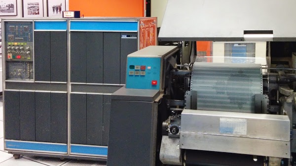
The IBM 1401 at the Computer History Museum printing the Mandelbrot fractal on the 1403 printer.

The IBM 1401 mainframe computer (left) at the Computer History Museum printing the Mandelbrot fractal on the 1403 printer (right). Note: this is a line printer, not a dot matrix printer.

The IBM 1401 computer was announced in 1959, and went on to become the best-selling computer of the mid-1960s, with more than 10,000 systems in use. The 1401 leased for $2500 a month[2] (about $20,000 in current dollars), a low price that let many more companies use computers. Even a medium-sized business could use the 1401 for payroll, accounting, inventory, order processing, invoicing, analysis, and many other tasks. The 1401 was called the Model-T of the computer industry due to its low price and great popularity.[3] Even for its time, IBM 1401 only had moderate performance, especially compared to a high-end business computer like the IBM 7080 (rental fee: $48,000 a month).[2] But the IBM 1401 became hugely popular because of its affordability, reliability, ease of use, high-quality printer and stylish appearance[4].

The 1401 was an early all-transistorized computer. These weren't silicon transistors, though, they were germanium transistors, the technology before silicon. The transistors and other components were mounted on circuit boards about the size of a playing card. These boards were called Standard Modular System (SMS) boards and each one provided a function such as a flip flop or simple logic functions. The IBM 1401 could contain thousands of SMS cards, depending on the features installed - the basic system had about 933 cards[5], while the system I used has 2881 SMS cards. (For more information on SMS cards, see my earlier article.)
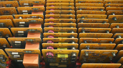
SMS cards inside the IBM 1401. These cards are part of the tape drive control, amplifying signals read from tape.

SMS cards inside the IBM 1401. These cards are part of the tape drive control, amplifying signals read from tape.

The SMS cards plug into racks (which IBM confusingly calls "gates"), that fold out from the computer as shown below. The 1401 is designed for easy maintenance - to access a gate, you just grab the handle and it swings out from the computer, exposing the wires and boards for maintenance. At the bottom of the gate, wiring harnesses connect the gate to other parts of the computer.[6] There are 24 of these gates in total.
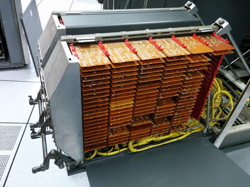
The IBM 1401 computer is built from thousands of SMS circuit cards. This open rack (called a gate) shows about 150 SMS cards.

The IBM 1401 computer is built from thousands of SMS circuit cards. This open rack (called a gate) shows about 150 SMS cards.

Unusual features of the IBM 1401

It's interesting to look at old computers because they do things very differently. Some of the unusual features of the IBM 1401 are that it used decimal arithmetic and 6-bit characters, it had arbitrary-length words, and additional instructions were available for a rental fee.

The IBM 1401 is based on decimal arithmetic, not binary. Of course it uses 0's and 1's internally, but numbers are stored as digits using binary coded decimal (BCD). The number 123 is stored as three characters: '1', '2', and '3'. If you add 7 and 8, you get the digit 1 and the digit 5. Addresses are in decimal, so storage is in multiples of 1000, not 1024: the system with 16K of memory stores exactly 16,000 characters. All arithmetic is done in base-10. So if you divide two numbers, the IBM 1401 does base-10 long division, in hardware.

The IBM 1401 does not use bytes.[9] Instead, it uses 6-bit BCD storage. Every character is stored as a 4-bit BCD digit with two extra bits called "zone bits", named A and B.[7] The two extra zone bits allow upper-case letters (and a few special symbols) to be stored, as well as digits.[8] Using a byte as the unit of operation didn't become popular until later with the IBM System/360; in the early 1960s, computers often used strange word sizes such as 13, 17, 19, 22, 26, 33, 37, 41, 45, and 50 bit words.[9]

The photo below shows the core memory module from the IBM 1401, with 4,000 characters of memory. Each bit is stored in a tiny donut-shaped ferrite core with wires running through it. The core module is more complex than you'd expect, with 16 layers (frames) in total. Eight frames hold the 6 bits of data, plus the word mark bits (explained below) and parity bits. Six frames hold data from the card reader brushes and the print hammers, for data and error checking.[10] The remaining two frames are just used for wiring.
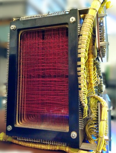
The 4000 character core memory module from the IBM 1401 computer.

The 4000 character core memory module from the IBM 1401 computer requires a huge amount of wiring.

Probably the most unusual feature of the 1401 is that it uses variable-length words, with word marks indicating each word. You might expect that variable-length words would let you use words of perhaps 8, 16, and 32 bits. But the IBM 1401 permitted words of arbitrarily many characters, up to the total size of memory! For instance, an instruction could move a 47-character string, or add 11-digit numbers. (Personally, I think it's easier to think of it as variable-length fields, rather than variable-length words.)

The word mark itself is a bit that is set on a memory location to indicate the boundary of a word (i.e. field).[11] An instruction on the IBM 1401 processes data through memory sequentially until it hits a word mark. It's important to remember that word marks are not part of the characters, but more like metadata, so they remain as new data records are read in and processed.[11] The main motivation behind variable-length words was to save expensive core memory, since each field length can be fit to the exact size required.

Another interesting thing about the IBM 1401 is that many instructions were extra-price options. The "advanced programming" feature provided new instructions for moving records, storing registers, and using index registers; this required the installation of 105 new SMS cards and (coincidentally) cost $105 a month. Even the comparison instruction cost extra. Because the 1401 uses BCD, you can't just subtract two characters to compare them as you would on most processors. Instead, the 1401 uses a bunch of additional circuitry for comparison, about 37 SMS cards for which you pay $75 a month.[12] Renting the printer buffer feature for $375 a month added a separate core storage module, 267 more SMS cards, and two new instructions. The bit test instruction cost only $20 a month and additional card punch control instructions were $25 a month. If you bought one of these features, an IBM engineer would install the new cards and move some wires on the backplane to enable the feature. The wire-wrapped backplanes made it relatively easy to update the wiring in the field.

The 1401 could be expanded up to 16,000 characters of core memory storage: 4,000 characters in the 1401 itself, and 12,000 characters in a 1406 expansion box, about the size of a dishwasher. The 12K expansion sold for $55,100 (about $4.60 per character), or rented for $1,575 a month. (You can see why using memory efficiently was important.) Along with the expanded memory came additional instructions to manipulate the larger addresses.

The tiny magnetic cores providing storage inside the IBM 1401's 4,000 character memory.

The tiny magnetic cores providing storage inside the IBM 1401's 4,000 character memory. Wires pass through each core to read and write memory. You can see multiple layers of cores in this photo.

One feature that you'd expect a computer to have is a subroutine call instruction and a stack. This is something the 1401 didn't have. To call a subroutine on the IBM 1401, you jump to the start of the subroutine. The subroutine then stores the return address into a jump instruction at the end, actually modifying the code, so at the end of the subroutine it jumps back to the caller.[13] If you want recursion, you're on your own.

Some advanced features of the 1401

Compared to modern computers, the IBM 1401 is extremely slow and limited. But it's not as primitive as you might expect and it has several surprisingly advanced features.

One complex feature of the IBM 1401 is Editing, which is kind of like printf implemented in hardware. The Edit instruction takes a number such as 00123456789 and a format string. The computer removes leading zeros and inserts commas as needed, producing an output such as 1,234,567.89. With the optional Expanded Editing feature (just $20/month more), you can obtain floating asterisks (******1,234.56) or a floating dollar sign ($1,234.56), which is convenient for printing checks. Keep in mind that this formatting is not done with a subroutine; it is implemented entirely in hardware, with the formatting applied by discrete transistors.

Another advanced feature of the IBM 1401 is extensive checking for errors. With tens of thousands of components on thousands of boards, many things can go wrong. The 1401 catches malfunctions so they don't cause a catastrophe (such as printing million dollar payroll checks). First, the memory, internal data paths, instruction decode, and BCD conversion are all protected by parity and validity checks. The ALU uses qui-binary addition to detect arithmetic errors. The card reader reads each card twice and compares the results.[10] The 1401 verifies the printer's operation on each line. (The read, punch, and print checks use the additional core memory planes discussed earlier.) As a result, the 1401 turned out to be remarkably reliable.

Because the IBM 1401 has variable word length, it can perform arbitrary-precision arithmetic. For instance, it can multiply or divide thousand-digit numbers with a single instruction. Try doing that on your Intel processor! (I tried multiplying 1000-digit numbers on the 1401; it takes just under a minute.) Hardware multiply/divide is another extra-cost feature; to meet the 1401's price target, they made it an option with the relatively steep price of $325 per month. You do get a lot of circuitry for that price, though - about 246 additional SMS cards installed in two gates.[14] And remember, this is decimal multiplication and division, which is much more difficult to do in hardware than binary.

The 1401 I used is the Sterling model which it supports arithmetic on pounds/shillings/pence, which is a surprising thing to see implemented in hardware. (Up until 1971, British currency was expressed in pounds, shillings, and pence, with 12 pence in a shilling and 20 shillings in a pound. This makes even addition complicated, as tourists often discovered.) By supporting currency arithmetic in hardware, the 1401 made code faster and simpler.[15]
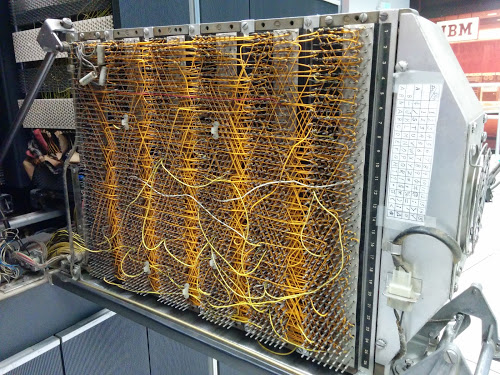
A maze of wire-wrapped wires connects the circuits of the IBM 1401 computer.

A maze of wire-wrapped wires on the back of a gate connects the circuits of the IBM 1401 computer. The wiring was installed by automated machinery, but the wiring could be modified by field engineers as needed.

Implementing the Mandelbrot in 1401 assembly language

Writing the Mandelbrot set code on the 1401 is a bit tricky since I did it in assembly language (called Autocoder). The hardest part was thinking about word marks. Another complication was the 1401 doesn't have native floating point arithmetic, so I used fixed point: I scaled each number by 10000, so I could represent 4 decimal places with an integer. The 1401 is designed for business applications, not scientific applications, so it's not well-suited for fractal generation. But it still got the job done.

The 1401 didn't need to be programmed in assembly language - it supports languages such as Fortran and COBOL - but I wanted the full 1401 experience. It does amaze me though that you can run a COBOL compiler on a machine with just 4,000 characters of memory. The Fortran compiler required a machine with 8,000 memory location; in order to fit, it ran in 63 separate phases.

The assembly language code for the Mandelbrot fractal is shown below. The first part of the code defines constants and variables with DCW. This is followed by three nested loops to loop over each row, each column, and the iterations for each pixel. Some of the instructions in the code are M (multiply), A (add), S (subtract), and C (compare). Comments start with asterisks.

               JOB  MANDELBROT
     *GENERATES A MANDELBROT SET ON THE 1401
     *KEN SHIRRIFF  HTTP://RIGHTO.COM
               CTL  6641
               ORG  087
     X1        DCW  001  *INDEX 1, COL COUNTER TO STORE PIXEL ON LINE
               ORG  333
     *
     *VALUES ARE FIXED POINT, I.E. SCALED BY 10000
     *Y RANGE (-1, 1). 60 LINES YIELDS INC OF 2/60*10000
     *
     YINC      DCW  333
     XINC      DCW  220          *STEP X BY .0220
     *
     *Y START IS -1, MOVED TO -333*30 FOR SYMMETRY
     *
     Y0        DCW  -09990       *PIXEL Y COORDINATE
     *
     *X START IS -2.5
     *
     X0INIT    DCW  -22000       *LEFT HAND X COORDINATE
     X0        DCW  00000        *PIXEL X COORDINATE
     ONE       DCW  001
     ZR        DCW  00000        *REAL PART OF Z
     ZI        DCW  00000        *IMAGINARY PART OF Z
     ZR2       DCW  00000000000  *ZR^2
     ZI2       DCW  00000000000  *ZI^2
     ZRZI      DCW  00000000000  *2 *ZR *ZI
     ZMAG      DCW  00000000000  *MAGNITUDE OF Z: ZR^2 + ZI^2
     TOOBIG    DCW  00400000000  *4 (SCALED BY 10000 TWICE)
     I         DCW  00           *ITERATION LOOP COUNTER
     ROW       DCW  01
     ROWS      DCW  60
     COLS      DCW  132
     MAX       DCW  24           *MAXIMUM NUMBER OF ITERATIONS
     *
     *ROW LOOP
     *X1 = 1  (COLUMN INDEX)
     *X0 = -2.2 (X COORDINATE)
     *
     START     LCA  ONE, X1     *ROW LOOP: INIT COL COUNT
               LCA  X0INIT, X0  *X0 = X0INIT
               CS   332         *CLEAR PRINT LINE
               CS               *CHAIN INSTRUCTION
     *
     *COLUMN LOOP
     *
     COLLP     LCA  @00@, I     *I = 0
               MCW  X0, ZR      *ZR = X0
               MCW  Y0, ZI      *ZI = Y0
     *
     *INNER LOOP:
     *ZR2 = ZR^2
     *ZI2 = ZI^2
     *IF ZR2+ZI2 > 4: BREAK
     *ZI = 2*ZR*ZI + Y0
     *ZR = ZR2 - ZI2 + X0
     *
     INLP      MCW  ZR, ZR2-6   *ZR2 =  ZR
               M    ZR, ZR2     *ZR2 *= ZR
               MCW  ZI, ZI2-6   *ZI2 =  ZI
               M    ZI, ZI2     *ZI2 *= ZI
               MCW  ZR2, ZMAG   *ZMAG = ZR^2
               A    ZI2, ZMAG   *ZMAG += ZI^2
               C    TOOBIG, ZMAG  *IF ZMAZ > 4: BREAK
               BH   BREAK
               MCW  ZI, ZRZI-6  *ZRZI = ZI
               M    ZR, ZRZI    *ZRZI = ZI*ZR
               A    ZRZI, ZRZI  *ZRZI = 2*ZI*ZR
               MCW  ZRZI-4, ZI  *ZI = ZRZI (/10000)
               MZ   ZRZI, ZI    *TRANSFER SIGN
               A    Y0, ZI      *ZI += Y0
               S    ZI2, ZR2    *ZR2 -= ZI2
               MCW  ZR2-4, ZR   *ZR = ZR2 (/10000)
               MZ   ZR2, ZR     *TRANSFER SIGN
               A    X0, ZR      *ZR += X0
     *
     *IF I++ != MAX: GOTO INLP
     *
               A    ONE, I      *I++
               C    MAX, I      *IF I != MAX THEN LOOP
               BU   INLP
               MCW  @X@, 200&X1  *STORE AN X INTO THE PRINT LINE
     BREAK     C    X1, COLS    *COL LOOP CONDITION
               A    ONE, X1
               A    XINC, X0    *X0 += 0.0227
               BU   COLLP
               W                *WRITE LINE
     *
     *Y0 += YINC
     *IF ROW++ != ROWS: GOTO ROWLP
     *
               C    ROW, ROWS   *ROW LOOP CONDITION
               A    ONE, ROW
               A    YINC, Y0    *Y0 += 0.0333
               BU   START
     FINIS     H    FINIS       HALT LOOP
               END  START

I compiled and ran the code with the ROPE compiler and simulator before using the real computer.[16] The cards were punched automatically by an IBM 029 keypunch controlled by a PC through a bunch of USB-controlled relays. The photo below shows the keypunch in operation. Each blank card drops down from the feeder in the upper right. The card is punched as it moves to the left. Punched cards are then flipped up and stacked in the upper left area (empty in this picture).
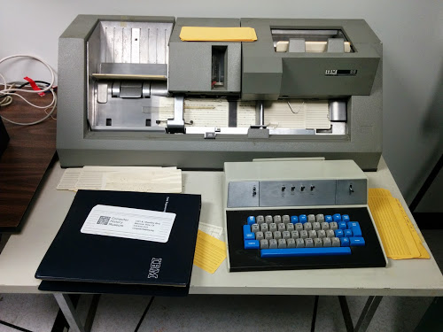
An IBM 029 keypunch preparing a card deck that generates the Mandelbrot fractal.

An IBM 029 keypunch preparing a card deck that generates the Mandelbrot fractal.

The resulting card deck is shown below, along with the output of execution. The program fits onto just 16 cards, but the card format is a bit unusual. The machine code for the Mandelbrot program is punched into the left half of the each card, with code such as M384417A395417. An interesting thing about the 1401 is the machine code is almost human-readable. M384417 means Move field from address 384 to address 417. A395417 means Add the number at address 395 to the number at address 417. The text on these cards is the actual machine code that gets executed, not the assembly code. Since the machine is character-based, not binary, there's no difference between the characters "428" and the address 428.
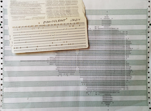
The card deck to generate the Mandelbrot fractal on the IBM 1401 computer.

The card deck to generate the Mandelbrot fractal on the IBM 1401 computer, along with the output. The white stripe through the fractal near the right is where a hammer in the printer malfunctioned.

If you look at the right half of the cards, there's something totally different going on, with text like L033540,515522,5259534. There's no operating system, so, incredibly, each card has code to copy its contents into the right place in memory (L instruction), add the word marks (, instruction), and load the next card. In other words, the right hand side of each card is a program that runs card-by-card to load into memory the program on the left hand side of the card deck, which is executed after the last card is loaded.[17]

To run the program, first you hit the "Power On" button on the IBM 1401 console. Relays clunk for a moment to power up the system and then the computer is ready to go (unlike modern computers that take so long to boot). You put the cards into the card reader and hit the "Load" button. The cards fly through the reader at the remarkable speed of 800 cards per minute so the Mandelbrot program loads in just over a second. The console starts flickering as the program runs, and every few seconds the line printer hammers out another line of the fractal. After 12 minutes of execution, the fractal is done. (Interestingly enough, the very first picture of a Mandelbrot set was printed on a line printer in 1978.[18])
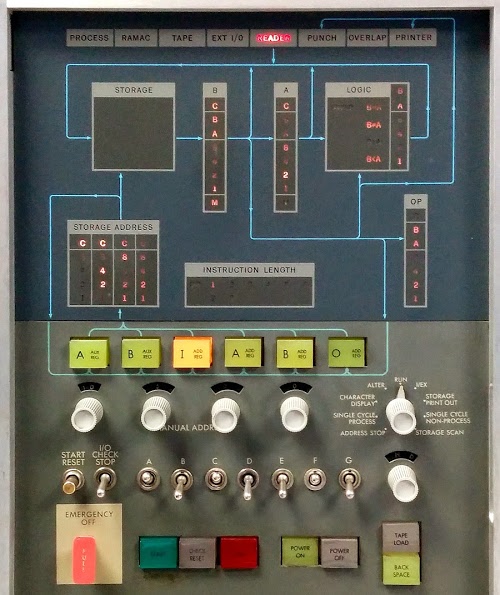
The console of an IBM 1401 mainframe.

The console of the IBM 1401 mainframe. The top half shows the data flow through the computer, from storage to the B and A registers and the logic unit. Each 6-bit value is displayed as 1248ABC, where A and B are zone bits and C is the check (parity) bit. On the right, "OP" shows the operation being executed. Below are knobs to manually access memory. On the left, the "Start Reset" button clears an error, such as the card read failures I would hit. At the bottom are the important buttons to turn the computer on and off. Note the Emergency Off handle that immediately cuts the power.

Conclusions

Writing a Mandelbrot program for the IBM 1401 was an interesting project. You think a bit differently about programming when using decimal numbers and keeping track of word marks. But I have to say that comparing the performance with a current machine - not to mention the storage capacity - makes me appreciate Moore's Law.

The Computer History Museum in Mountain View runs demonstrations of the IBM 1401 on Wednesdays and Saturdays. It's amazing that the restoration team was able to get this piece of history working, so if you're in the area you should definitely check it out. The schedule is here. Tell the guys running the demo that you heard about it from me and maybe they'll run my prime number program or Pi program. You probably wouldn't want to wait for the Mandelbrot to run.

Thanks to the Computer History Museum and the members of the 1401 restoration team, Robert Garner, Ed Thelen, Van Snyder, and especially Stan Paddock. The 1401 team's website (ibm-1401.info) has a ton of interesting information about the 1401 and its restoration.

Notes and references

[1] The Computer History Museum has two working 1401 computers: the "German 1401" and the "Connecticut 1401" (based on where they came from). I used the German 1401 since the Connecticut 1401 was undergoing card reader maintenance at the time.

[2] While the $2500 per month rental rate is quoted in many places, the price could climb to $10,000 a month for a full system with multiple tape drives. The price varied greatly depending on the 1401 model, the amount of memory, and the peripherals (tape drives, card reader, printer, disk drive). The minimal configuration (1401 Model A, 1402 card reader, and 1403 printer) went for $2,475 a month (or purchased for $125,600 - about $1 million accounting for inflation). A "recommended" configuration with 8K of memory, processor options, and another printer went for $4,610 a month. Tape drives boosted the price at $980 a month for the interface and $1100 a month for each 729 IV tape drive. A 4000 character memory expansion cost $575 per month.

Detailed information on 1961 computers including rental rates is available in an interesting survey of computers in 1961, the thousand-page A Third Survey of Domestic Electronic Digital Computing Systems", Report No. 1115, March 1961 (1401 page). The basic IBM rental price was for one 8-hour shift (176 hours a month). The computers included a time counter, and users were billed extra if they went over the allotted time. Customers often paid a higher rental fee so they could run 24/7.

[3] The comment that the 1401 became the Model-T of the computer industry is from the article IBM System/360, by IBM VP Bob Evans. One piece of trivia from that article is the IBM 1620 rented for $1600 a month, making it the first IBM system renting for a price less than its model number.

[4] The IBM 1401 has a very distinctive style, especially compared to earlier IBM computers (such as the 650 or 704) with a very utilitarian, industrial appearance. The sleek, modernist style of the 1401 isn't arbitrary, but the result of a detailed industrial design process. The book The Interface: IBM and the Transformation of Corporate Design has a very interesting discussion of the effort IBM put into industrial design. Edgar Kaufmann, Jr came up with important design ideas that were developed by Eliot Noyes. Some design concepts were recessed pedestals for a feeling of floating and lightness, the concealment of most of the circuitry, expressing the "inherent drama" of computers, the carefully controlled color scheme, and modern materials for the cabinets. The tape drives in particular were wildly successful at expressing the "inherent drama" of computing, to the point that spinning tape drives became a movie cliche (tvtropes: Computer Equals Tapedrive).

[5] The number of SMS cards in an IBM 1401 depends on the model, the options installed, engineering changes (i.e. fixes) applied to the system, and the amount of memory in use. I got the number 1206 by analyzing the SMS plug chart and counting 933 basic cards, 267 Sterling basic cards, 6 power supply cards, and 11 cards for storage support. This machine is the Sterling model, so it is slightly more complex than the regular model.

[6] The IBM 1401 has 32 "potential" gates: 16 on the front and another 16 on the back, but only 24 of these are gates with circuitry. The two potential panels in the upper left are taken up by the control panel, which swings out to reveal the core memory behind it. Four panels have power supplies behind them (although much of the power supply is inside the card reader, strangely). Two more spots are occupied by the surprisingly thick cables connecting the 1401 to peripherals. This leaves 24 swing-out gates; some may be unused, depending on the optional features installed.

[7] The zone bits are closely related to the zone punches in IBM punch cards. The top row of a punch card is the 12 (Y) zone, and the row beneath it is the 11 (X) zone. A number has one hole punched in the card row corresponding to the number (rows 0 through 9). A character usually has two holes punched: 1 through 9 for the BCD value, and a zone punch for the zone bits. The zone punch is card zone 11 for zone bit B set, card zone 12 for zone bits A and B, or card row 0 for zone bit A.

There are a few complications, though, that mess up this pattern. First, for characters outside the 0-9 range, two digit punches are used: 8 and the digit for the low three bits. (e.g. '#' is stored as bits 8, 2, and 1, so it is punched as 8 and 3.) Second, because card row 0 is used both for the digit 0 and as a zone punch, there is a conflict and the value 0 is treated as 10 in certain conditions (and punched as 8 and 2). Because a blank has no punches and is stored as 0 internally, the digit 0 is stored as 10. Different IBM systems treat these corner cases differently. Custom features were available for the 1401 to provide compatibility as needed.

[8] The zone bits are used for a few things in addition to letters. A zone bit is added to the low-order digit of a number to indicate the sign of the number. Memory addresses are expressed as three digits, which would allow access to 1000 locations; by using zone bits, the three digit address can reach 16,000 locations. The zone bits also track overflow in arithmetic operations.

[9] Originally byte referred to the group of bits used to encode a character, even if it wasn't 8 bits (see Planning a Computer System: Project Stretch, p40). Some examples of unusual word lengths: The RCA 601 supported 6, 8, 12, 16-bit, or variable-length words. SPEC used 13-bit words. The Hughes Airborne Computer used 17-bit words, while the Hughes D Pat used 19-bit words and the Hughes M 252 used 20-bit words. The RW 300 used 18-bit words, while the RW 400 used 26-bit words. The Packard Cell 250 used 22-bit words. UNIVAC 1101 used 24-bit words. ALWAC II used 32 bits plus sign (33 bits). COMPAC used 37 bits (36 + sign). AN/MJQ used 41-bit words. SEAC used 45 bits (44 plus sign). AN/FSQ 31 used 48 bit words. ORACLE used 50-bit words. The Rice University computer used 54-bit words. Details on these computers are in A Third Survey of Domestic Electronic Digital Computing Systems.

[10] The card reader reads each card twice and verifies that the hole count is the same for both reads. If the counts don't match, the card reader detects the error and stops. In more detail, each card is read "sideways", a row of 80 positions at a time. Two bits keep the status of each column. One bit is turned on if there is any hole. The other bit is toggled for each hole. (Thus, it's not exactly a count, simplifying the logic.) The process is reversed on the second read, so both bits will end up back at 0 for a correct read.

Since the next card is already getting read as the first card is getting verified, two sets of bits are needed, one for the first card and one for the second card. Thus, four planes of 80 bits each are used in total to verify card reads.

Each of the 240 brushes in the card reader has a separate wire that goes through a specific core in the 1401's core memory. Likewise, each of the 132 print hammers in the printer is wired directly to an individual core. Thus, there are thick cables containing hundreds of wires between the IBM 1401 and the card reader and the printer.

[11] There are several details of wordmarks I'll point out. The IBM 1401 is obviously big-endian, since that's how numbers are punched on cards. Since arithmetic operations need to start with the lowest-order digit, they start at the "end" of the number and work backwards through memory to the highest-order digit. The consequence is an instruction is given the address of the end of the field and progresses to lower addresses until it hits the word mark, which is at the beginning of the field. This seems backwards if you're a C programmer, where you start at the beginning of a string and go forwards until you hit the end.

Word marks are also used to indicate the start of each instruction. Instructions can be 1 to 8 characters long, and the presence of a word mark controls the length. Bootstrapping the word marks for the first instructions loaded into the computer requires some tricks.

[12] The comparison logic is more complex than you'd expect. Surprisingly, the comparison order doesn't match the binary order of characters. Also, comparisons aren't implemented with subtraction (like most processors). Instead, logic first determines if the characters are special characters or not - special characters are before regular characters (with some exceptions: for example, - is between I and J). Then a lot of AND-OR logic performs basically brute-force comparison by looking at various bit patterns. The results of a comparison can be seen on the control panel in the Logic box. The optional compare logic is shown on the Intermediate Level Diagrams (ILD), page 37.

[13] Self-modifying code, where the program changes its own instructions, was common in the past. A guide to IBM 1401 programming, 1961, has a whole chapter (6) on this, discussing how "we are able to operate on instruction in storage just as through they were data". Treating code as data wasn't done only by Lisp programmers. In fact, the book calls the ability of a program to modify itself "by all odds the most important single feature of the stored program concept." As well as subroutine returns, IBM 1401 programmers used self-modifying code for indexing, address computation, and complex conditional branching. On current machines, Self-modifying code is rare because it's harder to debug and messes up the instruction pipeline.

[14] For details on how the multiply and divide operations work internally, see the optional feature manual. This circuit has some complicated optimizations. For example, to speed up the repeated additions, it will add the doubled value instead if appropriate. But doubling a decimal value takes a fairly complicated circuit (unlike binary doubling, which is trivial). And there's error checking to make sure nothing goes wrong in the doubling.

[15] The Sterling circuitry to support £sd math is even more complicated because shillings and pence are stored in a compressed form. The obvious representation is a two-digit field for pence (0 to 11) and a two-digit field for shillings (0 to 19). But to save precious memory and storage space, the BSI standard and incompatible IBM standard use one-digit fields and special characters. A knob on the control panel selects which standard to use. The Sterling hardware must perform arithmetic on this compressed representation, as well as handling the non-decimal bases of shillings and pence.

This knob on the control panel of the IBM 1401 computer selects the storage mode for pence and shillings.

This knob on the control panel of the IBM 1401 computer selects the storage mode for pence and shillings.

[16] If you want to write a program for the 1401, instructions on using the ROPE simulator are here. It's a simple IDE that lets you edit assembly code (which is called Autocoder), assemble it, and then run it on the simulator. Take a look at A guide to IBM 1401 Programming and Programming the 1401 if you want to understand how to program the 1401. The 1401 Reference Manual is also useful for understanding what the instructions do.

[17] Each card also has a four-digit sequence number in the last columns. This lets you re-sort the cards if you happen to drop the deck and scramble the program.

[18] The first picture of the Mandelbrot set appears in 1978 paper by Brooks and Matelski, prior to Mandelbrot's work. (Thanks to Robert Garner for pointing this out.) There's some controversy over who "really" discovered the Mandelbrot set. See Who Discovered the Mandelbrot Set? in Scientific American for a discussion.

A new multi-branch algorithm to render rational-exponent Mandelbrot fractals: Part I

If you came here from Hacker News, thanks for visiting. You might want to check out the Hacker News comment thread too.

The Mandelbrot fractal is generated by repeatedly iterating the complex function f(z) = z^2 + c, and testing if the result diverges to infinity or not. An obvious generalization is to use a different exponent in place of 2 (yielding a fractal sometimes called the Multibrot). In this article, I describe a new algorithm for fractals with a rational exponent, for example z^2.5+c. This algorithm uses all branches of the complex roots in parallel, rather than just the principal root, which displays new structure of the fractal.

Previous techniques to display fractional-exponent fractals force the multi-valued complex root to have a single value, which distorts the "true" fractal. By computing all the possible root values in parallel, I determine the "true" form of the fractal.

The following image shows the multi-branch fractal for z^2.5+c. Click on the image (or any of the other images) for a full-size version.

The multi-branch fractal for z^2.5+c.

The multi-branch fractal for z^2.5+c.

The problem with square roots

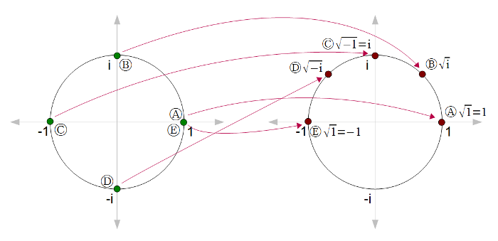
Numbers generally have two square roots, although we typically only think about the principal (positive) one. For instance (-2)2 = 22 = 4, so sqrt(4) = +2 or -2. (Zero is the exception.) Likewise, complex numbers have two square roots. Unfortunately, we can't just pick one of the square roots without running into discontinuities. For instance, suppose we start with sqrt(1) = 1. Then look at sqrt(i), sqrt(-1), and sqrt(-i) on the following diagram. The roots are nice and continuous from (A) to (D) until we end up back at (E), where sqrt(1) = -1. Something has to give; somewhere the square root function is going to become discontinuous.
Square root of complex numbers
This problem can be solved by making a branch cut, where the function is discontinuous. This cut is typically along the negative real axis, so at point (C) the square root function would jump from i to -i. Note that cutting along the negative real axis is arbitrary.

The disadvantage of making the square root function discontinuous is the resulting fractatals will have discontinuities. In addition, the appearance of the fractal will change if the arbitrary cut is made in a different location. Thus, in a sense, if you generate a fractal based on z^2.5+c, you're not seeing the real fractal, but artifacts based on arbitrary decisions.

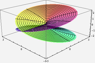
Multi-valued complex functions can be expressed as Riemann surfaces. Instead of being defined on the complex plane, the function is defined on a surface which locally looks like the complex plane, but can have more structure. For instance, the following illustration shows the Riemann surface for the complex square root. Note that for each point (except 0), there are two values for the square root.

A Riemann surface for the complex function f(z) = sqrt(z).

A Riemann surface for the complex function f(z) = sqrt(z).

ParametricPlot3D[{r * Cos[theta], r * Sin[theta], Sqrt[r] * Cos[theta/2]}, {theta, 0, 4Pi}, {r, 0, 5}, PlotPoints -> 100, PlotStyle->Opacity[.6], ViewPoint -> {-2, -2, 1}, Mesh->True, ColorFunctionScaling->False, ColorFunction -> Function[ {x,y,z,theta, r}, Hue[theta/(4Pi), .9, .9]]]

How do you compute a complex root?

In general, a complex power a^b is defined as exp(b * ln(a)), using the complex exponential and logarithm. The complex logarithm is multi-valued, which is the base of the multi-valued problems. These functions can be computed using well-known formulas.

Because I'm using square roots instead of arbitrary powers (for now), I can use a simpler complex square root formula (details at Wikipedia). The following code takes a complex number x + i * y, and returns the primary square root x1 + i * y1. Note that the negative -(x1 + i * y1) is the other square root.

public static void csqrt(double x, double y, ref double x1, ref double y1)
{
  double m = x * x + y * y;
  double r = Math.Sqrt(m);
  x1 = Math.Sqrt((r + x) / 2.0);
  if (y > 0) {
    y1 = Math.Sqrt((r - x) / 2.0);
  } else {
    y1 = -Math.Sqrt((r - x) / 2.0);
  }
}

Generating the real fractal, with all the branches

The key idea of the multi-branch algorithm is instead of forcing the square root function to have a single arbitrary value, embrace the multi-valued nature of the square root and try both values. In this way, we can see the "true" picture of the fractional-exponent Mandelbrot set. Specifically, instead of taking one value for the square root, the algorithm evaluates the fractal recursively trying each square root in turn. The two return values are combined to yield the final result.

To generate the multi-branch fractal, we can test each point to see if any branch converges. However, the result is more interesting if we count how many of the branches converge for each pixel. The result can be anywhere between all of them (in the middle of the fractal) to none of them (outside the fractal).

To decide if a point diverges, I use the standard escape-time technique of checking if the magnitude of z exceeds a bound. If z exceeds the bound, I know the point diverges. If z doesn't exceed the bound by the end of the iterations, I assume it doesn't diverge. This is not necessarily true, which is why the accuracy of a fractal increases as the number of iterations increases. I test for divergence with a bound of magnitude^2 > 4; the exact value of the bound doesn't make much difference as long as it is large enough to guarantee divergence.

The following code shows how the number of convergent branches c is computed recursively. Note that (z25x, z25y) is one of the values of z^2.5, and (-z25x, -z25y) is the other. The key to the multi-branch fractal is that both paths are explored, rather than just one. For a particular pixel, eval(x, y, x, y, 0) is called and the the result is displayed with a suitable colormap.

int eval(double zx, double zy, double cx, double cy, int n)
{
  if (n == max)
  {
    return 1;
  }
  // zsquared is z^2, zroot is sqrt(z), z25 is z^2.5
  double zsquaredx = zx * zx - zy * zy;
  double zsquaredy = 2 * zx * zy;
  double zrootx = 0, zrooty = 0;
  CMath.csqrt(zx, zy, ref zrootx, ref zrooty);
  double z25x = zsquaredx * zrootx - zsquaredy * zrooty;
  double z25y = zsquaredx * zrooty + zsquaredy * zrootx;

  int c = 0;
  // Use the first root
  double newx1 =  z25x + cx;
  double newy1 =  z25y + cy;
  if (newx1 * newx1 + newy1 * newy1 < 4)
  {
    c += eval(newx1, newy1, cx, cy, n + 1);
  }

  // Use the second root
  double newx2 = -z25x + cx;
  double newy2 = -z25y + cy;
  if (newx2 * newx2 + newy2 * newy2 < 4)
  {
    c += eval(newx2, newy2, cx, cy, n + 1);
  }
  return c;
}

The multi-branch fractal is exponentially slow compared to regular escape time fractals. At each iteration, there are two choices of square root, with the consequence that we evaluate 2^n values at each pixel, rather than n with a normal escape-time fractal. Unfortunately, this makes computation very expensive. For a regular escape-time fractal, you might use an iteration depth of hundreds for each pixel. But for the multi-branch fractal, it gets very slow if you go above about 12 iterations.

The above algorithm provides detail of the "inside" of the multi-branch fractal. Note that there is a central region where every branch converges. This isn't too surprising, since if c is sufficiently small, z^2.5 will converge with either branch. Outside this region is a complex area where points just barely converge on some branches, and flipping the branch anywhere will make the point diverge. The eight "snowflake" buds are what I find most interesting; these are regions that diverge for almost all branches, but converge for the "right" branches.

The resulting fractal is obviously symmetric when reflected in the y axis or when rotated by 60 degrees. The proofs are straightforward . In comparison, the regular z^2.5+c fractal is not rotationally symmetric because of the effect of branch cuts.

I believe the multi-branch fractal is connected (unlike the regular z^2.5+c fractal), but I don't have a proof. Interestingly, the fractal has some holes (i.e. is not simply connected). I believe these happen where different branches overlap in such a way that they happen to leave gaps, but on a particular branch (whatever that means) the fractal does not have holes.

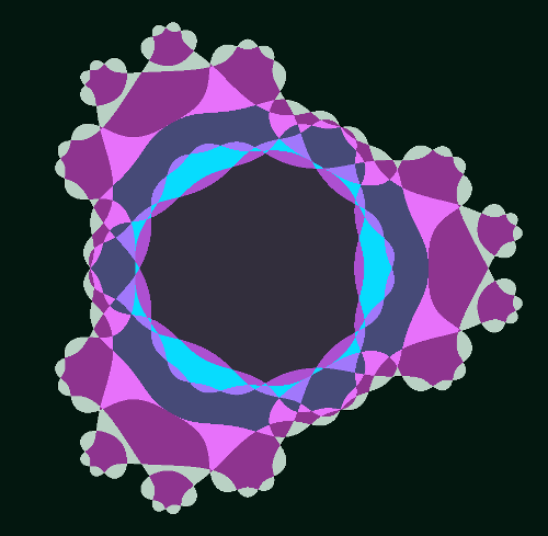
The best way to see the holes is to look at the "outside" of the fractal. Instead of counting how many branches converge, the code can be easily modified to determine the maximum number of iterations it takes for a branch to diverge. This is similar to the standard escape-time fractal algorithm with level sets approaching the fractal (except of course, it uses multiple branches). In the image below, you can see dark blue spots inside the fractal near the "snowflakes" that look like image noise. These are actually areas that are outside the fractal with complex structure.

The multi-branch fractal for z^2.5+c, showing details of the exterior.

The multi-branch fractal for z^2.5+c, showing details of the exterior.

Stepping through iteration-by-iteration

One way to understand the multi-branch fractal is to step through one iteration at a time. If we start with one iteration, there are two branches at each pixel. We see a central region that converges for both branches, and three lobes that converge only for one branch. Note that the boundary wraps around the center twice. Perhaps you can imagine this boundary on the Riemann surface at the top of the page.

The multi-branch fractal for z^2.5+c, showing the number of convergent branches after 1 iteration.

After two iterations, the structure is considerably more complex. Each point has four different branch possibilities, and can converge on 0 to 4 of the branches. The boundary now winds around 4 times on a more complex Riemann surface. Note that each boundary in the first image has split into two boundaries woven together - these are the two different branches for the second iteration.
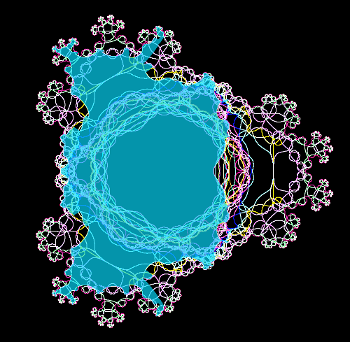
The multi-branch fractal for z^2.5+c, showing the number of convergent branches after 2 iterations.
With three iterations, the rough shape of the multi-branch fractal is starting to appear.

 The multi-branch fractal for z^2.5+c, showing the number of convergent branches after 3 iterations.

The multi-branch fractal for z^2.5+c, showing the number of convergent branches after 3 iterations.
Jumping to 14 iterations, the fractal has achieved its basic shape. Note the rough shape of the central region that converges for all branches. It is surrounded by many chaotic stripes, where most of the branches converge, but a few diverge. There are three big regions that mostly converge to two-cycles, and three smaller regions that mostly converge to three-cycles. The snowflakes, which diverge for almost all branches, are now clearly visible.

The multi-branch fractal for z^2.5+c, showing the number of convergent branches after 14 iterations.

The multi-branch fractal for z^2.5+c, showing the number of convergent branches after 14 iterations.

Snowflakes and the Monkey's Paw

The "snowflakes" are made of a repeated motif that I call the "monkey's paw". Looking at one of these regions while increaing the number of iterations helps illustrate some of the structure of the fractal. After 3 iterations, a basic four-fingered "paw" is visible.

Multi-sheet z^2.5+c fractal at (-.90, 1.14): 3 iterations

Multi-sheet z^2.5+c fractal at (-.90, 1.14): 3 iterations
After one more iteration, each finger splits into a new four-fingered paw. If you follow the edge of the paw, you'll discover a complex topology that winds through the paws in the order 2, 4, 1, 3, and winds through the fingers of each paw in the same order. This helps to illustrate the complex geometry of the underlying Riemann surface, which is splitting in the middle of each paw. (I hope to generate a 3D image to make this clearer.)

Multi-sheet z^2.5+c fractal at (-.90, 1.14): 4 iterations

Multi-sheet z^2.5+c fractal at (-.90, 1.14): 4 iterations
After another iteration, each finger sprouts another new paw, and paws are starting to bud on the arms.

Multi-sheet z^2.5+c fractal at (-.90, 1.14): 5 iterations

Multi-sheet z^2.5+c fractal at (-.90, 1.14): 5 iterations
After 6 iterations, there are paws sprouting everywhere. There is also a stable region in the middle of the original paw that converges for most of the branches.

Multi-sheet z^2.5+c fractal at (-.90, 1.14): 6 iterations

Multi-sheet z^2.5+c fractal at (-.90, 1.14): 6 iterations
Finally, jumping to 12 iterations, the paws have developed into "snowflakes", with five-fold branching (the four fingers plus the arm). The five-fold branching appears all over the fractal. In the middle of each paw is a stable rgion, which is roughly self-similar to the overall fractal. (Just like tiny Mandelbrots appear in the threads of the Mandelbrot set.)

Multi-sheet z^2.5+c fractal at (-.90, 1.14): 12 iterations

Multi-sheet z^2.5+c fractal at (-.90, 1.14): 12 iterations

Edge detection

Another way to see the structure is to filter the fractal to show the edges. This shows the structure of the boundary between convergent and divergent regions. The following image show the boundary after three iterations. If you follow the line around, you can see its complex structure.

Multi-sheet z^2.5+c fractal: edges of escape regions after 3 iterations.

Multi-sheet z^2.5+c fractal: edges of escape regions after 3 iterations.
After 5 iterations, the boundary has become very complex. Note the development of the "monkey's paws" discussed earlier. Also notice how many boundaries pass near the central region, causing the complexity there.

Multi-sheet z^2.5+c fractal: 5 iterations, edges of escape regions after 5 iterations.

Multi-sheet z^2.5+c fractal: 5 iterations, edges of escape regions after 5 iterations.

Comparison with the "regular" escape-time fractal

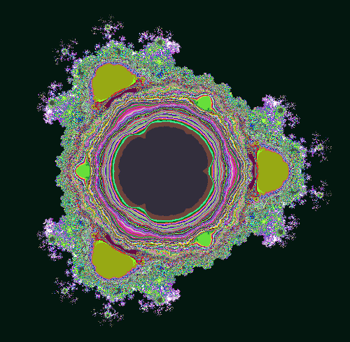
Comparing the multi-branch fractal with the single-branch fractal shows some interesting features. The image below is the fractal generated from z^2.5+c using the standard algorithm. Superficially, it looks a lot like the Mandelbrot set. However, note that it is not connected, with some unconnected islands in the upper center for example.
The regular escape-time fractal for z^2.5+c.
Zooming in on one of the "antennas" of the regular fractal illustrates more of the disconnected components. You can also see the discontinuities due to the branch cut, lines where the fractal gets cut off. There is also a somewhat self-similar region, in yellow.

Regular escape-time fractal at (-.82, 1.21)

Regular escape-time fractal at (-.82, 1.21)

Below is the same region of the fractal, displayed using the multi-branch algorithm. Note that there is much more detail provided by the multi-branch algorithm. Also note that the stable self-similar region looks very much like the overall multi-branch fractcal.

Multi-branch fractal at (-.82, 1.21)

Multi-branch fractal at (-.82, 1.21)

The regular fractal is actually a subset of the multi-branch fractal, since each computation in the single-branch fractal will be done in one of the paths of the multi-branch fractal. In the image below, the regular fractal has been overlayed on the multi-branch fractal. Note that the regular fractal exactly falls onto the multi-branch fractal, but is missing most of the branchess. Clicking on the image below will show an animation flipping between the regular fractal and the multi-branch fractal.

Overlay of regular escape-time and multi-branch fractals at (-.82, 1.21)

Overlay of regular escape-time and multi-branch fractals at (-.82, 1.21)

One surprising thing is how different the regular and multi-branch fractals look in general. The regular fractal looks much more "Mandelbrot-like" with its sequences of bulbs. I expect that the multi-branch fractal also has a similar structure, but hidden by the overlapping branches.

Another way of seeing how the fractals are related is to overlay the regular fractal with the edge map of the multi-branch fractal. In the following image, both fractals are rendered to a depth of 5 iterations. The regular fractal is displayed in cyan on top of the edges of the multi-branch fractal. Note that the edges match exactly, which is expected from the mathematics. Note also that the regular fractal jumps from curve to curve as it hits the branch cuts, rather than following a single curve. Also note how much of the multi-branch struture is missed by the regular fractal. (The regular fractal is very "blobby" because the iteration count is so low. A higher iteration could would make it too hard to see the edges.)

Multi-sheet z^2.5+c fractal: 5 iterations, edges of escape regions. Overlaid with regular z^2.5+c fractal.

Multi-sheet z^2.5+c fractal: 5 iterations, edges of escape regions. Overlaid with regular z^2.5+c fractal.

What's next?

There are many more things to explore with multi-branch fractals. The techniques can easily be extended to values other than 2.5. Rendering Julia sets instead of Mandelbrot sets is straightforward, but I haven't looked into that yet; it's just a matter of fixing c and varying z, instead of varying z.

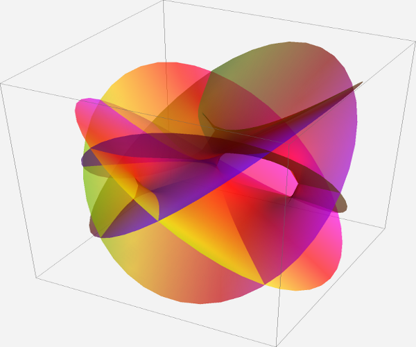
A more interesting exploration is looking at the fractal in three dimensions. In particular, I want to examine the Riemann surface structure in more detail. I think separating out the sheets of the surface will expose much more of the fractal structure, which gets hidden when all the sheets are projected together. I tried to compute the Riemann surface for just two iterations of a similar function using Mathematica but the result is almost incomprehensible:

Riemann surce of (z^2+.z)^.5

Riemann surce of (z^2+.z)^.5
RiemannSurfacePlot3D[ w == (z^2.5+z)^.5, Re[w], {z, w}, PlotPoints -> {46, 44}, ImageSize -> 1260, Coloring -> Hue[Im[w]/8]]/. gc_GraphicsComplex :> {Opacity[0.66], gc} Multi-sheet z^2.5+c fractal at (-.90, 1.14): 5 iterations, edges of escape regions
An alternative way to compute the multi-branch fractal is to walk around the edge of the fractal. The result should be similar to the edge pictures above. However, walking pixel-by-pixel would have a few advantages. First, it would be much more efficient, allowing a much deeper iteration count which should show interesting fractal structure. Second, walking around only part of the edge will keep parts of the fractal from obscuring other parts.

I think the orbit behavior of individual starting points is a key to understanding this fractal. For instance, which starting points yield a 1-cycle, 2-cycle, and so forth. It's hard to define these cycles exactly, because of the multi-value nature of the fractal. A value can converge to a fixed point on one branch, but not another.

Another mathematical feature that I think is key to understanding the fractal is points where the value goes to zero. The function has many more zeros than I expected, and they are concentrated at "interesting" points of the fractal. The zeros are where the Riemann surfaces come together, and also the points where the boundary forms "loops".

I've been exploring different ways of displaying cycles and zeros, and hope to post images soon, but this post is already very long, so I'll leave those for Part II.

Related work

Many people have generated Mandelbrots with non-integer exponents, but always using a single-valued function. Wikipedia has a summary under the title Multibrot set.

I started investigating multi-branch fractional exponents many years ago but computers weren't powerful enough at the time, so my investigation didn't get very far. My negative integer exponents were easier to compute and I wrote a paper about those fractals: ``An Investigation of z -> 1/z^n+c,'' Computers & Graphics, 17(5), Sep. 1993, pp 603-607.

Joshua Sasmor has done an extensive investigation of non-integer exponents in his PhD thesis "Fatou, Julia and Mandelbrot Sets for Functions with Non-Integer Exponent" and in the paper "Fractals for functions with rational exponent", Computers and Graphics 28(4). Also of interest is his presentation Julia Set and Branch Cuts which shows the Julia set for z^2.5 - 1/2 + i/10 using inverse iteration instead of escape time. I suspect that his inverse iteration Julia set algorithm yields results similar to applying my multi-branch algorithm to Julia sets. I haven't explored this yet, but if true, it would provide more evidence that the multi-branch algorithm gives the "real" structure of the fratals.

There are several interesting videos that show the evolution of the generalized Mandelbrot set as the exponent changes. A few examples are Mandelbrot Set from 1 to 100 with zoom, Cut along negative X axis, and Cut along negative Y axis. It is interesting to compare the last two, to see how different the results are if the branch cut is placed in a different location.

Conclusion

The multi-branch algorithm provides an interesting new way to display Mandelbrot-like fractals that have non-integer exponents