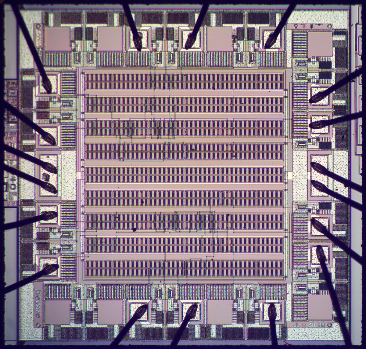
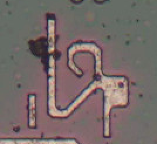
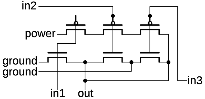
I recently came across an interesting die photo of a Soviet
1 chip, probably designed in the 1970s.
This article provides an introductory guide to reverse-engineering CMOS circuits, using this chip as an
example.
Although the chip looks like a tangle of lines at first,
its large features and simple layout make it possible to understand its circuits.
I'll first explain how to recognize the individual transistors.
Groups of transistors are connected in standard patterns to form CMOS gates, multiplexers, flip-flops, and other circuits.
Once these building blocks are understood, reverse-engineering the full chip becomes practical.
The chip turned out to be a 4-bit CMOS counter, a copy of
the Motorola
MC14516B.
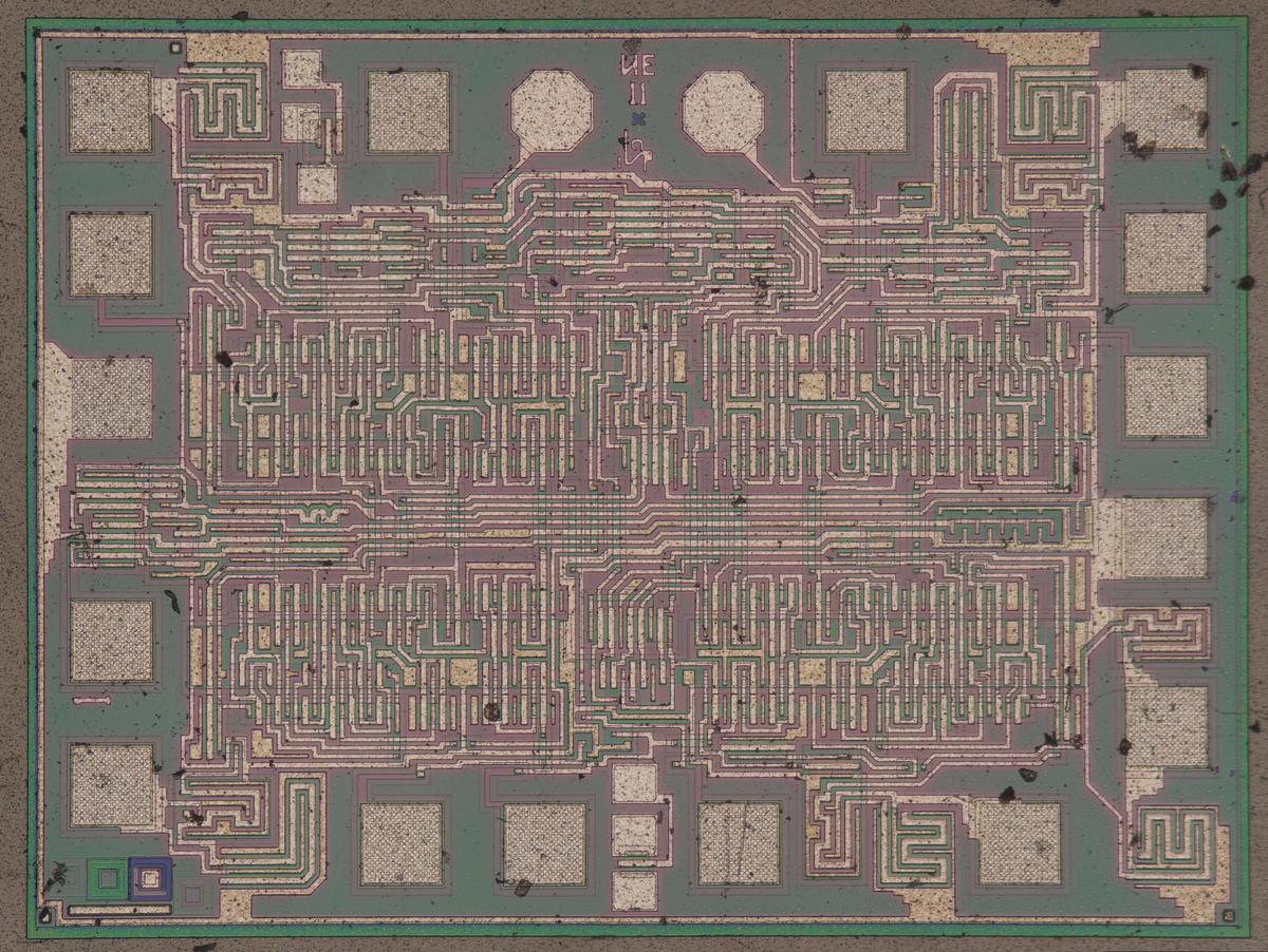
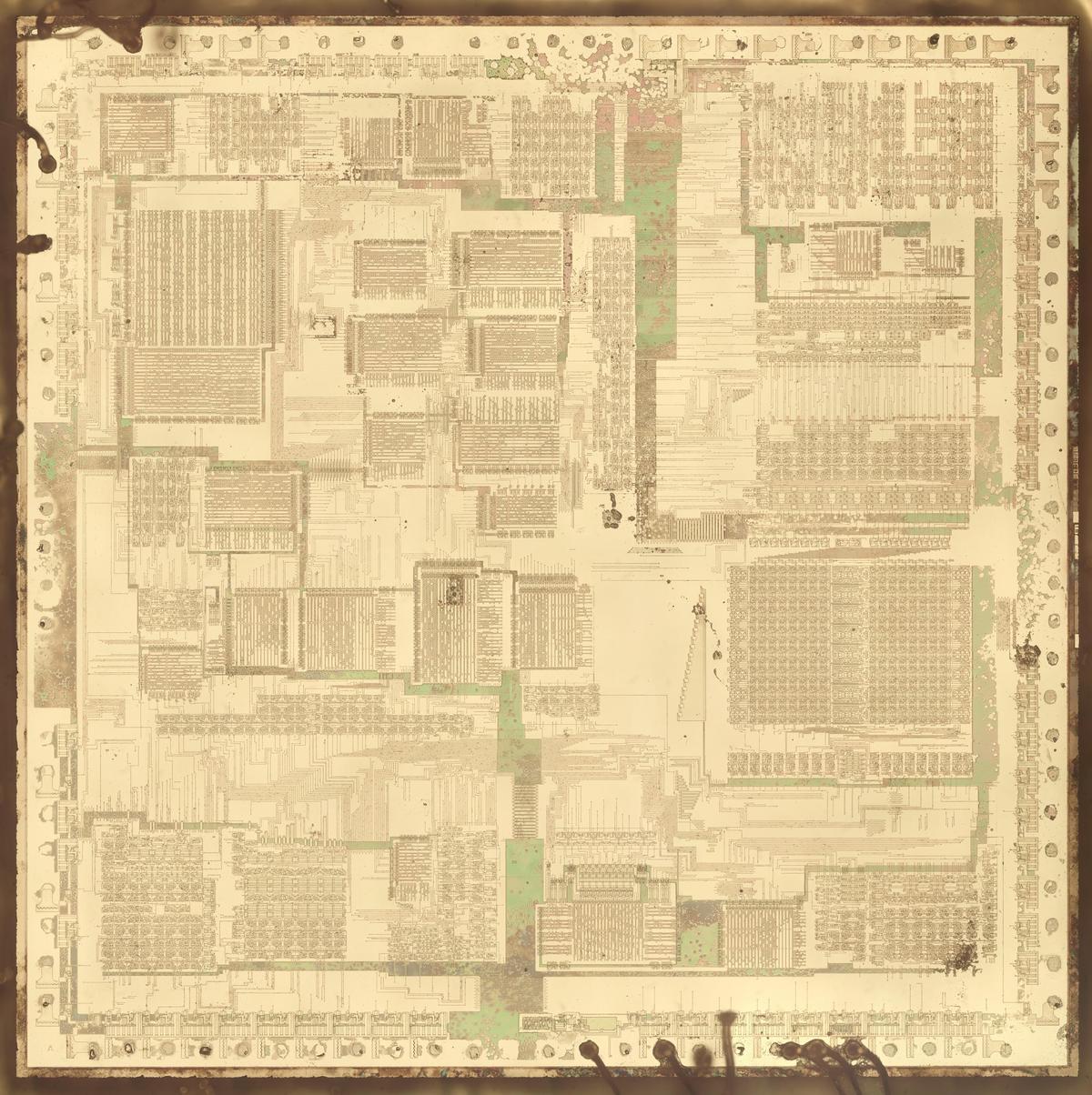
Die photo of the К561ИЕ11 chip on a wafer. Image courtesy of
Martin Evtimov. Click this image (or any other) for a larger version.
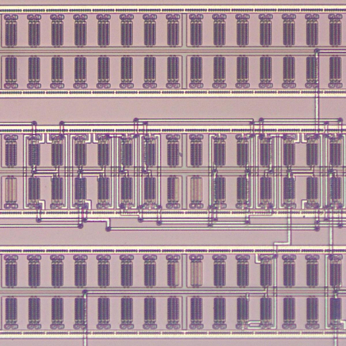
The photo above shows the tiny silicon die under a microscope.
Regions of the silicon are doped with impurities to change the silicon's electrical properties.
This doping also causes regions of the silicon to appear greenish or reddish, depending on how a region is doped.
(These color changes will turn out to be useful for reverse engineering.)
On top of the silicon, the whitish metal layer is visible, forming the chip's connections.
This chip uses metal-gate transistors, an old technology, so the metal layer also forms the gates of the transistors.
Around the outside of the chip, the 16 square bond pads connect the chip to the outside world.
When installed in a package, the die has tiny bond wires between the pads and the lead frame, the metal
structure that connects to the chip's pins.
According to the Russian datasheet,2 the chip has 319 "elements", presumably counting the semiconductor devices. The chip has a handful of diodes
to protect the inputs,
so the total transistor count is a bit over 300.
This transistor count is nothing compared to a modern CMOS processor with tens of billions of transistors,
of course, but most of the circuit principles are the same.
NMOS and PMOS transistors
CMOS is a low-power logic family now used in almost all processors.3
CMOS (complementary MOS) circuitry uses two types of transistors, NMOS and PMOS, working together.
The diagram below shows how an NMOS transistor is constructed.
The transistor can be considered a switch between the source and drain, controlled by the gate.
The source and drain regions (red) consist of silicon doped with impurities to change its semiconductor properties, forming N+ silicon.
The gate consists of an aluminum layer, separated from the silicon by a very thin insulating oxide layer.4
(These three layers—Metal, Oxide, Semiconductor—give the MOS transistor its name.)
This oxide layer is an insulator, so there is essentially no current flow through the gate, one reason why
CMOS is a low-power technology.
However, the thin oxide layer is easily destroyed by static electricity, making MOS integrated circuits sensitive
to electrostatic discharge.
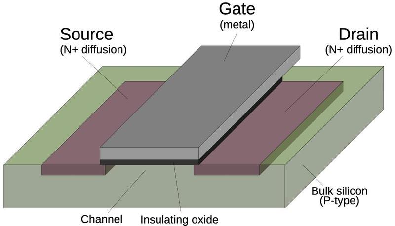
Structure of an NMOS transistor.
A PMOS transistor (below) has the opposite configuration from an NMOS transistor: the source and drain are doped to form P+ regions, while the
underlying bulk silicon is N-type silicon.
The doping process is interesting, but I'll leave the details to a footnote.5
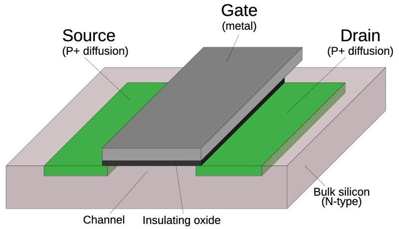
Structure of a PMOS transistor.
The NMOS and PMOS transistors are opposite in their construction and operation; this is the "Complementary" in CMOS.
An NMOS transistor turns on when the gate is high, while a PMOS transistor turns on when the gate is low.
An NMOS transistor is best at pulling its output low, while a PMOS transistor is best at pulling its output high.
In a CMOS circuit, the transistors work as a team, pulling the output high or low as needed.
The behavior of MOS transistors is complicated, so this description is simplified, just enough to understand
digital circuits.
If you buy an MOS transistor from an electronics supplier, it comes as a package with three leads for the
source, gate, and drain. The source and drain are connected differently inside the package and are not interchangeable in
a circuit.
In an integrated circuit, however, the transistor is symmetrical and the source and drain are the same.
For that reason, I won't distinguish between the source and the drain in the following discussion.
I will use the symmetrical symbols below for NMOS and PMOS transistors; the inversion bubble on the PMOS gate
symbolizes that a low signal activates the PMOS transistor.
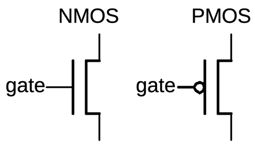
Symbols for NMOS and PMOS transistors.
One complication is that NMOS transistors are built on
P-type silicon, while PMOS transistors are built on N-type silicon.
Since the silicon die itself is N silicon, the NMOS transistors need to be surrounded by
a tub or well of P silicon.6 The cross-section diagram below shows how the NMOS transistor on the right is embedded in the well of P-type silicon.
Constructing two transistor types with opposite behaviors makes manufacturing more complex, one reason why CMOS
took years to catch on.
CMOS was invented in 1963 at Fairchild Semiconductor, but RCA was the main proponent of CMOS, commercializing it
in the late 1960s. Although RCA produced a CMOS microprocessor in 1974, mainstream microprocessors didn't
switch to CMOS until the mid-1980s with chips such as the Motorola 68020 (1984) and the Intel 386 (1986).
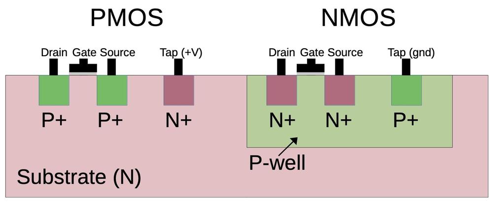
Cross-section of CMOS transistors.
For proper operation, the silicon that surrounds transistors needs to be connected to the appropriate voltage through
"tap" contacts.7
For PMOS transistors, the substrate is connected to power through the taps, while for NMOS transistors the well region is connected to ground through the taps.
When reverse-engineering, the taps can provide important clues, indicating which regions are NMOS and which are PMOS.
As will be seen below, these voltages are also important for understanding the circuitry of this chip.
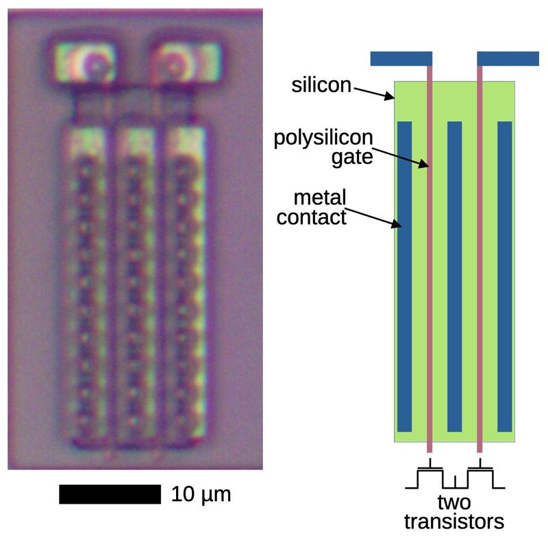
The die photo below shows two transistors as they appear on the die.
The appearance of transistors varies between different integrated circuits, so a first step of
reverse engineering is determining how they look in a particular chip.
In this IC, a transistor gate can be distinguished by a large rectangular region over the silicon.
(In other metal-gate transistors, the gate often has a "bubble" appearance.)
The interactions between the metal wiring and the silicon can be distinguished by subtle differences.
For the most part, the metal wiring passes over the silicon, isolated by thick insulating oxide.
A contact between metal and silicon is recognizable by a smaller oval region that is slightly darker;
wires are connected to the transistor sources and drains below.
MOS transistors often don't have discrete boundaries; as will be seen later, the source of one transistor can overlap with the drain of another.
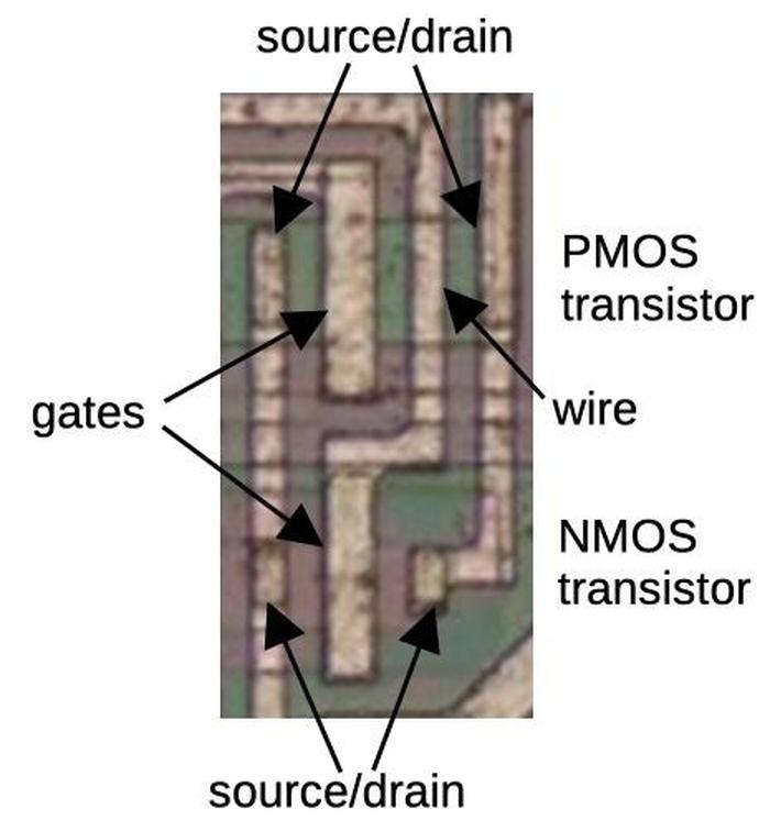
Two transistors on the die.
Distinguishing PMOS and NMOS transistors can be difficult.
On this chip, P-type silicon appears greenish, and N-type silicon appears reddish.
Thus, PMOS transistors appear as a green region surrounded by red, while NMOS is the opposite.
Moreover, PMOS transistors are generally larger than NMOS transistors because they are weaker.
Another way to distinguish them is by their connection in circuits.
As will be seen below, PMOS transistors in logic gates are connected to power while NMOS
transistors are connected to ground.
Metal-gate transistors are a very old technology, mostly replaced by silicon-gate transistors in the 1970s.
Silicon-gate circuitry uses an additional layer of polysilicon wiring. Moreover, modern ICs usually have more
than one layer of metal.
The metal-gate IC in this post is easier to understand than a modern IC, since there are fewer layers to analyze.
The CMOS principles are the same in modern ICs, but the layout will appear different.
Implementing an inverter in CMOS
The simplest CMOS gate is an inverter, shown below. Although basic, it illustrates most of the principles of
CMOS circuitry. The inverter is constructed from a PMOS transistor on top to pull the output high and an NMOS transistor below to pull the output low.
The input is connected to the gates of both transistors.
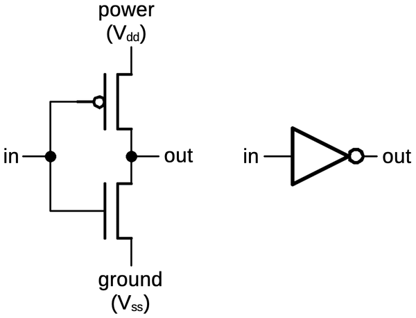
A CMOS inverter is constructed from a PMOS transistor (top) and an NMOS transistor (bottom).
Recall that an NMOS transistor is turned on by a high signal on the gate, while a PMOS transistor is the opposite,
turned
on by a low signal.
Thus, when the input is high, the NMOS transistor (bottom) turns on, pulling the output low.
When the input is low, the PMOS transistor (top) turns on, pulling the output high.
Notice how the transistors act in opposite (i.e. complementary) fashion.
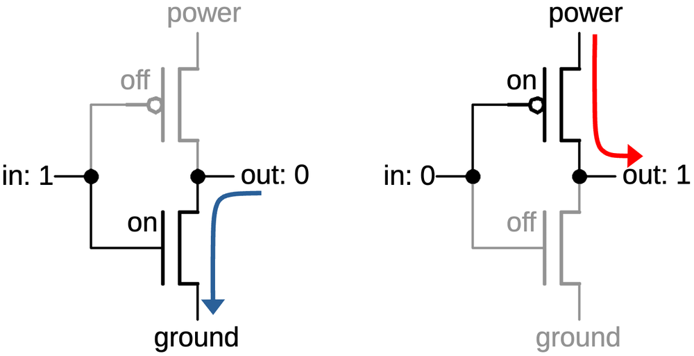
How the inverter functions.
An inverter on the die is shown below. The PMOS and NMOS transistors are indicated by red boxes and
the transistors are connected according to the schematics above.
The input is connected to the gates of the two transistors, which can be distinguished as larger metal rectangles.
On the right, two contacts connect the transistor drains to the output.
The power and ground connections are a bit different from most chips since the metal lines appear to not
go anywhere.
The short metal line labeled "power" connects the PMOS transistor's source to the substrate, the reddish silicon
that surrounds the transistor.
As described earlier, the substrate is connected to the chip's power.
Thus, the transistor receives its power through the substrate silicon.
This approach isn't optimal, due to the relatively high resistance of silicon, but it simplifies the wiring.
Similarly, the ground metal connects the NMOS transistor's source to the well that surrounds the transistor,
P-type silicon that appears green.
Since the well is grounded, the transistor has its ground connection.
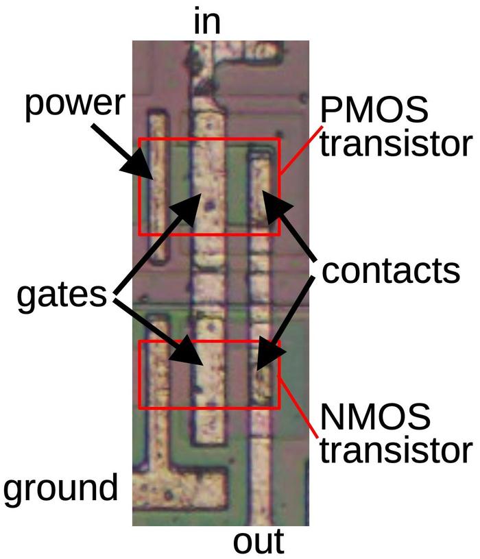
An inverter on the die.
Some inverters look different from the layout above.
Many of the chip's inverters are constructed as two inverters in parallel to provide twice the output current.
This gives the inverter more "fan-out", the ability to drive the inputs of a larger number of gates.8
The diagram below shows a doubled inverter, which is essentially the previous inverter mirrored and copied,
with two PMOS transistors at the top and two NMOS transistors at the bottom.
Note that there is no explicit boundary between the paired transistors; their drains share the same silicon.
Consequently, each output contact is shared between two transistors, rather than being duplicated.
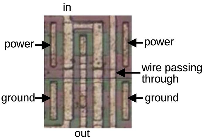
An inverter consisting of two inverters in parallel.
Another style of inverter drives the chip's output pins.
The output pins require high current to drive external circuitry. The chip uses much larger transistors
to provide this current.
Nonetheless, the output driver uses the same inverter circuit described earlier, with a PMOS transistor
to put the output high and an NMOS transistor to pull the output low.
The photo below shows one of these output inverters on the die.
To fit the larger transistors into the available space, the transistors have a serpentine layout,
with the gate winding
between the source and the drain.
The inverter's output is connected to a bond pad.
When the die is mounted in a package, tiny bond wires connect the pads to the external pins.
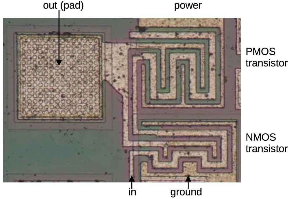
An output driver is an inverter, built with much larger transistors.
NOR and NAND gates
Other logic gates are constructed using the same concepts as the inverter, but with additional transistors.
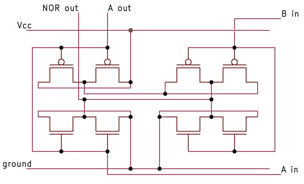
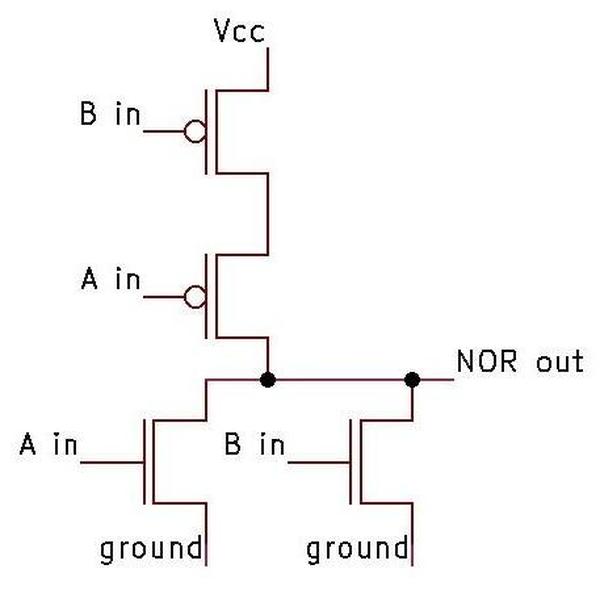
In a NOR gate,
the PMOS transistors on top are in series, so the output will be pulled high if all inputs are 0.
The NMOS transistors on the bottom are in parallel, so the output will be pulled low if any input is 1.
Thus, the circuit implements the NOR function.
Again, note the complementary action: the PMOS transistors pull the output high, while the NMOS transistors
pull the output low. Moreover, the PMOS transistors are in series, while the NMOS transistors are in parallel.
The circuit below is a 3-input NOR gate; different numbers of inputs are supported similarly.
(With just one input, the circuit becomes an inverter, as you might expect.)
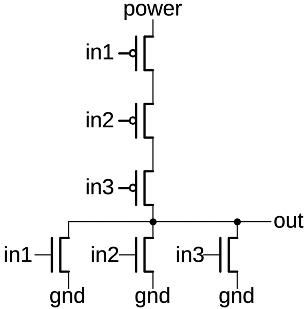
A 3-input NOR gate implemented in CMOS.
For any gate implementation, the input must be either pulled high by the PMOS side, or pulled low by the NMOS side.
If both happen simultaneously for some input, power and ground would be shorted, possibly destroying the chip. If neither
happens, the output would be floating, which is bad in a CMOS circuit.9
In the NOR gate above, you can see that for any input the output is always pulled either high or low as required.
Reverse engineering tip: if the output is not always pulled high or low, you probably made a mistake in either the PMOS circuit or
the NMOS circuit.10
The diagram below shows how a 3-input NOR gate appears on the die.11
The transistor gates are the thick vertical metal rectangles; PMOS transistors are on top and NMOS below.
The three PMOS transistors are in series between power on the left and the output connection on the right.
As with the inverter, the power and ground connections are wired to the bulk silicon, not to the chip's power and ground lines.
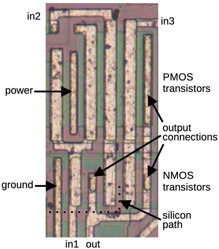
A 3-input NOR gate as it is implemented on the die. The "extra" PMOS transistor on the left is part of a different gate.
The layout of the NMOS transistors is more complicated because it is difficult to wire the transistors in parallel with just one layer of metal.
The output wire connects between the first and second transistors as well as to the third transistor.
An unusual feature is the connection of the second and third NMOS transistors to ground is done by
a horizontal line of doped silicon (reddish "silicon path" indicated by the dotted line).
This silicon extends from the ground metal to the region between the two transistors.
Finally, note that the PMOS transistors are much larger than the NMOS transistors. This is both because PMOS
transistors are inherently less efficient and because transistors in series need to be lower resistance
to avoid degrading the output signal.
Reverse-engineering tip: It's often easier to recognize the transistors in series and then use that information
to determine which transistors must be in parallel.
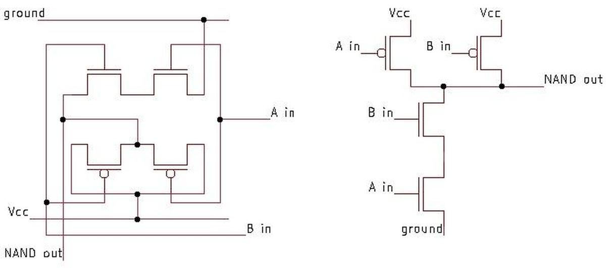
A NAND gate is implemented by swapping the roles of the series and parallel transistors. That is, the PMOS transistors
are in parallel, while the NMOS transistors are in series.
For example, the schematic below shows a 4-input NAND gate.
If all inputs are 1, the NMOS transistors will pull the output low.
If any input is a 0, the corresponding PMOS transistor will pull the output high.
Thus, the circuit implements the NAND function.
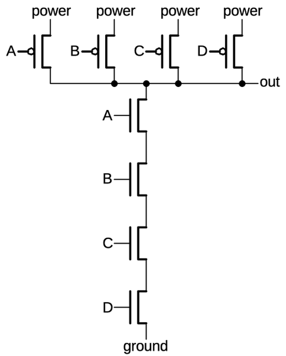
A 4-input NAND gate implemented in CMOS.
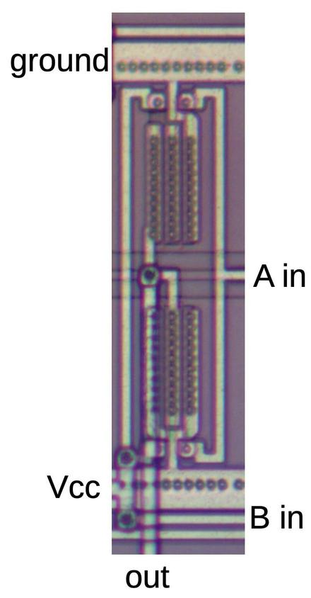
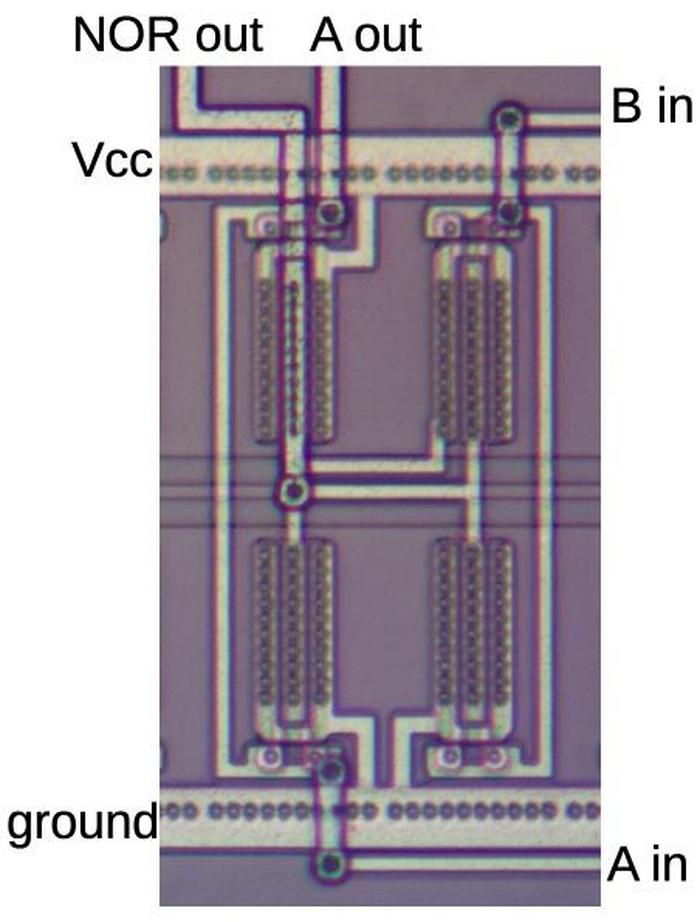
The diagram below shows a four-input NAND gate on the die.
In the bottom half, four NMOS transistors are in series, while in the top half, four PMOS transistors are in
parallel. (Note that the series and parallel transistors are switched compared to the NOR gate.)
As in the NOR gate, the power and ground are provided by metal connections to the bulk silicon (two connections
for the power).
The parallel PMOS circuit uses a "silicon path" (green) to connect
each transistor to the output without intersecting the metal.
In the middle, this silicon has a vertical metal line on top; this reduces the resistance of the silicon path.
The NMOS transistors are larger than the PMOS transistors in this case because the NMOS transistors are in series.
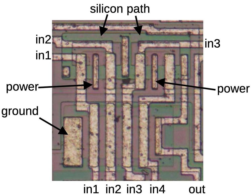
A four-input NAND gate as it appears on the die.
Complex gates
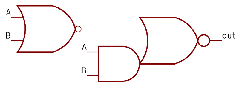
More complex gates such as AND-NOR (AND-OR-INVERT) can also be constructed in CMOS; these gates are commonly
used because they are no harder to build than NAND or NOR gates.
The schematic below shows an AND-NOR gate.
To understand its construction, look at the paths to ground through the NMOS transistors.
The first path is through A, B, and C. If these inputs are all high, the output is low, implementing the
AND-INVERT side of the gate. The second path is through D, which will pull the output low by itself, implementing
the OR-INVERT side of the gate.
You can verify that the PMOS transistors pull the output high in the necessary circumstances.
Observe that the D transistor is in series on the PMOS side and in parallel on the NMOS side, again showing
the complementary nature of these circuits.
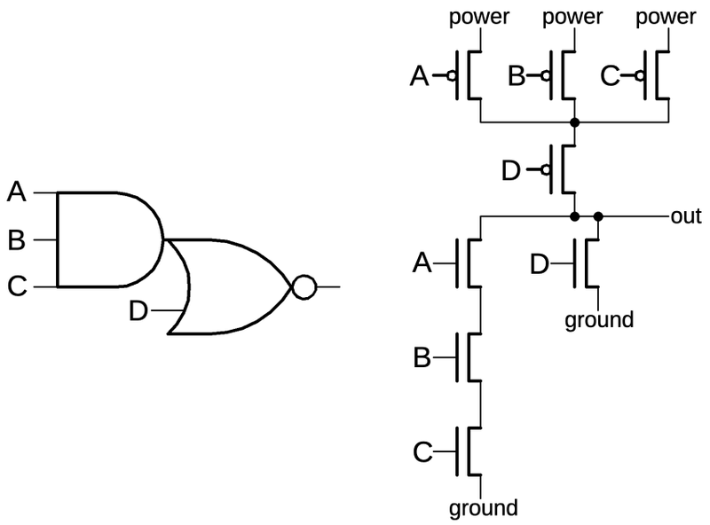
An AND-NOR gate.
The diagram below shows this AND-NOR gate on the die, with the four inputs
A, B, C, and D, corresponding to the schematic above.
This gate has a few tricky layout features.
The biggest surprise is that there is half of another gate (a 3-input NOR gate) in the middle of this gate.
Presumably, the designers found this arrangement efficient since the other gate also uses inputs A, B, and C. The output
of the other gate (D) is an input to the gate we're examining.
Ignoring the other gate, the AND-NOR gate has the NMOS transistors in the first column, on top of a reddish band,
and the PMOS transistors in the third column, on top of a greenish band.
Hopefully you can recognize the transistor gates, the large rectangles connected to A, B, C, and D.
Matching the schematic above, there are three NMOS transistors in series on the left, connected to A, B, and C,
as well as the D transistor providing a second path between ground and the output.
On the PMOS side, the A, B, and C transistors are in parallel, and then connected through the D transistor to
the output.
The green "silicon path" on the right provides the parallel connection from transistors A and B to transistors C and D.
Most of this path is covered by two long metal regions, reducing the resistance.
But in order to cross under wires B and C, the metal has a break where the green silicon provides the connection.
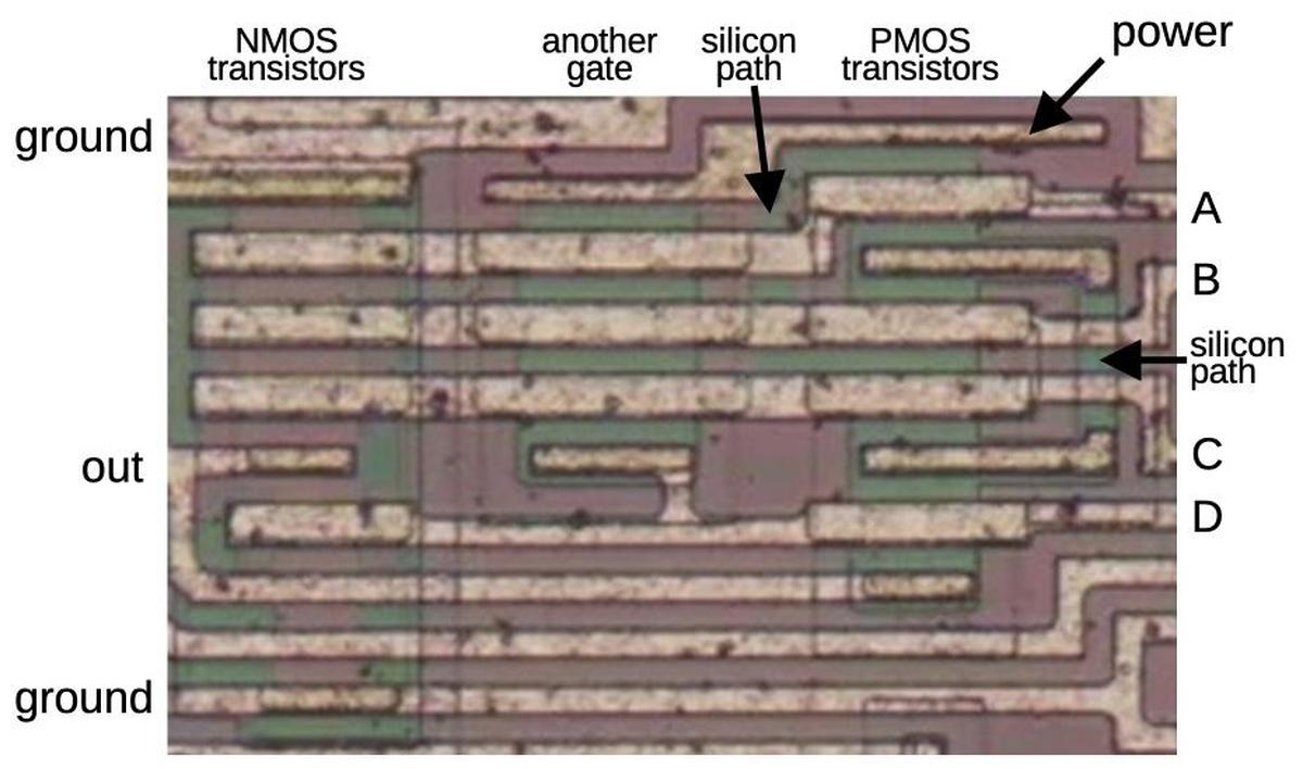
An AND-NOR gate on the die.
As with the other gates, the power is obtained by a connection to the bulk silicon, bridging the red and green regions.
If you look closely, there is a green band ("silicon path") down from the power connection and joining
the main green region between the B and C transistors, providing power to those transistors through the silicon.
The NMOS transistors, on the other hand, have ground connections at the top and bottom.
For this circuit, ground is supplied through solid metal wires at the top and the bottom, rather than a connection to the bulk silicon.
A few principles help when reverse-engineering logic gates.
First, because of the complementary nature of CMOS, the output must either be pulled high by the PMOS transistors
or pulled low by the NMOS transistors.
Thus, one group or the other must be activated for each possible input.
This implies that the same inputs must go to both the NMOS and PMOS transistors.
Moreover, the structures of the NMOS and PMOS circuits are complementary: where the NMOS transistors are parallel,
the PMOS transistors must be in series, and vice versa.
In the case of the AND-NOR circuit above, these principles are helpful.
For instance, you might not spot the "silicon paths", but since the PMOS half must be complementary to the NMOS
half, you know that those connections must exist.
Even complex gates can be reverse-engineered by breaking the NMOS transistors into series and parallel groups,
corresponding to AND and OR terms. Note that MOS transistors are inherently inverting, so a single gate will
always end with inversion. Thus, you can build an AND-OR-AND-NOR gate for instance, but you can't build
an AND gate as a single circuit.
Transmission gate
Another key circuit is the transmission gate. This acts as a switch, either passing a signal through or blocking it.
The schematic below shows how a transmission gate is constructed from two transistors, an NMOS transistor and a PMOS transistor.
If the enable line is high (i.e. low to the PMOS transistor) both transistors turn on, passing the input signal to the output.
The NMOS transistor primarily passes a low signal, while the PMOS transistor passes a high signal, so they
work together.
If the enable line is low, both transistors turn off, blocking the input signal.
The schematic symbol for a transmission gate is shown on the right.
Note that the transmission gate is bidirectional; it doesn't have a specific input and output.
Examining the surrounding circuitry usually reveals which side is the input and which side is the output.
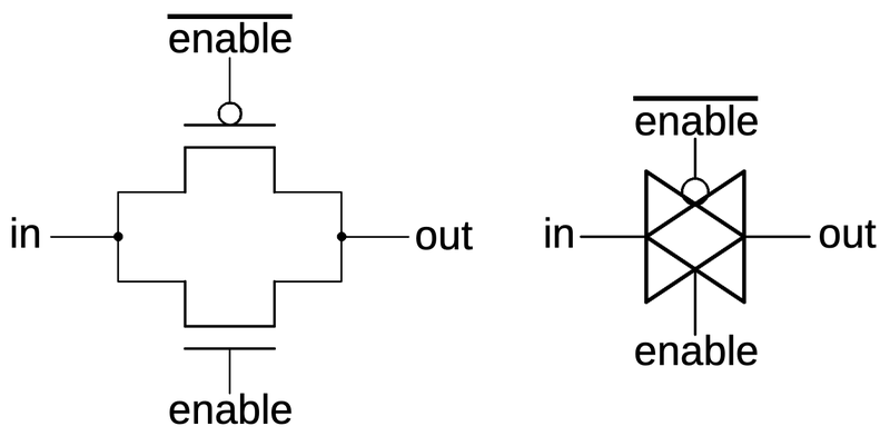
A transmission gate is constructed from two transistors. The transistors and their gates are indicated. The schematic symbol is on the right.
The photo below shows how a transmission gate appears on the die.
It consists of a PMOS transistor at the top and an NMOS transistor at the bottom.
Both the enable signal and the complemented enable signal are used, one for the NMOS transistor's gate and
one for the PMOS transistor.
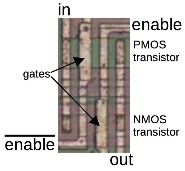
A transmission gate on the die, consisting of two transistors.
The inverter and transmission gate are both two-transistor circuits, but they can be easily distinguished
for reverse engineering.
One difference is that an inverter is connected to power and ground, while the transmission gate is unpowered.
Moreover, the inverter has one input, while the transmission gate has three inputs (counting the control lines).
In the inverter, both transistor gates have the same input, so one transistor turns on at a time.
In the transmission gate, however, the gates have opposite inputs, so the transistors turn on or off together.
One useful circuit that can be built from transmission gates is the multiplexer, a circuit that selects one of two (or more) inputs.
The multiplexer below selects either input inA or inB and connects it to the output, depending if the selection line selA is high or low respectively.
The multiplexer can be built from two transmission gates as shown. Note that the select lines are flipped on
the second transmission gate, so one transmission gate will be activated at a time.
Multiplexers with more inputs can be built by using more transmission gates with additional select lines.
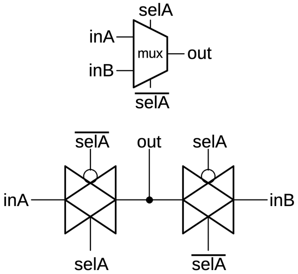
Schematic symbol for a multiplexer and its implementation with two transmission gates.
The die photo below shows a block of transmission gates consisting of six PMOS transistors and six NMOS transistors.
The labels on the metal lines will make more sense as the reverse engineering progresses.
Note that the metal layer provides much of the wiring for the circuit, but not all of it.
Much of the wiring is implicit, in the sense that neighboring transistors are
connected because the source of one transistor overlaps the drain of another.
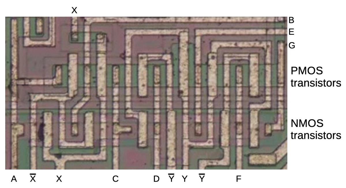
A block of transistors implementing multiple transmission gates.
While this may look like an incomprehensible block of zig-zagging lines, tracing out the transistors will
reveal the circuitry (below).
The wiring in the schematic matches the physical
layout on the die, so the schematic is a bit of a mess.
With a single layer of metal for wiring, the layout becomes a bit convoluted to avoid crossing wires.
(The only wire crossing in this image is in the upper left for wire X; the signal uses a short stretch of
silicon to pass under the metal.)

Schematic of the previous block of transistors.
Looking at the PMOS and NMOS transistors as pairs reveals that the circuit above is a chain of transmission gates (shown below).
It's not immediately obvious which wires are inputs and which wires are outputs, but it's a good guess that
pairs of transmission gates using the opposite control lines form a multiplexer. That is, inputs A and C
are multiplexed to output B, inputs C and E are multiplexed to output D, and so forth.
As will be seen, these transmission gates form multiplexers that are part of a flip-flop.

The transistors form six transmission gates.
Latches and flip-flops
Flip-flops and latches are important circuits, able to hold one bit and controlled by a clock signal.
Terminology is inconsistent, but I'll use flip-flop to refer to an edge-triggered device and latch
to refer to a level-triggered device.
That is, a flip-flop will grab its input at the moment the clock signal goes high (i.e. it uses the clock edge),
store it, and provide it as the output, called Q for historical reasons.
A latch, on the other hand, will take its input, store it, and output it as long as the clock is high
(i.e. it uses the clock level).
The latch is considered "transparent", since the input immediately appears on the output if the clock is high.
The distinction between latches and flip-flops may seem pedantic, but it is important.
Flip-flops will predictably update once
per clock cycle, while latches will keep updating as long as the clock is high.
By connecting the output of a flip-flop through an inverter back to the input, you can create a toggle flip-flop,
which will flip its state once per clock cycle, dividing the clock by two.
(This example will be important shortly.)
If you try the same thing with a transparent latch, it will oscillate: as soon as the output flips, it will
feed back to the latch input and flip again.
The schematic below shows how a latch can be implemented with transmission gates. When the clock is high,
the first transmission gate passes the input through to the inverters and the output.
When the clock is low, the second transmission gate creates a feedback loop for the inverters, so they
hold their value, providing the latch action.
Below, the same circuit is drawn with a multiplexer, which may be easier to understand:
either the input or the feedback is selected for the inverters.
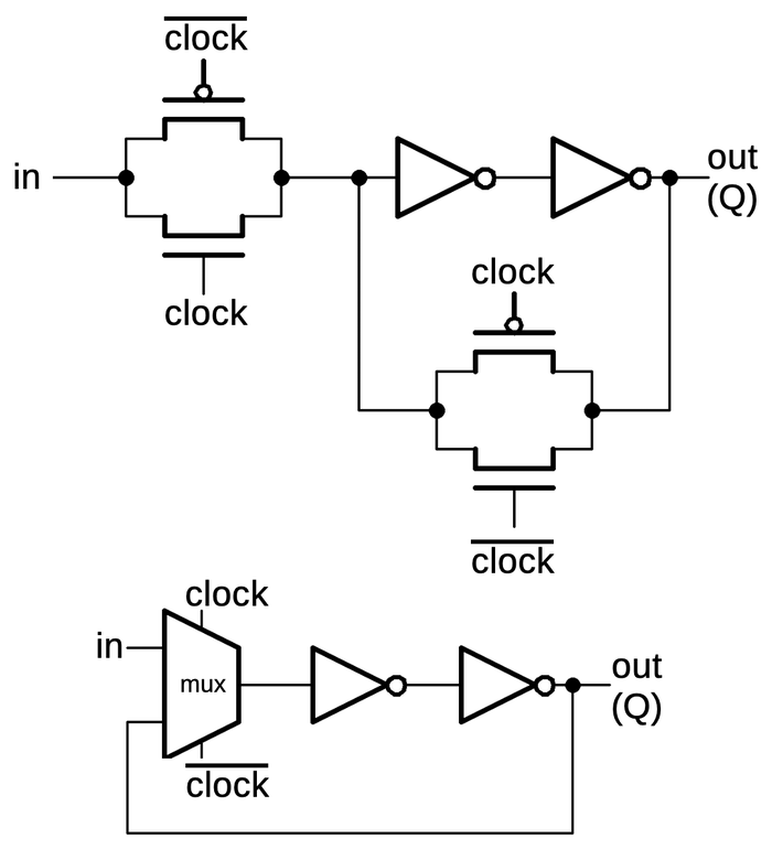
A latch implemented from transmission gates. Below, the same circuit is shown with a multiplexer.
An edge-triggered flip-flop can be created by combining two latches in a primary/secondary arrangement.
When the clock is low, the input will pass into the primary latch.
When the clock switches high, two things happen. The primary latch will hold the current value of the input.
Meanwhile, the secondary latch will start passing its input (the value from the primary latch) to its output,
and thus the flip-flop output.
The effect is that the flip-flop's output will be the value at the moment the clock goes high, and the
flip-flop is insensitive to changes at other times. (The primary latch's value can keep changing while the clock is
low, but this doesn't affect the flip-flop's output.)

Two latches, combined to form a flip-flop.
The flip-flops in the counter chip are based on the above design, but they have two additional features.
First, the flip-flop can be loaded with a value under the control of a Preset Enable (PE) signal.
Second, the flip-flop can either hold its current value or toggle its value, under the control of a Toggle (T)
signal.
Implementing these features requires two more multiplexers in the primary latch as shown below.
The first multiplexer selects either the inverted output or uninverted output to be fed back into the flip
flop, providing the selectable toggle action.
The second multiplexer is the latch's standard clocked multiplexer. The third multiplexer allows a
"preset" value to be loaded directly into the flip-flop, bypassing the clock.
(The preset value is inverted, since there are three inverters between the preset and the output.)
The secondary latch is the same as before, except it provides the inverted and non-inverted outputs as
feedback, allowing the flip-flop to either hold or toggle its value.
This circuit illustrates how more complex flip-flops can be created from the building blocks that we've seen.

Schematic of the toggle flip-flop.
The gray letters in the schematic above match the earlier multiplexer diagram, showing how the
three multiplexers were implemented on the die.
The other multiplexer and the inverters are implemented in another block of circuitry.
I won't explain that circuitry in detail since it doesn't illustrate any new principles.
Routing in silicon: cross-unders
With just one metal layer for wiring, routing of signals on the chip is difficult and requires careful planning.
Even so, there are some cases where one signal must cross another.
This is accomplished by using silicon for a "cross-under", allowing a signal to pass underneath metal wiring.
These cross-unders are avoided unless necessary because silicon has much higher resistance than metal.
Moreover, the cross-under requires additional space on the die.
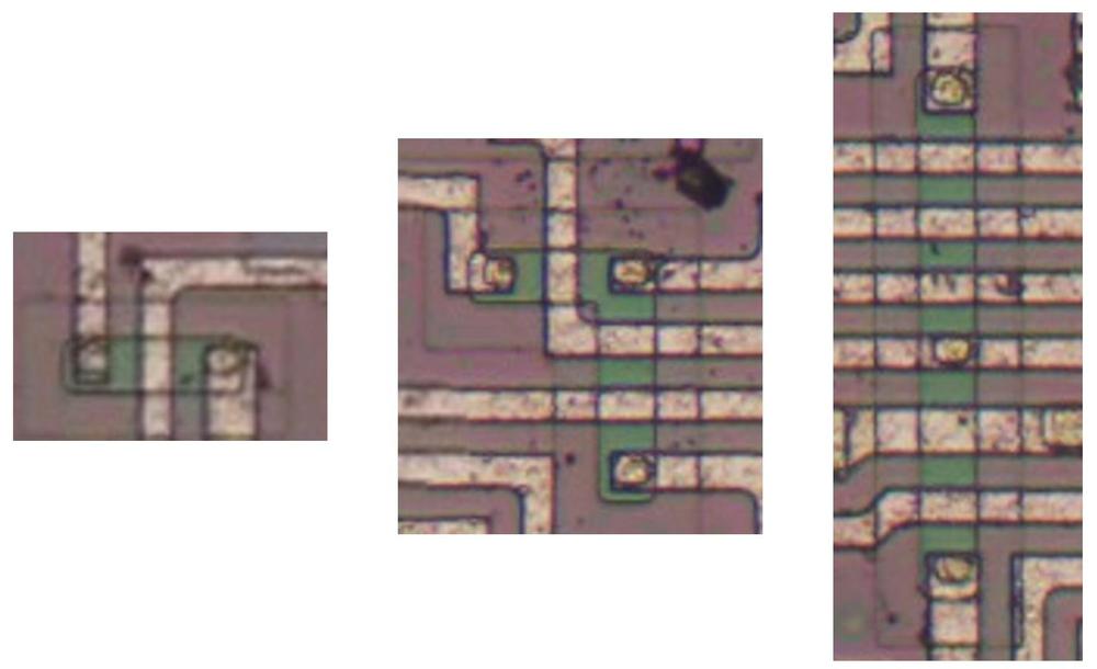
Three cross-unders on the die.
The images above show three cross-unders. In each one, signals are primarily routed in the metal layer,
but a signal passes under the metal using a doped silicon region (which appears green).
The first cross-under simply lets one signal cross under the second.
The second image shows a signal branching as well as crossing under two signals.
The third image shows a cross-under distributing a horizontal signal to the upper and lower halves of the chip, while
crossing under multiple horizontal signals.
Note the small oval contact between the green silicon region and the horizontal metal line, connecting them.
It is easy to miss the small contact and think that the vertical signal is simply crossing under the horizontal
signal, rather than branching.
About the chip
The focus of this article is the CMOS reverse engineering process rather than this specific chip, but
I'll give a bit of information about the chip.
The die has the Cyrillic characters ИЕ11 at the top indicating that the chip is a К561ИЕ11 or К564ИЕ11.12
The Soviet Union came up with a standardized numbering system for integrated circuits in 1968.
This system is much more helpful than the American system of semi-random part numbers.
In this part number, the 5 indicates a monolithic integrated circuit, while 61 or 64 is the series, specifically commercial-grade or military-grade
clones of 4000 series CMOS logic.
The character И indicates a digital circuit, while ИЕ is a counter.
Thus, the part number systematically indicates that the integrated circuit is a CMOS counter.
The 561ИЕ11 turns out to be a copy of the Motorola MC14516 binary up/down counter.13
Conveniently, the Motorola datasheet provides a schematic (below).
I won't explain the schematic in detail, but a quick overview may be helpful.
The chip is a four-bit counter that can count up or down, and the heart of the chip is the four toggle flip-flops (red).
To count up, a flip-flop is toggled if there is a carry from the lower bits, while counting down toggles
a flip-flop if there is a borrow from the lower bits. (Much like base-10 long addition or subtraction.)
The AND/NOR gates at the bottom (blue) look complex, but they are just generating the toggle signal T:
toggle if the lower bits are all-1's and you're counting up, or if the lower bits are all-0's and you're
counting down.
The flip-flops can also be loaded in parallel from the P inputs.
Additional logic allows the chips to be cascaded to form arbitrarily large counters;
the carry-out pin of one chip is connected to the carry-in of the next.
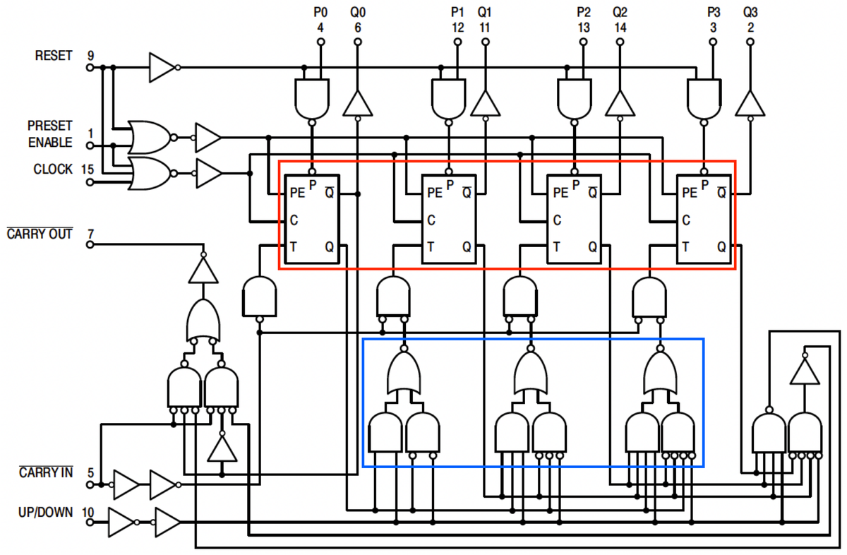
Logic diagram of the MC14516 up/down counter chip, from the
datasheet.
I've labeled the die photo below with the pin functions and the functional blocks.
Each quadrant of the chip handles one bit of the counter in a roughly symmetrical way.
This quadrant layout accounts for the pin arrangement which otherwise appears semi-random with bits 3 and 0
on one side and bits 2 and 1 on the other, with inputs and output pins jumbled together.
The toggle and carry logic is squeezed into the top and middle of the chip.
You may recognize the large inverters next to each output pin.
When reverse-engineering, look for large transistors next to pads to determine which pins are outputs.
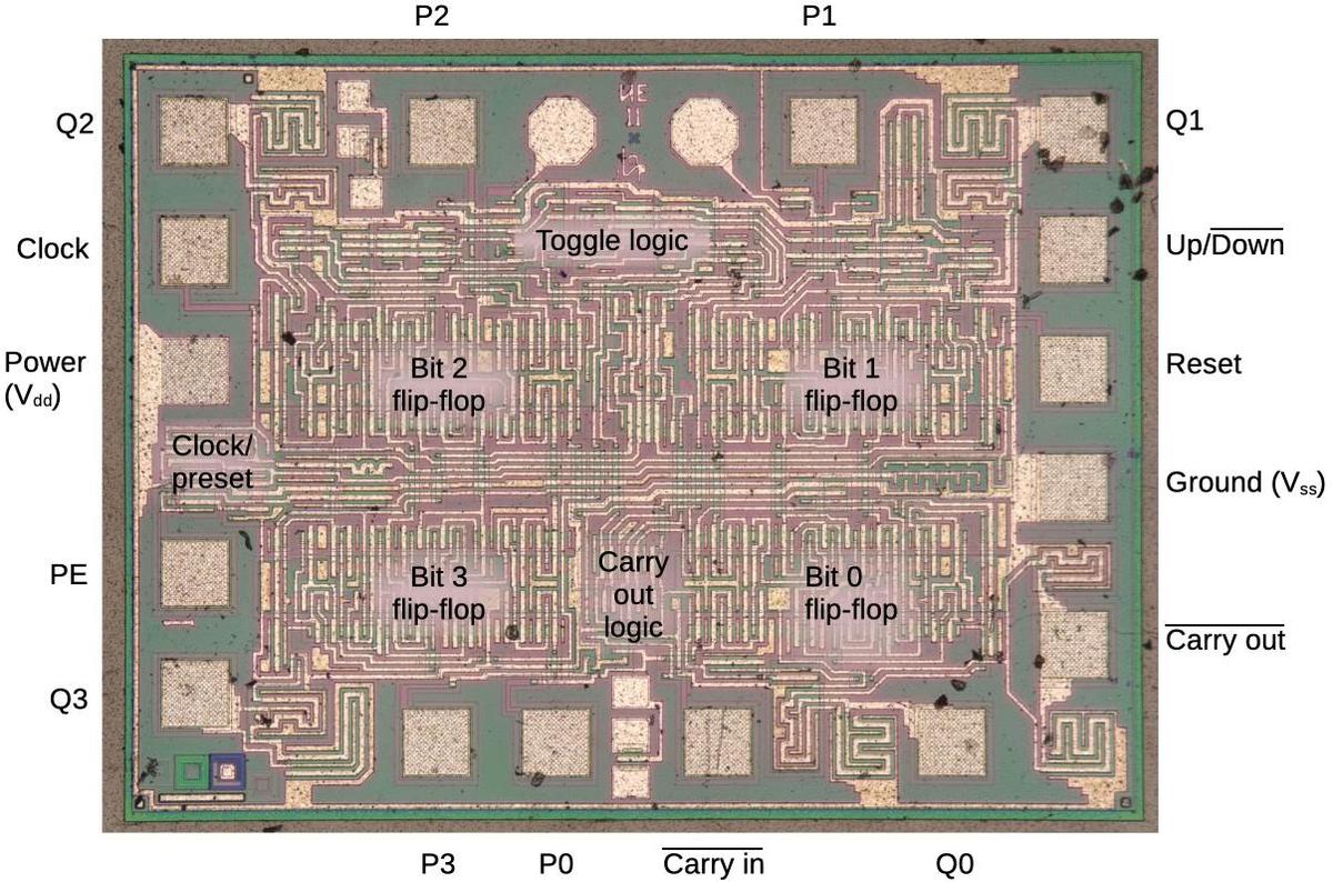
The die with pins and functional blocks labeled.
Conclusions
This article has discussed the basic circuits that can be found in a CMOS chip.
Although the counter chip is old and simple, later chips use the same principles.
An important change in later chips is the introduction of silicon-gate transistors, which use polysilicon for the transistor gates and for
an additional wiring layer.
The circuits are the same, but you need to be able to recognize the polysilicon layer.
Many chips have more than one metal layer, which makes it very hard to figure out the wiring connections.
Finally, when the feature size approaches the wavelength of light, optical microscopes break down.
Thus, these reverse-engineering techniques are only practical up to a point.
Nonetheless, many interesting CMOS chips can be studied and reverse-engineered.
For more,
follow me on Twitter @kenshirriff or RSS for updates.
I'm also on Mastodon as @[email protected].
Thanks to
Martin Evtimov for providing the die photos.
Notes and references







![The Keystone II board. The box is labeled Keystone II FCS [i.e. First Customer Shipment] July 23, 1982. Photo from bitsavers, originally from Bob Roberts. The Keystone II board. The box is labeled Keystone II FCS [i.e. First Customer Shipment] July 23, 1982. Photo from bitsavers, originally from Bob Roberts.](https://static.righto.com/images/ibm-3274/keystone-ii-w600.jpg)

