Showing posts with label beaglebone. Show all posts

Reading a VGA monitor's configuration data with I2C and a PocketBeagle

Have you ever wondered how your computer knows all the characteristics of your monitor— the supported resolutions, the model, and even the serial number? Most monitors use a system called DDC to communicate this information to the computer.1 This information is transmitted using the I2C communication protocol—a protocol also popular for connecting hobbyist devices. In this post, I look inside a VGA monitor cable, use a tiny PocketBeagle (a single-board computer in the BeagleBone family) to read the I2C data from an LCD monitor, and then analyze this data.

Inside a VGA cable. The cable is more complex than I expected, with multiple layers of shields. The green, red, white (sync) and blue wires are thicker and have their own shielding.

Inside a VGA cable. The cable is more complex than I expected, with multiple layers of shields. The green, red, white (sync) and blue wires are thicker and have their own shielding.

To connect to the monitor, I cut a VGA cable in half and figured out which wire goes to which pin.3 The wire (above) is constructed in an interesting way, more complicated than I expected. The red, green, blue and horizontal sync signals are transmitted over coaxial-like cables formed by wrapping a wire a spiral of thin copper wires for shielding.2 The remaining signals travel over thinner plain wires. Several strands of string form the structural center of the VGA cable, and the ten internal wires are wrapped in a foil shield and woven outer shield.

The VGA connector consists of 3 rows of 5 pins.
Pins are simply numbered left-to-right with 1 through 5 in the first row, 6-10 in the second, and 11-15 in the third.
(Click image for a closeup.)

The VGA connector consists of 3 rows of 5 pins. Pins are simply numbered left-to-right with 1 through 5 in the first row, 6-10 in the second, and 11-15 in the third. (Click image for a closeup.)

The photo above shows the male VGA connector on each end of the cable. The function assigned to each pin is shown in the table below. The I2C clock (SCL) and data (SDA) are the important pins for this project. The wire colors are not standardized; they refer to my VGA cable and may be different for a different cable.

PinFunctionWire color
1RedRed coax
2GreenGreen coax
3BlueBlue coax
4ReservedShield
5GroundBlack
6Red GroundShield
7Green GroundShield
8Blue GroundShield
95VYellow
10GroundWhite
11ReservedShield
12SDAGreen
13HSyncWhite coax
14VSyncBrown
15SCLRed

The 5 volt wire in the cable has a clever purpose. This wire allows the computer to power the EEPROM chip that provides the configuration data. Thus, the computer can query the display's characteristics even if the display is turned off or even unplugged from the wall.

Reading the configuration data

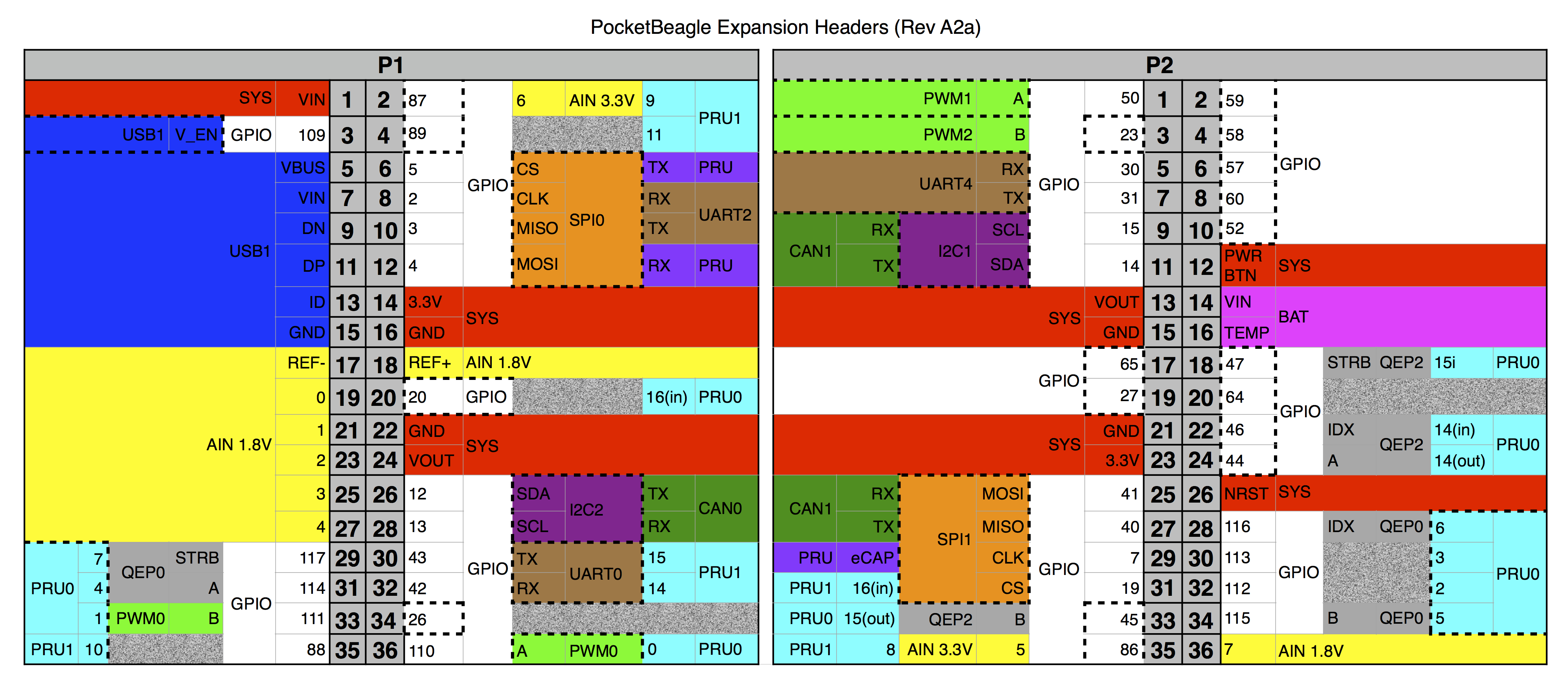
To read the data over I2C, I used the PocketBeagle, a tiny Linux computer that I had handy. (You could use a different system that supports I2C, such as the Raspberry Pi, Beaglebone or Arduino.) I simply connected the I2C clock (SCL), data (SDA) and ground wires from the VGA cable to the PocketBeagle's I2C pins as shown below.

Connecting a VGA cable to the PocketBeagle allows the configuration data to be read over I2C. The black wire is ground, the green wire is I2C data (SDA) and the red wire is I2C clock (SCL).

Connecting a VGA cable to the PocketBeagle allows the configuration data to be read over I2C. The black wire is ground, the green wire is I2C data (SDA) and the red wire is I2C clock (SCL).

Simple Linux commands let me access I2C. First, I probed the I2C bus to see what devices were present, using the i2cdetect command. (Many devices can be connected to an I2C bus, each assigned a different address.) The output below shows that devices 30, 37, 4a, 4b and 50 responded on I2C bus 1. Device 50 is the relevant I2C device, assigned to the configuration information. Device 37 is DDC/CI, allowing monitor settings to be controlled by the computer, but I'll ignore it for this post. Devices 30, 4a, and 4b are a mystery to me so leave a comment if you know what they are.

$ i2cdetect -y -r 1
     0  1  2  3  4  5  6  7  8  9  a  b  c  d  e  f
00:          -- -- -- -- -- -- -- -- -- -- -- -- --
10: -- -- -- -- -- -- -- -- -- -- -- -- -- -- -- --
20: -- -- -- -- -- -- -- -- -- -- -- -- -- -- -- --
30: 30 -- -- -- -- -- -- 37 -- -- -- -- -- -- -- --
40: -- -- -- -- -- -- -- -- -- -- 4a 4b -- -- -- --
50: 50 -- -- -- -- -- -- -- -- -- -- -- -- -- -- --
60: -- -- -- -- -- -- -- -- -- -- -- -- -- -- -- --
70: -- -- -- -- -- -- -- --

Next, I used the i2cdump command to read 128 bytes from device 50's registers, providing the raw VGA information. The hex values are on the left and ASCII is on the right.

$ i2cdump -y -r 0-127 1 0x50 b
     0  1  2  3  4  5  6  7  8  9  a  b  c  d  e  f    0123456789abcdef
00: 00 ff ff ff ff ff ff 00 04 69 fa 22 01 01 01 01    ........?i?"????
10: 12 19 01 03 1e 30 1b 78 ea 3d 25 a3 59 51 a0 25    ?????0?x?=%?YQ?%
20: 0f 50 54 bf ef 00 71 4f 81 80 81 40 95 00 a9 40    ?PT??.qO???@?.?@
30: b3 00 d1 c0 01 01 02 3a 80 18 71 38 2d 40 58 2c    ?.?????:??q8-@X,
40: 45 00 dd 0c 11 00 00 1e 00 00 00 fd 00 32 4c 1e    E.???..?...?.2L?
50: 53 11 00 0a 20 20 20 20 20 20 00 00 00 fc 00 56    S?.?      ...?.V
60: 45 32 32 38 0a 20 20 20 20 20 20 20 00 00 00 ff    E228?       ....
70: 00 46 34 4c 4d 51 53 31 32 38 35 34 36 0a 00 bb    .F4LMQS128546?.?

Understanding the monitor's EDID data

The configuration data is encoded in the EDID (Extended Display Identification Data) format, so it's not immediately obvious what the data means. But the format is well-documented, so it's not too hard to figure out. For instance, the first 8 bytes 00 ff ff ff ff ff ff 00 are the header. The next two bytes 04 69 encode three 5-bit characters for the manufacturer ID, in this case "ACI" - Asus Computer International. (The data format uses a lot of annoying bit manipulations like these to make the data compact.) Near the end of the output, the ASCII strings "VE228" and "F4LMQS128546" are clearly visible; these are the monitor's model number and serial number.

I made a simple Python program to decode the data, giving the following results:

Header:
  Manufacturer: ACI
  Product code: 8954
  Week: 18
  Year: 2008
  Edid version 1, revision 3
  Analog input
  Levels: +0.7/-.03
  Blank-to-black setup (pedestal) expected
  Separate sync supported
  Composite sync supported
  Sync on green supported
  Horizontal screen size: 48cm
  Vertical screen size: 27cm
  Display gamma: 2.200
  DPMS standby supported
  DPMS suspend supported
  DPMS active-off supported
  Display type (analog): RGB color
  Preferred timing mode in descriptor block 1
Chromaticity coordinates:  r: (0.637, 0.351), g: (0.319, 0.626), b: (0.145, 0.061), w: (0.313, 0.329)
Established timings:
  720x400 @ 70 Hz
  640x480 @ 60 Hz
  640x480 @ 67 Hz
  640x480 @ 72 Hz
  640x480 @ 75 Hz
  800x600 @ 56 Hz
  800x600 @ 60 Hz
  800x600 @ 72 Hz
  800x600 @ 75 Hz
  832x624 @ 75 Hz
  1024x768 @ 60 Hz
  1024x768 @ 72 Hz
  1024x768 @ 75 Hz
  1280x1024 @ 75 Hz
Standard timing information:
  X res: 1152, aspect 4:3, Y res (derived): 864), vertical frequency: 75
  X res: 1280, aspect 5:4, Y res (derived): 1024), vertical frequency: 60
  X res: 1280, aspect 4:3, Y res (derived): 960), vertical frequency: 60
  X res: 1440, aspect 16:10, Y res (derived): 900), vertical frequency: 60
  X res: 1600, aspect 4:3, Y res (derived): 1200), vertical frequency: 60
  X res: 1680, aspect 16:10, Y res (derived): 1050), vertical frequency: 60
  X res: 1920, aspect 16:9, Y res (derived): 1080), vertical frequency: 60
Descriptor 1: Detailed timing descriptor:
  Pixel clock: 148500kHz
  Horizontal active pixels: 1920
  Horizontal blanking pixels: 280
  Vertical active lines: 1080
  Vertical blanking lines: 45
  Horizontal front porch pixels: 88
  Horizontal sync pulse pixels: 44
  Vertical front porch lines: 4
  Vertical sync pulse lines: 5
  Horizontal image size: 477mm
  Vertical image size: 268mm
  Horizontal border pixels: 0
  Vertical border lines: 0
  Digital separate sync
  VSync serration
  Positive horizontal sync polarity
Descriptor 2: Display range limits
  Minimum vertical field rate 50Hz
  Maximum vertical field rate 76Hz
  Minimum horizontal field rate 30Hz
  Maximum horizontal field rate 83Hz
  Maximum pixel clock rate: 170Mhz
  Default GTF
Descriptor 3: Display name VE228
Descriptor 4: Display serial number F4LMQS128546

As you can see, the EDID format crams a lot of configuration information into 128 bytes. The output starts off with some basic data about the monitor's characteristics and inputs. The VGA standard doesn't nail down as many things as you'd hope. For instance the sync signals can be provided on one wire (composite), two wires (separate), or on the green wire. The output above shows my monitor supports all three sync types.

The monitor then provides a long list of supported resolutions, which is how your computer knows what the monitor supports. The "detailed timing descriptor" provides more information on signal voltage levels and timings. The timing of VGA signals contains some strange features (e.g. blanking and "front porch") inherited from obsolete CRT (Cathode Ray Tube) displays. The values in the configuration provide the information necessary for the computer's graphics board to synthesize a proper VGA signal that the monitor can understand.

The CIE chromaticity coordinates provided by the monitor are interesting, but need a bit of background to understand. A CIE chromaticity diagram (below), shows all the colors in the real world. (Brightness is factored out, so grays and browns don't appear.) Individual wavelengths of light (i.e. the spectrum) curve around the outside of the diagram. The colors inside the curve are combinations of the pure spectral colors, with white in the middle.

CIE diagram showing the color gamut and white point of my monitor.

CIE diagram showing the color gamut and white point of my monitor.

A display, however, generates its colors by combining red, green, and blue. The result is that a display can only show the colors inside the triangle above with red, green, and blue at the corners. A display doesn't generate the light wavelengths necessary to display colors outside the triangle. Like most monitors, this monitor can only show a surprisingly small fraction of the possible colors. (A wide-gamut display uses different phosphors to expand the triangle and get more vivid colors.) The triangle vertices and white point4 in the diagram above come from the x,y chromaticity coordinates in the configuration data.

You might wonder how you can see the whole CIE diagram on your display if only the colors inside the triangle can be displayed. The answer is the diagram "cheats"—the colors are scaled to fit into RGB values, so you're not seeing the exact colors but just an approximate representation. If you look at the spectrum through a prism, for instance, the colors will be more intense than what you see in the CIE diagram.

Inside I2C

The I2C protocol (Inter-Integrated Circuit) was invented in 1982 by Philips Semiconductor to connect a CPU to peripheral chips inside televisions. It's now a popular protocol for many purposes, including connecting sensors, small LED displays, and other devices to microcontrollers. Many I2C products are available from Adafruit and Sparkfun for instance.

The I2C protocol provides a simple, medium-speed way to connect multiple devices on a bus using just two wires—one for a clock and one for data. I2C is a serial protocol, but it differs from serial protocols like RS-232 in a couple ways. First, I2C is synchronous (using a clock), unlike RS-232 which is asynchronous (no clock). Second, I2C is a bus and can connect dozens of devices, while RS-232 connects two devices.5

The oscilloscope trace below shows what an I2C communication with the monitor looks like on the wire. The top line (cyan) shows the clock. Note that the clock only runs while data is transmitted.) The yellow line is the binary data. At the bottom, the oscilloscope decoded the data (green). In this trace, register number 0x26 is being read from device 0x50. The I2C protocol is rather peculiar since a read is performed by doing a write followed by a read. That is, to read a byte, the master first does a write to the device of the desired register number: the master first sends 0x50 (the device ID) the write flag bit (indicated with "W:50"), and 0x26 (the register number, ASCII "&"). Then, the master does a read; it sends 0x50 and the read flag bit ("R:50"). The device responds with the value in the register, 0x71 (ASCII "q").6

I2C trace: clock (SCL) in cyan and data (SDA) in yellow. Green shows decoded data. Oscilloscope was set to 20µs/division and 2V/division.

I2C trace: clock (SCL) in cyan and data (SDA) in yellow. Green shows decoded data. Oscilloscope was set to 20µs/division and 2V/division.

Devices on the I2C bus can only pull a line low; pull-up resistors keeps the lines high by default.7 As a result, the traces above drop low sharply, but climb back up slowly.8 Even though the transitions look sloppy, the I2C bus worked fine. I couldn't find a source to tell me if VGA monitors included pull-up resistors, or if I needed to add them externally. However, I measured voltage on the lines coming from the monitor and everything worked without external resistors, so there must be pull-up resistors inside the monitor.

Conclusion

The VGA specification includes a data link that allows a computer to learn about a monitor and configure it appropriately. It is straightforward to read this configuration data using the I2C protocol and a board with an I2C port. While VGA is mostly obsolete now, the same data protocol is used with DVI and HDMI displays. My goal in reading the monitor's config data was so I could use the timing data in an FPGA to generate a VGA video signal. (That project is yet to come.) Follow me on Twitter or RSS to find out about my latest blog posts.

Notes and references

  1. DDC (Display Data Channel) is used by VGA, DVI and HDMI connections, which transmit the data over two I2C pins. The data it sends is in the EDID (Extended Display Identification Data) format. Everything changed with the DisplayPort interface. It transmits configuration data over a differential AUX channel using the DisplayID format, which extends EDID to supports newer features such as 3D displays. Thus, the techniques I describe in this article should work with DVI or HDMI interfaces, but won't work with DisplayPort. 

  2. Looking at other VGA cables on the web, most VGA cables don't have the fourth coax for horizontal sync that my cable does. So my cable seems a bit unusual. 

  3. Instead of cutting a VGA cable in half, I could have simply plugged a cable into a VGA connector, but that's less interesting. 

  4. The white point for my monitor matches a standard called D65

  5. For more information on I2C, good explanations are on SparkFun and Wikipedia

  6. I'm leaving out some of the complications of I2C. For example, the master generates the clock, but the device can do "clock stretching" by holding the clock low until it is ready. Also, the device sends an ACK bit after each request. The device address is 7 bits, while the data is 8 bits. See protocol documentation for details. 

  7. Using a pull-up resistor on the I2C bus avoids the risk of short circuits. If, alternatively, devices could actively pull the line high, it would be a problem if one device tried to pull a line high at the same time another pulled it low. 

  8. The oscilloscope traces show exponential R-C charging curves when the line is pulled high. This is due to the wire capacitance being charged through the pull-up resistor. The signals only reach about 3V, making them suitable for the PocketBeagle's 3.3V inputs. (If you try this with a different monitor, check the voltage levels to avoid damaging the PocketBeagle's inputs.) 

Xerox Alto's 3 Mb/s Ethernet: Building a gateway with a BeagleBone

The Alto was a revolutionary computer designed at Xerox PARC in 1973. It introduced the GUI, high-resolution bitmapped displays, the optical mouse and laser printers to the world. But one of its most important contributions was Ethernet, the local area network that is still heavily used today. While modern Ethernets handle up to 100 gigabits per second, the Alto's Ethernet was much slower, just 3 megabits per second over coaxial cable. Even so, the Alto used the Ethernet for file servers, email, distributed games, network boot, and even voice over Ethernet.

The Alto's 3 Mb/s Ethernet isn't compatible with modern Ethernet, making it difficult to transfer data between an Alto and the outside world. To solve this, I built a gateway using the BeagleBone single-board computer to communicate with the Alto's Ethernet. In this article I discuss how the Alto's Ethernet works and how I implemented the gateway.

The Alto's Ethernet hardware

The Alto's Ethernet used a coaxial cable, rather than modern twisted-pair cable. A transceiver box was the interface between the Alto and the cable, converting the Alto's logic signals to the signals on the cable. In the photo below, you can see a transceiver clamped onto the coaxial cable; a "vampire tap" punctures the cable making contact with the central conductor.

Inside a transceiver box. The "vampire tap" on the right connects the transceiver to the Ethernet cable. The connector on the left goes to the Alto.

Inside a transceiver box. The "vampire tap" on the right connects the transceiver to the Ethernet cable. The connector on the left goes to the Alto.

The Alto's Ethernet uses Manchester encoding of the bits. That is, a "1" is sent as "10" and a "0" is sent as "01". The reason to do this instead of just sending the raw bits is the Manchester encoding is self-clocking—there's a transition for every bit. If instead you just sent a raw stream of bits, e.g. "00000000000", the receiver would have a hard time knowing where the bits start and end. The figure below shows how 0110 is transmitted with Manchester encoding.

An example of Manchester encoding, for the bits 0110.

An example of Manchester encoding, for the bits 0110.

The Alto's network protocols

The Alto predates TCP/IP, instead using a protocol called Pup (the PARC Universal Packet).1 The protocol has many similarities with TCP/IP, since the Pup designers influenced the TCP design based on their experience. The basic Pup Internet Datagram is analogous to an IP packet. A packet contains a destination address for the packet consisting of a network id (1 byte), a host id on the network (1 byte), and a 4-byte socket. A machine's host id is specified by jumper wires on the backplane (below). Thus, packets can be routed through a large network to the right machine.

Long blue jumper wires on the Alto's backplane specify the system's Ethernet address.

Long blue jumper wires on the Alto's backplane specify the system's Ethernet address.

Some simple network operations just exchanged Pup packets, for example requesting the time from a network server. But for more complex operations, Xerox built layers on top of Pup. For a long-lived connection between two machines, Xerox built RTP (Rendezvous/Termination Protocol), a protocol to establish connections between two ports. This is analogous to a TCP socket connection. Once the connection is established, the computers can communicate using Byte Steam Protocol (BSP). This protocol handles error correction and flow control, very similar to TCP.

On top of these protocols, Xerox implemented email, FTP (File Transfer Protocol), network boot, networked games such as Maze War, network error reporting, network disk backups and the first computer worm.

Map of the Xerox PARC network, showing important servers. May 1978. From Alto User's Primer.

Map of the Xerox PARC network, showing important servers. May 1978. From Alto User's Primer.

Designing an Ethernet gateway

I decided to build a gateway that would allow the Alto to communicate with a modern system. The gateway would communicate with the Alto using its obsolete 3Mb/s Ethernet, but could also communicate with the outside world. This would let us network boot the Alto, transfer files to and from the Alto and backup disks. I expected this project to take a few weeks, but it ended up taking a year.

The first decision was what hardware platform to use. My plan was to use a microcontroller to generate the 3Mb/s signals by "bit banging", i.e. directly generating the 1's and 0's on the wire. (A regular processor couldn't handle this in real time, due to interrupts and task switching.) But a microcontroller wouldn't be suitable for running the network stack and communicating with the outside world; I'd need a "real computer" for that. Someone suggested the BeagleBone: a credit-card sized Linux computer with an ARM processor that also incorporated two microcontrollers. This would provide a compact, low-cost implementation, so I started investigating the BeagleBone.

The BeagleBone single-board Linux computer is small enough to fit in an Altoids tin. It has many general/purpose I/O pins, accessible through the connectors along the top and bottom of the board.

The BeagleBone single-board Linux computer is small enough to fit in an Altoids tin. It has many general/purpose I/O pins, accessible through the connectors along the top and bottom of the board.

The BeagleBone's microcontrollers, called PRUs,2 are designed to run each instruction in a single 5ns cycle. Since the Ethernet pulses are 170ns wide, I figured I had plenty of time to send and receive signals. (It turned out that getting everything done in 170ns was challenging, but it worked out in the end.) In my gateway, the PRU reads the Ethernet signal coming from the Alto, and generate the Ethernet signal going to the Alto, as well as sending a network collision signal to the Alto.

In case you're wondering what PRU code looks like, the C code fragment below shows how a byte is encoded and sent. The PRU code outputs the right sequence of HIGH/LOW or LOW/HIGH pulses (the Manchester encoding), making sure each part is 170ns wide. Each bit of register R30 controls an output pin, so the bit for the Ethernet write pin is set and cleared as needed. wait_for_pwm_timer() provides the 170ns timing for each pulse. The full code is here.

To receive data from Ethernet, my PRU code doesn't do any decoding; it just measures the time between input transitions and sends these timings to the BeagleBone's ARM processor. Originally my code decoded the Manchester encoding into bits and assembled the bits into words, but 170ns wasn't enough time to do this reliably. Instead, since this decoding doesn't need to be done in real time, I moved the decoding to the more powerful ARM processor. The ARM processor also does the higher-level Ethernet protocol handling, such as generating and checking packet checksums.

Rather than deal with transceivers and coaxial cable, I connected the BeagleBone to the Alto's Ethernet port directly, omitting the transceiver that normally connects to this port. This port provides standard 5V TTL signals to the transceiver, but the BeagleBone inconveniently uses 3.3V signals. I needed a circuit to translate the voltage levels between the BeagleBone and the Alto. This should have been easy, but I ran into various problems along the way.

On the back of the Alto, Ethernet is accessed via a DB-25 connector that connects to a transceiver box.

On the back of the Alto, Ethernet is accessed via a DB-25 connector that connects to a transceiver box.

I built a prototype voltage translation circuit on a breadboard, using a 74AHCT125 level shifter chip (schematic). However, I was getting no Ethernet signal at all from the Alto, so I started probing the Alto's board for a malfunction. I discovered that although the Alto's schematic showed pull-up resistors, these resistors didn't exist on the Alto's Ethernet board (see photo below). Without a resistor, the open-collector signal stayed at ground. Adding the resistors to my circuit fixed that problem.

One problem I encountered was termination resistors R8 and R9 appeared on the schematic but were missing from the board (above the word "ETHERNET").

One problem I encountered was termination resistors R8 and R9 appeared on the schematic but were missing from the board (above the word "ETHERNET").

The next step was to write the PRU microcontroller code to send and receive Ethernet packets. After a lot of testing with the Alto's Ethernet Diagnostic Program (EDP), I was able to echo packets back and forth between the BeagleBone gateway and the Alto.

The Ethernet Diagnostic Program can be used to test the Ethernet. It has a simple GUI.

The Ethernet Diagnostic Program can be used to test the Ethernet. It has a simple GUI.

To be useful, the gateway must support the network stack: Pup packets, network booting, Alto-style FTP and so forth. I started by rewriting the Alto's network code, making a direct port of the BCPL implementation3 to Python. This turned out to be a mess, because the original implementation depended heavily on the Alto's operating system, which provided multiple threads, so the application could run in one thread and the network code in other threads. I managed to get the stateless low-level Pup packets to work okay, but the higher-level Byte Stream Protocol was a tangle of busy-waiting loops and timeouts.

Fortunately the Living Computers Museum+Lab (LCM+L) came to rescue. Josh Dersch at the museum had written a C# implementation of the Alto's network stack, so I decided to discard my implementation of the network stack. This implementation, called IFS,4 supported the low-level protocols, as well as servers for network operations, FTP, and Copydisk. IFS was a new implementation rather than a direct port like my attempt, and that approach worked much better.

The Living Computers Museum built a 3 Mb/s Ethernet interface using an FPGA chip.

The Living Computers Museum built a 3 Mb/s Ethernet interface using an FPGA chip.

The LCM+L also built an Ethernet interface to the Alto. Theirs was much more complex than mine, consisting of an FPGA chip on a custom PCI card plugged into a PC. Unlike my interface, theirs communicated with a transceiver box, rather than connecting to the Alto directly. Even though the LCM+L's FPGA interface worked for us, I decided to complete my interface board since I liked the idea of a low-cost, compact Ethernet gateway. Their interface is more "realistic", since it connects to a real transceiver and network cable and can work with multiple Altos on a network. (The photo below shows the mini-network connecting the LCM+L interface and an Alto.) On the other hand not everyone has Ethernet transceivers lying around, so mine is more widely usable.

A very short 3 Mb/s Ethernet network, showing two transceivers attached to the coaxial cable. One transceiver is connected to the Alto and the other is connected to the LCM+L gateway card.

A very short 3 Mb/s Ethernet network, showing two transceivers attached to the coaxial cable. One transceiver is connected to the Alto and the other is connected to the LCM+L gateway card.

I made a simple printed circuit board to replace my breadboarded prototype. This was the first circuit board I had designed in about 35 years and technology has certainly changed. Back in the 1980s, I drew circuit board traces with a resist pen on a copper-clad board, and then etched the board in ferric chloride solution from Radio Shack. Now, I designed my board using Eagle, uploaded the file to OSH Park, and received a beautiful circuit board a few days later.

My 3 Mb/s Ethernet interface is a level-shifter card on a BeagleBone. Note the capacitor soldered directly to the driver IC to fix a ringing signal problem.

My 3 Mb/s Ethernet interface is a level-shifter card on a BeagleBone. Note the capacitor soldered directly to the driver IC to fix a ringing signal problem.

Running the LCM+L's IFS software on the BeagleBone took some work since the BeagleBone runs Linux and IFS was written in C# for Windows. By using the Mono platform, I could run most of the C# code on the BeagleBone. However, the LCM+L software stack communicated with the gateway by encapsulating Alto Ethernet packets in a modern Ethernet packet, using a .Net Pcap library to access the raw Ethernet. Unfortunately, this library didn't work with Mono, so I rewrote the IFS encapsulation to use UDP.

At this point the Alto and my BeagleBone implementation communicated most of the time, but there were a few tricky bugs to track down. The first problem was FTP would get sometimes bad packets. Eventually I discovered that I had mixed up byte and word counts in one place, and the large packets from FTP were overflowing the PRU's buffer.

The next problem was that when I used Copydisk to copy a disk pack from the Alto to the BeagleBone, a dropped packet caused the network to lock up after a couple minutes. This was puzzling since the sender should retransmit the lost packet after a timeout and everything should recover (like TCP). After tedious debugging, I found that if the Alto and the BeagleBone transmitted packets close together, a race condition in my code caused a dropped packet.56 Then IFS neglected to send a necessary ack when it received an unexpected packet, so the Alto kept resending the wrong packet. After fixing both my gateway code and the IFS ack, the network ran without problems.

Second version of the interface. Note the blue jumper wire to replace the missing trace.

Second version of the interface. Note the blue jumper wire to replace the missing trace.

My first version of the PCB had a few issues8 so I made a second version (above). I found that the driver chip didn't sink enough current for a long cable, so I replaced it with the chip used by the transceivers (a 7438 open collector NAND gate). I also decided to try KiCad instead of Eagle for the second board. Unfortunately, I made a mistake in KiCad7 and the new board was missing a trace, so I had to solder in a jumper (which you can seen in the photo above).

I probed the Alto's Ethernet card with an oscilloscope to check the signals it was receiving. An extender card from the LCM+L allowed us to access the card.

I probed the Alto's Ethernet card with an oscilloscope to check the signals it was receiving. An extender card from the LCM+L allowed us to access the card.

I tested the new board but it didn't work at all: the Alto wasn't receiving data or sending data. I realized that the new driver chip was a NAND gate so the signals were now inverted. I updated the PRU code to flip LOW and HIGH on the data out signal. The board still didn't work, so I probed the Alto's Ethernet board with an oscilloscope, comparing the signals from the old working board to the new failing board. Strangely, both signals were identical in the Alto and looked fine.

Eventually Marc asked me if there could be something wrong with the collision detection. I realized that the the new NAND driver was also inverting the collision detection signal. Thus, the Alto was seeing constant network collisions and refused to send or receive anything. After fixing this in my PRU software, the new board worked fine. I'm making a third revision of the board to fix the missing trace; hopefully this won't break something else.

An assortment of vintage Ethernet transceivers, along with the tap tools used to drill holes in the Ethernet cable for the vampire tap connection.

An assortment of vintage Ethernet transceivers, along with the tap tools used to drill holes in the Ethernet cable for the vampire tap connection.

Conclusion

The Ethernet gateway project took much more time and encountered more problems than I expected. But it worked in the end, and several Alto owners are now using my gateway. I've open-sourced this interface (the board layout and the gateway software); it's available on github.

The Alto I've been restoring came from YCombinator; the restoration team includes Marc Verdiell, Carl Claunch and Luca Severini. My full set of Alto posts is here and Marc's extensive videos of the restoration are here. Thanks to the Living Computers Museum+Labs for the IFS software.

Follow me on Twitter or RSS to find out about my latest blog posts.

Notes and references

  1. For more information on the Pup protocol, see Pup: An Internetwork Architecture and the Pup Specifications memo.  

  2. Programming the PRU microcontrollers has a difficult learning curve, and it's not nearly as well documented as, say, the Arduino. Based on my experience with the PRU, I wrote some programming tips here and here

  3. The Alto's network code is online; you can look at one of the Pup files here. The code is written in BCPL, which was a predecssor to C. It is very similar to C, but with different syntactic choices. For instance, >> is not a shift but accesses a field in a structure. 

  4. At PARC, IFS was an acronym for Interim File System, an Alto-based distributed file server. It was called interim because an improved system was being developed, but somehow a new system never replaced IFS. 

  5. Most of the time, the BeagleBone and the Alto alternated sending packets. But every second, IFS sent a "breath of life" packet, the packet executed by the Alto to start a network boot. The breath of life packet was part of the original Alto—it simplified the network boot code since the Alto didn't need to request a network boot, but just listen for a second or two. Since the breath of life packet was asynchronous with respect to the other network traffic, eventually it would happen at a bad time for my code, triggering the dropped packet problem. 

  6. The problem with the PRU and the "breath of life" packet was due to how I was sending signals between the PRU and the main BeagleBone processor. When sending a packet, the main processor would signal the PRU, and then wait for a signal back when the packet was sent. When a packet was received, the PRU would send a signal to the main processor. The problem was that the PRU sent the same signal in both cases. So a "packet received" signal at the wrong time could wake up the packet sending code, losing the received packet. Fundamentally, I was treating the signals between the main processor and the PRU as synchronous, when everything was really asynchronous. I rewrote the gateway code so ownership of the send and receive buffers was explicitly transferred between the main processor and the PRU. A signal just indicated that ownership had changed somehow; checking the buffer status showed what exactly had changed. See this discussion for details. 

  7. My error in KiCad was I placed a net label just a bit too far from the wire on the schematic, so the wire wasn't connected to the net. 

  8. My first PCB had a couple issues that I had to hack around. Ringing in the signal to the Alto corrupted it, so I added a damping capacitor. The driver didn't have enough current for an Ethernet cable longer than 10 feet, so I added a pull-down resistor. There were also a couple mechanical issues. The location of the Ethernet jack made it hard to remove the cable, and the board blocked one of the BeagleBone buttons. I also discovered that using a 74HC125 driver chip didn't work at all; just the 74AHCT125 worked. 

Hands-on with the PocketBeagle: a $25 Linux computer with lots of I/O pins

The PocketBeagle is a tiny but powerful inexpensive key-fob-sized open source Linux computer. It has 44 digital I/O pins, 8 analog inputs, and supports multiple serial I/O protocols, making it very useful as a controller. In addition, its processor includes two 200-MHz microcontrollers that allow you to implement low-latency, real-time functions while still having the capabilities of a Linux system This article discusses my experience trying out different features of the PocketBeagle, along with some technical details.

The PocketBeagle is a compact Linux computer, somewhat bigger than a quarter.

The PocketBeagle is a compact Linux computer, somewhat bigger than a quarter.

You may be familiar with the BeagleBone, a credit-card sized computer. The PocketBeagle is very similar to the BeagleBone, but smaller and cheaper. Both systems use TI's 1GHz "Sitara" ARM Cortex-A8 processor, but the PocketBeagle's I/O is stripped-down with 72 header pins compared to 92 on the BeagleBone. The PocketBeagle doesn't have the BeagleBone's 4GB on-board flash; all storage is on a micro-SD card. The BeagleBone's Ethernet and HDMI ports are also dropped.

The PocketBeagle uses an interesting technology to achieve its compact size—it is built around a System-In-Package (SIP) device that has multiple dies and components in one package (see diagram below). The Octavo Systems OSD3358-SM combines the TI 3358 Sitara processor, 512MB of RAM, power management and EEPROM. 1 In the photo above, this package has a white label and dominates the circuit board.

The PocketBeagle is powered by the OSD335x, which combines a processor die, memory and other components into a single package.

The PocketBeagle is powered by the OSD335x, which combines a processor die, memory and other components into a single package.

Initializing the SD card

To use the PocketBeagle, you must write a Linux file system to a micro-SD card. The easiest way to do this is to download an image, write it to the SD card from your computer, and then pop the SD card into the PocketBeagle. Details are in the footnotes.2

You can also compile a kernel from scratch, set up U-boot, and build a file system on the SD card. the PocketBeagle. There's a bunch of information on this process at Digikey's PocketBeagle getting started page. This is the way to go if you want flexibility, but it's overkill if you just want to try out the PocketBeagle.

Starting up the PocketBeagle

Unlike the BeagleBone, which supports a keyboard and an HDMI output, the PocketBeagle is designed as a "headless" device that you ssh into. You can plug the PocketBeagle into your computer's USB port, and the PocketBeagle should appear as a network device: 192.168.6.2 on Mac/Linux and 192.168.7.2 on Windows (details). You should also see a flash-drive style file system appear on your computer under the name "BEAGLEBONE". If the PocketBeagle has the default Debian OS3, you can log in with:

ssh [email protected]
Password: temppwd

Connecting to the PocketBeagle's serial console

While ssh is the simplest way to connect to the PocketBeagle, if anything goes wrong with the boot or networking, you'll need to look at the serial console to debug the problem. The easiest solution is a UART Click board4, which gives you a serial connection over USB. You can then connect with "screen" or other terminal software: screen /dev/cu.usbserial\* 115200

Plugging a UART click board into the PocketBeagle gives access to the serial console.

Plugging a UART click board into the PocketBeagle gives access to the serial console.

You can also use a FTDI serial adapter such as the Adafruit FTDI Friend. (If you've worked with the BeagleBone, you may have one of these already.) You'll need three wires to hook it up to the PocketBeagle; it won't plug in directly as with the BeagleBone. Just connect ground, Rx and Tx between the PocketBeagle and the adapter (making sure to cross Rx to Tx).5

Accessing the PocketBeagle's serial console through an FTDI interface.

Accessing the PocketBeagle's serial console through an FTDI interface.

Pinout

The PocketBeagle has two headers that provide access to I/O functions. (These headers are different from the BeagleBone's headers, so BeagleBone "capes" won't work with the PocketBeagle.) The PocketBeagle pinout diagram (below) shows what the header pins do. The diagram may seem confusing at first, since each pin has up to three different functions shown. (Most pins actually support 8 functions, so more obscure functions have been omitted.) The diagram is color coded. Power and system pins are labeled in red. GPIO (general-purpose I/O) pins are white. USB pins are blue. Analog inputs are yellow. UART serial pins are brown. PRU microcontroller pins are cyan. Battery pins are magenta. I2C bus is purple. PWM (pulse width modulation) outputs are light green. SPI (Serial Peripheral Interface) is brown. CAN (Controller Area Network) is dark green. QEP (quadrature encoder pulse) inputs are gray.9 The dotted lines in the diagram indicate the default pin functions (except for the PRU pins, which default to GPIO).6

Pinout diagram of the PocketBeagle's headers.
USB=blue, Power=yellow, GPIO=white, PRU=cyan, SPI=orange, UART=brown, and other colors are miscellaneous.

Pinout diagram of the PocketBeagle's headers. USB=blue, Power=yellow, GPIO=white, PRU=cyan, SPI=orange, UART=brown, and other colors are miscellaneous.

Note that the diagram shows the headers from the component side of the board, not the silkscreened side of the board. Comparing the pin diagram with the board (below), you will notice everything is flipped horizontally. E.g. GPIO 59 is on the right in the diagram and on the left below. So make sure you're using the right header!

Silkscreen labeling the PocketBeagle's header pins.

Silkscreen labeling the PocketBeagle's header pins.

One tricky feature of the Sitara processor is that each pin has up to eight different functions. The motivation is that the chip supports a huge number of different I/O functions, so there aren't enough physical pins for every desired I/O. The solution is a pin mapping system that lets the user choose which functions are available on each pin. 7 If you need to change a pin assignment from the default, the config-pin command will modify pin mappings. (Some examples will be given below.) Pins can also be configured at boot time using a "U-Boot overlay".8

GPIO

The PocketBeagle exposes 45 GPIO (general purpose I/O) pins on the headers. The pins can be easily controlled by writing to pseudo-files. For example, the following shell code repeatedly blinks an LED connected to GPIO 11110 (which is accessed through header pin P1_33).

echo out > /sys/class/gpio/gpio111/direction
while :; do
> echo 1 > /sys/class/gpio/gpio111/value; sleep 1
> echo 0 > /sys/class/gpio/gpio111/value; sleep 1
> done

An LED connected to header P1 pin 33 can be controlled through GPIO 111.

An LED connected to header P1 pin 33 can be controlled through GPIO 111.

PRU

One of the most interesting features of the PocketBeagle is its PRUs, two 32-bit RISC microcontrollers that are built into the Sitara processor chip. These microcontrollers let you perform time-critical operations (such as "bit-banging" a protocol), without worrying about context switches, interrupts, or anything else interfering with your code. At the same time, the ARM processor gives high performance and a complete Linux environment. (I've made use of the BeagleBone's PRU to interface to a vintage Xerox Alto's 3 Mb/s Ethernet.)

Although the PRUs are not as easy to use as an Arduino, they can be programmed in C, using the command line or Texas Instruments' CCS development environment. I've written about PRU programming in C before (link) and the underlying library framework (link) for the 3.8.13 kernel, but since then much has changed with the way the PRUs are accessed. The PRUs are now controlled through the remoteproc framework. In addition, a messaging library (RPMsg) makes it simpler to communicate between the PRUs and the ARM processor. A "resource_table.h" file provides setup information (such as the interrupts used).

The following code will turn the LED on (by setting a bit in control register 30), wait one cycle (5ns), turn the LED off, and wait again. Note that the PRU output is controlled by modifying a bit in register R30. This will blink the LED at 40Mhz, unaffected by any other tasks, context switches or interrupts. (For the full code and details of how to run it, see my github repository.)

void main(void)
{
  while (1) {
    __R30 = __R30 | (1<<1); // Turn on output 1
    __delay_cycles(1);
    __R30 = __R30 & ~(1<<1); // Turn off output 1
    __delay_cycles(1);
  }
}

This code uses PRU0 output 1, which is accessed through header pin P1_33 (the same pin as the earlier GPIO example). Since this pin defaults to the GPIO, it must be switched to a PRU output:11

config-pin P1_33 pruout

This LED example illustrates two key advantages of using the PRU versus controlling a GPIO pin from Linux.12 First, the PRU code can operate much faster. Second, the GPIO code will produce an uneven signal if the CPU is performing some other Linux task. If you can handle milliseconds of interruption, controlling GPIO pins from Linux is fine. But if you need exact cycle-by-cycle accuracy, the PRU is the way to go.

Networking

Unlike the BeagleBone, the PocketBeagle doesn't have a built-in Ethernet port. However, there are several options for connecting the PocketBeagle to the Internet, described in the PocketBeagle FAQ. I found the easiest was to use WiFi via a WiFi adapter plugged into USB, as shown below. An alternative is to share your host computer's Ethernet, which I found more difficult to get working.14 Finally, you can add an Ethernet interface to the PocketBeagle using the expansion headers.

A USB WiFi adapter can easily be connected to the PocketBeagle.

A USB WiFi adapter can easily be connected to the PocketBeagle.

USB

You can easily connect USB devices to the PocketBeagle since the PocketBeagle has pins assigned for a second USB port. Plug a USB Micro-B breakout board into the Pocket Beagle as shown below, connect a USB OTG host cable and your USB port should be ready to go. Note that this USB port is a host (i.e. a USB device is connected to the PocketBeagle) opposite from the onboard USB port which works as a client (the PocketBeagle is connected as a device to another computer).

A closeup of how to plug the USB breakout board into the PocketBeagle. It is connected to pins P1_7 through P1_15.

A closeup of how to plug the USB breakout board into the PocketBeagle. It is connected to pins P1_7 through P1_15.

For instance, you can plug in a flash drive. (In the picture below, note that the flash drive is almost as big as the PocketBeagle.) The lsusb command will show your device, and then you can mount it with sudo mount /dev/sda1 /mnt.

Connecting a USB device (flash drive) to the PocketBeagle.

Connecting a USB device (flash drive) to the PocketBeagle.

Analog inputs

The PocketBeagle has 8 analog input pins. Six of them take an input from 0 to 1.8V, while two take an input from 0 to 3.3V. (Be careful that you don't overload the input.) The analog input value (between 0 and 4095) can be read from the file system as shown below. Change the number in voltage0 to select the input. (Inputs 5 through 7 require special handling.15)

$ cat /sys/bus/iio/devices/iio:device0/in_voltage0_raw
2510

In the photo below, I hooked up a light sensor (CdS photocell in a voltage divider) to provide a voltage to analog input 0 (header pin P1_19). The reference voltages come from header pins P1_17 (analog ground) and P1_18 (analog reference 1.8V). More light on the sensor produces a higher voltage, yielding a higher value from the input.

A photocell can be hooked up to the PocketBeagle's analog input to provide a light sensor.

A photocell can be hooked up to the PocketBeagle's analog input to provide a light sensor.

I2C / SPI

The PocketBeagle supports two SPI ports and two I2C ports. These serial protocols are popular for controlling chips and other devices.

An accelerometer board (left) can be connected to the PocketBeagle's I2C port with four wires.

An accelerometer board (left) can be connected to the PocketBeagle's I2C port with four wires.

For example, the photo above shows a cheap I2C accelerometer board connected to the PocketBeagle's SPI port. Simply wire the power, ground, SCL (clock) and SDA (data) between the accelerometer and the PocketBeagle's I2C1 port (i.e. header P2 pins 13, 15, 9, 11). Probing for I2C devices with i2cdetect will show that the device uses address 68. The device can be turned on with i2cset and the registers dumped out with i2cdump to obtain acceleration values.16

Using an I2C-based accelerometer board with the PocketBeagle.

Using an I2C-based accelerometer board with the PocketBeagle.

Conclusion

The PocketBeagle is a low-cost, compact Linux computer, able to control external devices with its I/O ports and GPIO pins. Since the PocketBeagle was released recently, there isn't a whole lot of documentation on it. Hopefully this article has shown you how to get started with the PocketBeagle and use some of its features.

New (12/2017): The PocketBeagle System Reference Manual has lots of useful information, so take a look.

For more information, see the PocketBeagle FAQ and Getting Started pages. Also remember that the PocketBeagle uses the same processor and Linux kernel as the BeagleBone, so most of the information on the BeagleBone will carry over to the PocketBeagle. I've found the book Exploring BeagleBone to be especially helpful. Thanks to Robert Nelson and DigiKey for giving a PocketBeagle tutorial at Hackaday Superconference.

Follow me on Twitter or RSS to find out about my latest blog posts.

Notes and references

  1. The Octavo package reminds me a bit of the Solid Logic Technology (SLT) modules that IBM used in the 1960s instead of integrated circuits. They consisted of small metal packages containing semiconductor dies and resistors connected together on a ceramic wafer, and were used in computers such as the IBM 360.

    Two IBM SLT modules, with a penny for scale. Each module contains semiconductors (transistors or diodes) and printed resistors wired together, an alternative to integrated circuits.

    Two IBM SLT modules, with a penny for scale. Each module contains semiconductors (transistors or diodes) and printed resistors wired together, an alternative to integrated circuits.

  2. On a Mac, I used the following procedure to write the SD card. First, download an image from beagleboard.org. I use "Stretch IoT (non-GUI) for BeagleBone and PocketBeagle via microSD card". Then unmount the SD drive and format it as FAT-32. (Replace XXX below with the right drive number; don't format your hard disk!)

    diskutil list
    diskutil umountdisk /dev/diskXXX
    sudo diskutil eraseDisk FAT32 BEAGLE MBRFormat /dev/diskXXX
    sudo diskutil unmount /dev/diskXXXs1
    
    Then write the disk image to the SD card:
    zcat /tmp/pocketbeagle.img | sudo dd of=/dev/diskXXX bs=2m
    xzcat *.xz | sudo dd of=/dev/diskXXX
    
    Writing the image took about 10 minutes with a USB to micro-SD adapter. (If it's taking hours, I recommend a different USB adapter.) When done, install the SD card in the PocketBeagle. 

  3. I'm using Debian with kernel Linux beaglebone 4.14.0-rc8 #1 Mon Nov 6 15:46:44 UTC 2017 armv7l GNU/Linux. If you use a different kernel (such as 3.8.13), many of the software features will be different. 

  4. One interesting feature of the PocketBeagle is its headers have the right pinout to support many mikroBUS boards. This is an open standard for small boards (similar to capes/shields), using a 16-pin connector. Hundreds of "click boards" are available for connectivity (e.g. Bluetooth, WiFi, Ethernet, NFC), sensors (e.g. pressure, temperature, proximity, accelerometer, seismic), security coprocessors, GPS, electronic paper, storage, and many more functions. The PocketBeagle doesn't officially support mikroBUS, but many boards "just work" (details). 

  5. For the FTDI serial connection, connect Gnd to P1_22, Rx to P1_30 (UART0 Tx) and Tx to P1_32 (UART0 Rx). 

  6. The PocketBeagle device tree file specifies the default pin mappings and names other pin mappings. But if you want to track down the actual hardware meaning of each header pin, it's complicated. The PocketBeagle schematic shows the mapping from header pins to balls on the Octavo chip package. The Octavo OSD335x documentation gives ball map to the Sitara chip. The Sitara AM335x datasheet lists the up to eight functions assigned to each pin. The Technical Reference Manual Section 9.3.1.49 describes the control register for each pin. Thus, it's possible but tedious to determine from "first principles" exactly what each PocketBeagle header pin does. 

  7. There are a couple problems you can encounter with pin mapping. First, since not all chip pins are exposed on PocketBeagle headers, you're out of luck if you want a function that isn't wired to a header. Second, if you need two functions that both use the same pin, you're also out of luck. Fortunately there's enough redundancy that you can usually get what you need. 

  8. The PocketBeagle uses U-Boot The U-Boot overlay is discussed here. For more information on device trees, see Introduction to the BeagleBone Black device tree

  9. The Technical Reference Manual is a 5041 page document describing all the feature of the Sitara architecture and how to control them. But for specifics on the AM3358 chip used in the BeagleBone, you also need to check the 253 page datasheet

  10. Note that there are two GPIO numbering schemes; either a plain number or register and number. Each GPIO register has 32 GPIOs. For example, GPIO 111 is in register 3 and also known as GPIO 3.15. (3*32+15 = 111) 

  11. To switch P1_33 back to a GPIO, use config-pin P1_33 gpio.

    Internally, config-pin writes to a pseudo-file such as /sys/devices/platform/ocp/ocp:P1_33_pinmux/state to cause the kernel to change the pin's configuration. 

  12. You can control GPIO pins from a PRU. However, there will be several cycles of latency as the control signal is delivered from the PRU to the GPIO. A PRU pin on the other hand can be read or written immediately. 

  13. WiFi on the PocketBeagle is easy to set up using a command line program called connmanctl. Instructions on configuring WiFi with connmanctl are here and also are listed in the /etc/network/interfaces file. (Don't edit that file.) When I started up connmanctl, it gave an error about VPN connections; I ignored the error. I tested WiFi with a Mini USB WiFi module and an Ourlink USB WiFi module

  14. Sharing an Internet connection with the PocketBeagle isn't as simple as I'd like. To share with Windows, I followed the instructions here and here. (Note that BeagleBone instructions should work for the PocketBeagle.) I haven't had much luck with MacOS. In any case, I recommend connecting to the serial console first since there's a good chance you'll lose any SSH connection while reconfiguring the networking. 

  15. Analog input pins 5 and 6 are shared with a GPIO pin via a voltage divider. To use one of these inputs, you must configure the shared GPIO as an input with no pullup/down so it won't affect the analog value. In addition, the input voltage is divided by 2 (so these pins can support up to 3.3V instead of 1.8V).

    # Analog input 5 (P2_35)
    $ config-pin P2_35 gpio
    $ echo in > /sys/class/gpio/gpio86/direction
    $ cat /sys/bus/iio/devices/iio:device0/in_voltage5_raw
    # Analog input 6 (P1_2)
    $ config-pin P1_2 gpio
    $ echo in > /sys/class/gpio/gpio87/direction
    $ cat /sys/bus/iio/devices/iio:device0/in_voltage6_raw
    

    Analog input 7 (P2_36) is multiplexed by the power management IC (PMIC). It supports a maximum voltage of 1.8V. To read the value, you must first configure the PMIC:

    $ sudo i2cset -y -f 0 0x24 9 5
    $ cat /sys/bus/iio/devices/iio:device0/in_voltage7_raw


  16. In the accelerometer example, the board is approximately vertical with the chip's X axis pointing up. The X, Y, and Z accelerations returned by i2cdump in the screenshot were 0x42a8, 0x02dc, and 0x1348. These are signed values, scaled so 16384 is 1G. Thus, the X acceleration was approximately 1 G (due to Earth's gravity) while the other accelerations were small. These values change if the board's orientation changes or the board is accelerated. The temperature is 0xed10, which according to the formula in the register map yields 22.3°C or 72°F. The last three words are the gyroscope values, which are approximately 0 since the board isn't rotating. For more details on the accelerometer board see the register map, the datasheet and this Arduino post

How to run C programs on the BeagleBone's PRU microcontrollers

This article describes how to write C programs for the BeagleBone's microcontrollers. The BeagleBone Black is an inexpensive, credit-card sized computer that has two built-in microcontrollers called PRUs. By using the PRUs, you can implement real-time functionality that isn't possible in Linux. The PRU microcontrollers can be programmed in C using an IDE, which is much easier than low-level assembler programming. I recently wrote an article about the PRU microcontrollers, explaining how to program them in assembler and describing how they interact with the main ARM processor; so read it for more background. Warning: this post uses the 3.8.13-bone79 kernel; many things have changed since then.

A "blink" program in C

To motivate the discussion, I'll use a simple program that uses the PRU to flash an LED ten times. This example is based on PRU GPIO example but using C instead of assembly code.

Blinking an LED using the BeagleBone's PRU microcontroller.

Blinking an LED using the BeagleBone's PRU microcontroller.

The C code, below, flashes the LED ten times. The LED is controlled by setting or clearing a bit in register R30, which controls the GPIO pins. The code demonstrates two ways of performing delays. The first delay uses a for loop, leaving the LED on for 400 ms. The second delay uses the special compiler function __delay_cycles(), which delays for the specified number of cycles. Since the PRUs run at 200 MHz, each cycle is 5 nanoseconds, yielding an off time of 300 ms. At the end, the code sends an interrupt to the host code via register R31 to let it know the PRU has finished.[1]

How to compile C programs with Code Composer Studio

Although you can compile C programs directly on the BeagleBone,[2] it's more convenient to use an IDE. Texas Instruments provides Code Composer Studio (CCS), an integrated development environment on Windows and Linux that you can use to compile C programs for the PRU.[3] To install CCS, use the following steps:
  • Download CCS here. (You'll need to create a TI account and then fill out an export approval form before downloading, which seems so 1990s but isn't too difficult.)
  • Follow the instructions here to make sure you have the necessary dependencies or CCS installation will mysteriously fail.
  • In the installer, select Sitara 32-bit ARM Processors: GCC ARM Compiler and TI ARM Compiler.
  • In the add-ons dialog, selects PRU Compiler.
  • After installation, run CCS, select Help -> CCS App Center, and install the additional add-ons (i.e. the PRU compiler).

To create a C program in CCS, use the following steps. The image highlights the fields to update in the dialog.

  • Start CCS.
  • Click New Project.
  • Change target to AM3358.
  • Change tab to PRU.
  • Enter a project name, e.g. "test".
  • Open "Project templates and examples" and select "Basic PRU Project".
  • Click Finish.
  • Enter the code.

How to set up Code Composer Studio to compile a PRU program for the BeagleBone.

How to set up Code Composer Studio to compile a PRU program for the BeagleBone.

To set up the BeagleBone for the example:

  • Download the device tree file: /lib/firmware/PRU-GPIO-EXAMPLE-00A0.dts.
  • Compile and install the device tree file to enable the PRU:
    # dtc -O dtb -I dts -o /lib/firmware/PRU-GPIO-EXAMPLE-00A0.dtbo -b 0 -@ PRU-GPIO-EXAMPLE-00A0.dts
    # echo PRU-GPIO-EXAMPLE > /sys/devices/bone_capemgr.?/slots
    # cat /sys/devices/bone_capemgr.?/slots
    
  • Download the linker command file bin.cmd.
  • Download the host file that loads and runs the PRU code (loader.c) and compile it:
    # gcc -o loader loader.c -lprussdrv
    
To compile and run the C program:
  • In CCS, select Project -> Build All (control-B) to compile the program.[4]
  • Copy the binary (test/Debug/test.out) to BeagleBone (e.g. with scp)
  • On the BeagleBone, link and run the program:[5]
    # hexpru bin.cmd test.out
    # ./loader text.bin data.bin
    

If everything went correctly, the LED should flash. (See my previous article for debugging help.)

In this example, loader simply loads and runs the executable on the PRU.[6] In a more advanced application, it would communicate with the PRU. For example, it could get commands from a web page, send them to the PRU, get results, and display them on the web. The point is that you can use the Linux-side code to do complex network or computational tasks, in combination with the PRU doing low-level, real-time hardware operations. It's kind of like having an Arduino together with a "real computer", in a tiny package.

The BeagleBone Black is a tiny computer that fits inside an Altoids mint tin. It is powered by the TI Sitara™ AM3358 processor, the large square chip in the center.

The BeagleBone Black is a tiny computer that fits inside an Altoids mint tin. It is powered by the TI Sitara™ AM3358 processor, the large square chip in the center.

Documentation

The PRUs are very complex and don't have nice APIs, so you'll probably end up reading a lot of documentation to use them. The most important document that describes the Sitara chip is the 5041-page Technical Reference Manual (TRM for short). This article references the TRM where appropriate, if you want more information. Information on the PRU is inconveniently split between the TRM and the AM335x PRU-ICSS Reference Guide. For specifics on the AM3358 chip used in the BeagleBone, see the 253 page datasheet. Texas Instruments' has the PRU wiki with more information. More information on using CCS is here.

If you're looking to use the BeagleBone and/or PRU I highly recommend the detailed and informative book Exploring BeagleBone. Helpful web pages on the PRU include BeagleBone Black PRU: Hello World, Working with the PRU and BeagleBone PRU GPIO example. Some PRU example code is in the TI PRU training course.

The BeagleBone Black, with the AM3358 processor in the center. The 512MB DRAM chip is below, with the HDMI framer chip to the right of it. The 4GB flash chip is in the upper right.

The BeagleBone Black, with the AM3358 processor in the center. The 512MB DRAM chip is below, with the HDMI framer chip to the right of it. The 4GB flash chip is in the upper right.

Using a timer and interrupts

For a more complex example, I'll show how to use the PRU with a timer and interrupts.[7] The basic idea is the timer will trigger an interrupt at a set frequency. The PRU code in this example will toggle the GPIO pin when an interrupt occurs, generating a sequence of 5 pulses.[8]

It is important to understand that PRU interrupts are not "real" interrupts that interrupt execution, but are signaled through polling.[9] A PRU interrupt sets bit 30 or bit 31 in register R31.[10] The PRU code can busy-wait on this bit to determine if an interrupt has happened. This is fast and very low latency, compared to context-switching interrupt, but it puts more demands on the program structure.

The first step is to add the plumbing for the timer's interrupt, so the PRU will receive the interrupt. The PRUs can handle 64 different interrupt types from various subcomponents of the system. The timer interrupt is assigned system event number 15 and has the cryptic name pr1_ecap_intr_req. (See TRM table 4-22.) Interrupts are configured in the host side code (loader.c) using the PRUSSDRV library API call prussdrv_pruintc_init. To support the timer interrupt, The diagram below shows the complex PRU interrupt configuration on the BeagleBone (details). The new interrupt path, highlighted in red, connects the timer interrupt (15) to CHANNEL0 and in turn to register R31, the register for polling.

Interrupt handling on the BeagleBone for the PRU microcontrollers. The timer interrupt (15) is shown in red. The default interrupt configuration is extended so the timer interrupt will trigger bit 30 of R31.

Interrupt handling on the BeagleBone for the PRU microcontrollers. The timer interrupt (15) is shown in red. The default interrupt configuration is extended so the timer interrupt will trigger bit 30 of R31.

To add interrupt 15 to the configuration as shown above, the configuration struct in loader.c must be modified. The following structure is passed to prussdrv_pruintc_init to set up the interrupt handling. The changes are highlighted in red. Without this change, timer interrupts will be ignored and the example code will not work.

#define PRUSS_INTC_CUSTOM {   \
 { PRU0_PRU1_INTERRUPT, PRU1_PRU0_INTERRUPT, PRU0_ARM_INTERRUPT, PRU1_ARM_INTERRUPT, \
   ARM_PRU0_INTERRUPT, ARM_PRU1_INTERRUPT,  15, (char)-1  },  \
 { {PRU0_PRU1_INTERRUPT,CHANNEL1}, {PRU1_PRU0_INTERRUPT, CHANNEL0}, {PRU0_ARM_INTERRUPT,CHANNEL2}, {PRU1_ARM_INTERRUPT, CHANNEL3}, \
   {ARM_PRU0_INTERRUPT, CHANNEL0}, {ARM_PRU1_INTERRUPT, CHANNEL1}, {15, CHANNEL0}, {-1,-1}},  \
 {  {CHANNEL0,PRU0}, {CHANNEL1, PRU1}, {CHANNEL2, PRU_EVTOUT0}, {CHANNEL3, PRU_EVTOUT1}, {-1,-1} },  \
 (PRU0_HOSTEN_MASK | PRU1_HOSTEN_MASK | PRU_EVTOUT0_HOSTEN_MASK | PRU_EVTOUT1_HOSTEN_MASK) \
}

The second step to using the timer is to initialize the timer to create interrupts at the desired frequency, as shown in the following code. Using PRU features is fairly difficult since you are controlling them through low-level registers, not a convenient API, so you'll probably need to study TRM section 15.3 to fully understand this. The basic idea is the timer counts up by 1 every cycle (PWM mode is enabled in ECCTL2). When the counter reaches the value in the APRD (period) register, it resets and triggers a "compare equal" interrupt (as controlled by ECEINT). Thus, interrupts will be generated with the period specified by DELAY_NS.

inline void init_pwm() {
  *PRU_INTC_GER = 1; // Enable global interrupts
  *ECAP_APRD = DELAY_NS / 5 - 1; // Set the period in cycles of 5 ns
  *ECAP_ECCTL2 = (1<<9) /* APWM */ | (1<<4) /* counting */;
  *ECAP_TSCTR = 0; // Clear counter
  *ECAP_ECEINT = 0x80; // Enable compare equal interrupt
  *ECAP_ECCLR = 0xff; // Clear interrupt flags
}

The final step is to wait for the interrupt to happen with a busy-wait. The while loop polls register R31 until the timer interrupt fires and sets bit 30. Then the interrupt is cleared in the PRU interrupt subsystem and in the timer subsystem.

inline void wait_for_pwm_timer() {
  while (!(__R31 & (1 << 30))) {} // Wait for timer compare interrupt
  *PRU_INTC_SICR = 15; // Clear interrupt
  *ECAP_ECCLR = 0xff; // Clear interrupt flags
}

The oscilloscope trace below shows the result of the timer example program: five precision pulses with a width of 100 nanoseconds on and 100 nanoseconds off. The important advantage of using the PRU microcontroller rather than the regular ARM processor is the output is stable and free of jitter. You don't need to worry about nondeterminism such as context switches or cache misses. If your application won't be affected by milliseconds of random delay, the regular processor is much easier to program, but if you require precision timing, you should use the PRU.

Using the BeagleBone Black's PRU microcontroller to generate pulses with a width of 100 nanoseconds.

Using the BeagleBone Black's PRU microcontroller to generate pulses with a width of 100 nanoseconds.

The full source code for the timer example is here.[11] To run the timer example, you'll also need to use the updated loader.c that enables interrupt 15 (or else nothing will happen).

Conclusion

The PRU microcontrollers give the BeagleBone real-time, deterministic processing, but with a substantial learning curve. Programming the PRUs in C using the IDE is much easier than programming in assembler. (And you can embed assembler code in C if necessary.)

Combining the BeagleBone's full Linux environment with the PRU microcontrollers yields a very powerful system since the microcontrollers provide low-level real-time control, while the main processor gives you network connectivity, web serving, and all the other power of a "real" computer. (My current project using the PRU is a 3 megabit/second Ethernet emulator/gateway to connect to a Xerox Alto.)

Notes and references

[1] Delivering the interrupt to the host code is more complex than you'd expect. I wrote a longer description here, explaining details such as how event 3 on the PRU turns into event 0 on the host.

[2] To compile a C program on the BeagleBone, use the clpru command. See this article for details on clpru.

[3] Code Composer Studio isn't available for Mac, but CCS works well if you run Linux on your Mac using Parallels. I also tried running Linux in VirtualBox, but ran into too many problems.

[4] If you want to see the assembly code generated by the C compiler, use the following steps:

  • Go to Project -> Properties
  • Select the configuration you're building (Debug or Release)
  • Check Advanced Options -> Assembler Options: Keep the generated assembly language file. This adds the --keep_asm flag to the compile.

The resulting assembly file will be in Debug/main.asm. Although the file is hundreds of lines long, the actual generated code is much shorter, starting a few dozen lines into the file. Comments indicate which source lines correspond to the assembly lines.

[5] The hexpru utility converts the ELF-format file generated by the compiler into a raw image file that can be loaded onto the PRU. The bin.cmd file holds the command-line options for hexpru. See the PRU Assembly Language Tools manual for details.

You can configure Code Composer Studio to run hexpru automatically as part of compilation, by doing a bit of configuration. Follow the steps at here to enable and configure PRU Hex Utility.

[6] The loader.c code uses the PRU Linux Application Loader API (PRUSSDRV) to interact with the PRU. I'm told that the cool new framework is remoteproc, but I'll stick with PRUSSDRV for now. (There seems to be a great deal of churn in the BeagleBone world, with huge API changes in every kernel.)

[7] For a timer, I'll use the PRU's ECAP module, which can be configured for PWM and then used as a 32-bit timer. (Yes, this is confusing; see TRM section 15.3 for details.)

[8] This code is intended to demonstrate the timer, not show the best way to generate pulses. If you just want to generate pulses, use the PWM or even a simple delay loop.

[9] You might wonder why you'd use the PRU polling interrupts rather than just polling a device register directly. The reason is you can test the R31 register in one cycle, but reading a device register takes about 3 or 4 cycles (read latency details).

[10] The library uses the convention that PRU0 polls on bit 30 and PRU1 polls on bit 31, but this is arbitrary. You could use both bits to signal one PRU, for instance.

[11] One complexity in the timer source code is the need to define all the register addresses. To figure out a register address, find the address of the register block in the PRU Local Data Memory Map (TRM 4.3.1.2). Then add the offset of the register (TRM 4.5). Note that you can also access these registers from the Linux host side, but the addresses are different. (The PRU is mapped into the host's address space starting at 0x4a300000, TRM table 2.4.)