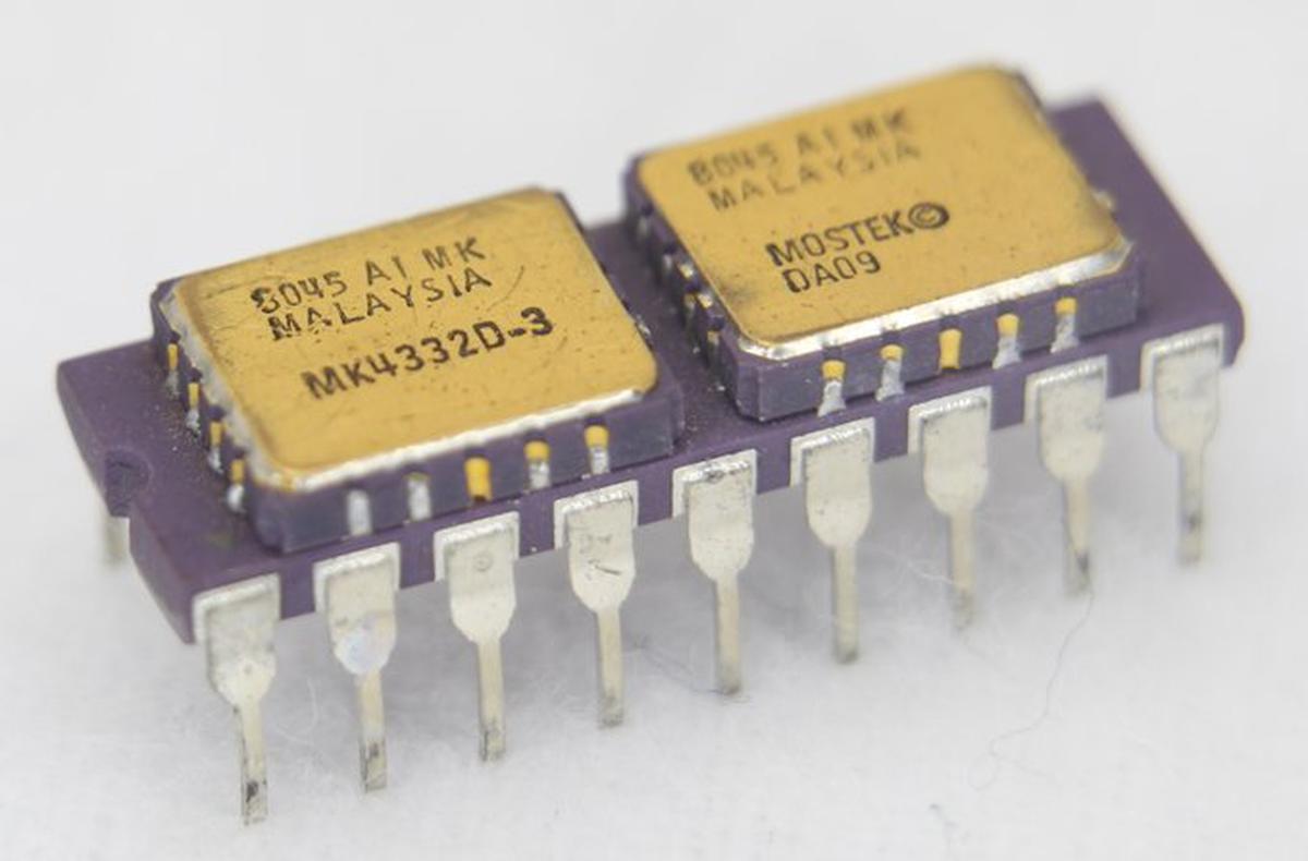
In 1978, a memory chip stored just 16 kilobits of data. To make a 32-kilobit memory chip, Mostek came up with the idea of putting two 16K chips onto a carrier the size of a standard integrated circuit, creating the first memory module, the MK4332 "RAM-pak". This module allowed computer manufacturers to double the density of their memory systems and by 1982, Mostek had sold over 3 million modules. The Apple III is the best-known system that used these memory modules.
This module was built from two 16-kilobit memory chips, constructed from the standard MK4116 dynamic RAM (DRAM) chip packaged in a leadless ceramic chip carrier; these are the golden rectangles on top of the carrier.
You might wonder why customers didn't simply use these surface-mount packages directly, but at the time soldering surface-mount components was still a challenge for many customers. However, mounting two leadless chips on a dual inline-package (DIP) carrier allowed customers to double their memory density while still using their standard through-hole soldering techniques.
The purple carrier holding the chips was a ceramic substrate designed for thermal compatibility with the chips.1 There is no circuitry inside the ceramic carrier except wiring between the chips and the eighteen DIP pins. The two memory chips were wired in parallel except for their two select lines, which were kept separate. This allowed the desired memory chip to be selected. As a result, the MK4332 module has 18 pins, compared to 16 pins for the chips on top. Mostek used the same module design with the next generation of RAM chips, creating a 128-kilobit RAM module (MK4528) from two 64-kilobit RAM chips (MK4564).
Inside the 4116 memory chip
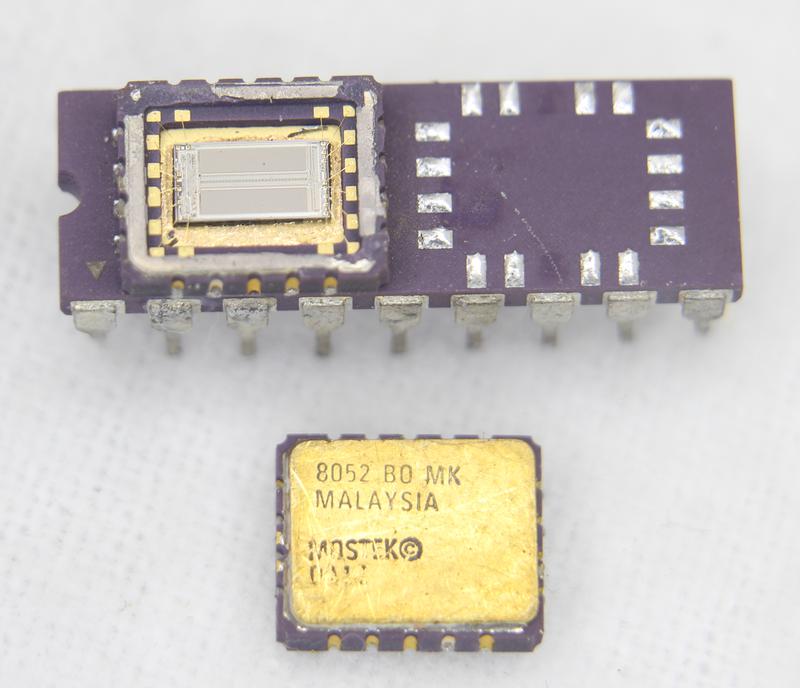
Although you might expect a complex mounting technique, the two 4116 chips are simply soldered onto the substrate with standard reflow techniques. For the photo below, I removed the metal lid from the left chip with a chisel and unsoldered the right chip with a hot air gun. On the left, you can see the rectangular silicon die inside the leadless carrier package. On the right are the 16 solder pads on the ceramic substrate. The wiring between the solder pads and the DIP pins is inside the ceramic substrate.
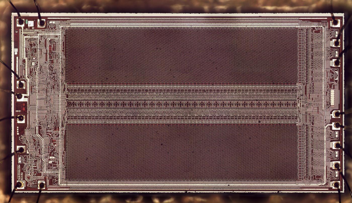
I created the die photo below from multiple microscope images. The white lines are the metal wiring on top of the chip, while the silicon underneath appears dark red. The two large rectangular regions are the 16,384 memory cells, arranged as a 128×128 matrix, split in two. The circuitry in between these regions consists of 128 sense amplifiers to amplify the bits read from memory, and selection circuitry to select one bit out of the 128. (Externally, the chip is accessed as 16,384×1, outputting a single bit. Typically, eight of these chips were used to store bytes.) The control and interface circuitry is at the left and right, connected to the external pads via tiny bond wires.
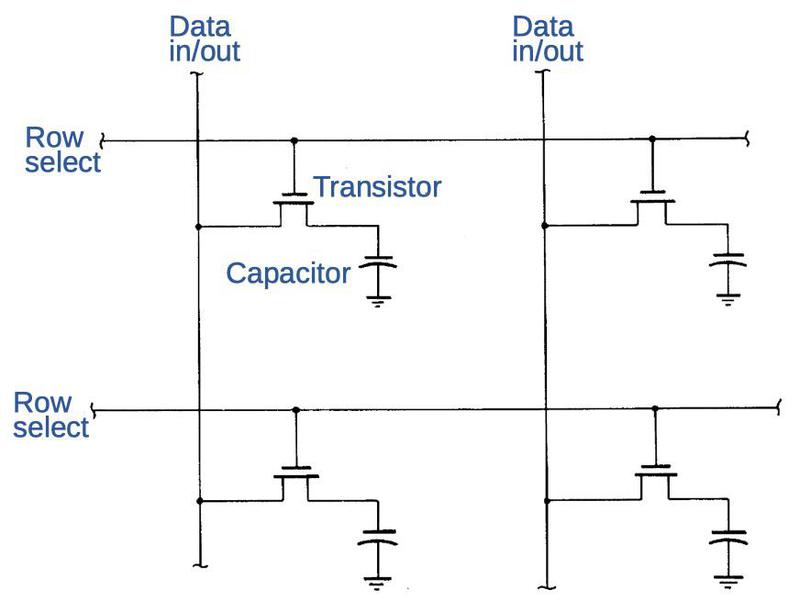
In dynamic RAM, a bit is stored in a capacitor, with a transistor providing access to the capacitor. The value of the bit is represented by the presence or absence of charge on the capacitor. The advantage of dynamic RAM is that each memory cell is very small, constructed from just two components,2 allowing a high memory density. (In comparison, static RAM may require six transistors per cell.) The downside of dynamic RAM is that the charge on a capacitor leaks away after a few milliseconds. To avoid losing data, dynamic RAM must be constantly refreshed: bits are read from the capacitors, amplified, and then written back to the capacitors. For this particular chip, all the data must be refreshed every two milliseconds.
The diagram below illustrates the wiring of the memory cells, showing two of the 128 rows and columns. To read or write data, a row select line is energized. The transistors in that row turn on, connecting that row's capacitors to the data in/out lines. The data from that row is read out of the capacitors and amplified. At that point, the data can either be written back to refresh the row, or a new bit can be written. Note that although the chip accesses 128 bits in parallel internally, the chip provides access to one bit at a time externally, selecting one of the 128 bits to read or write.
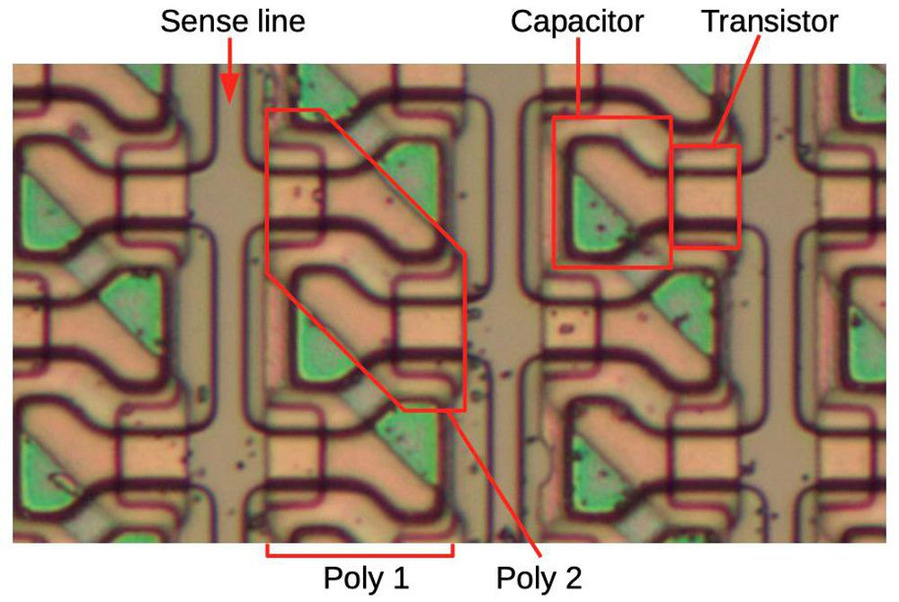
The magnified photo below shows some of the storage cells, densely packed together. It's a bit hard to visualize what's going on because the chip is constructed from multiple layers. The bottom layer is the grayish silicon die. On top of the silicon are two layers of polysilicon. Above this is the metal wiring, which was removed for this photo. The photo shows three sense lines (data in/out) in the silicon, with bulb-shaped storage cells connected on either side. Vertical strips of polysilicon (poly 1) over the storage cells implement capacitors: the silicon forms the lower plate, while the polysilicon forms the upper plate. The second layer of polysilicon (poly 2) is arranged in diagonal regions to implement the selection transistors. Square notches in the poly 1 layer allow the poly 2 layer to approach the silicon to form transistors. Horizontal metal wiring (not visible) is connected to the poly 2 regions to select a row by driving the transistors. Note that the rows are staggered and interlocking (kind of like a zipper) due to the highly-optimized layout. At the time, fitting this much memory on a chip was a challenge that pushed the limits of integrated circuit technology.
Memory chips in the Apple III
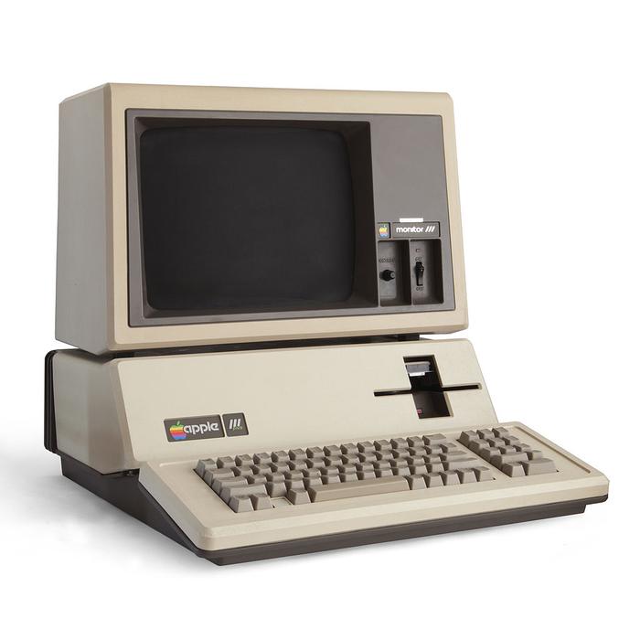
Apple was a major customer of these memory modules, using them in the Apple III computer (1980). The Apple III was marketed as a business computer to follow the popular Apple II. Unfortunately, the Apple III was a business failure due to reliability issues and competition from the IBM PC introduced a year later.
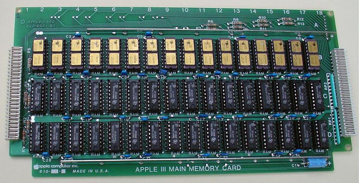
As was usual for the time, the Apple III's memory board3 was stuffed with memory chips to achieve more capacity. An unusual part of the design is it used three rows of memory chips (instead of a power of two), mixing 16-kilobit and 32-kilobit memory chips to achieve 128 kilobytes of storage. (The Apple III's case was designed before the boards, so the boards had to be designed to fit the available space.) In the photo below, the top row holds MK4332 memory modules, while the bottom two rows hold 16-kilobit MK4116 chips.4
A brief history of memory
Memory is an under-appreciated part of computing. The CPU usually gets the attention, but memory was often the limiting factor. The problem with memory is that storing a single bit is easy, but most approaches are impractical when you try to scale up to thousands or millions of bits.
The early ENIAC computer (1946) used vacuum tubes for storage, but these were bulky and expensive, limiting ENIAC to just 20 words (of 10 digits) stored in its accumulators. Early computers such as EDSAC (1949) used mercury delay lines for memory, sending pulse trains of sound waves through tubes of mercury. Although EDSAC could store 512 words, you had to wait for bits to circulate serially through the mercury. An improvement was the random-access Williams tube which stored data as spots on a cathode-ray tube screen. Although they were temperamental, Williams tubes were used in the Manchester Mark 1 (1949) and the commercial IBM 701 (1952).
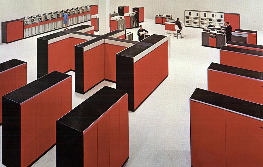
The introduction of core memory revolutionized computing, providing fast, cheap, and reliable storage, storing each bit in a tiny magnetized ferrite ring. Core memory was introduced in the Whirlwind computer (1953) and used in most computers of the late 1950s and 1960s. However, since each bit required a separate physical ferrite core, memory sizes were limited to a few megabytes for even the largest customers. For example, memory cabinets for the IBM System/360 (1969) held 256 kilobytes but weighed over a ton each (below).
Semiconductor memory led to another dramatic shift. At first, semiconductor memory was costly and had very small capacity; Intel's first product was a memory chip holding just 64 bits and costing $99.50. In 1968, Dennard at IBM invented cost-effective dynamic RAM and semiconductor DRAM technology advanced quickly at various companies. Intel introduced the first commercially available DRAM chip in 1970, the i1103 holding 1K bits. This chip was nicknamed the "core killer" because of its impact on the magnetic core memory industry.
Computer storage rapidly moved from core memory to DRAM as the capacity of DRAM increased and the price fell.5 Mostek introduced the 4-kilobit MK4096 chip in 1973, followed by the 16-kilobit MK4116 in 1976. In 1978, Fujitsu introduced the first commercial 64-kilobit DRAM chip and Japan took the lead in DRAM manufacturing.6 Intel left the DRAM industry in 1985 due to decreasing market share and profits, followed by the remaining US DRAM manufacturers.
Fifty years after the introduction of DRAM, it is still the dominant technology for main storage, a remarkably long lifetime. Compared to the 16-kilobit chip I described, Samsung's recent 16-gigabit DRAMs are a factor of a million larger, showing the incredible increase in density. It remains to be seen if anything will challenge the long storage leadership of DRAM.
I announce my latest blog posts on Twitter, so follow me at kenshirriff. I also have an RSS feed. Thanks to Mike Braden for suggesting the MK4332 chip to me.
Notes and references
-
For details on the construction of the memory modules, see Rectangular chip-carriers double memory-board density, Electronics, 1982. ↩
-
Early dynamic RAMs such as the Intel 1103 used three transistors per cell and used separate lines for reading and writing data. Improvements in memory technology shrunk the circuit to a single transistor and a single data line. ↩
-
The Apple III memory board pictured is the "12 volt memory board", given that name because the memory chips required 12 volts (as well as +5 and -5). It was upgraded by the "5 volt memory board", which used only a 5 volt supply. The 5 volt memory board used more modern 64-kilobit memory chips (4864) giving it a larger capacity of 128 or 256 kilobytes. Inconveniently, the power supply required a 12-volt load to operate, so the 5-volt memory board has a power resistor to draw 0.4 amps from the otherwise-unused 12-volt supply. Details are in the Apple III reference manual. ↩
-
The Apple III memory board was also available in a lower-cost 96-kilobyte module. In that configuration, the 4332 memory modules were replaced with the 16-kilobit (MK4116) chips used on the rest of the board. One clever feature of the 4332 module is the two "extra" select pins are on the end of the package. The result is that a memory board (such as the Apple III's) can be designed to accept either the 16-pin 16-kilobyte chips or the 18-pin 32-kilobyte modules, depending on how much memory is desired. With the smaller chips, the two extra pins are unused. It's strange, however, that the Apple III memory board only accepted the larger modules in one of the three rows of chips. ↩
-
The industry switch from magnetic core memory to semiconductor memory wasn't as straightforward as superior semiconductor memory overthrowing inferior core memory. Instead, there was a time period where they co-existed, due to tradeoffs. For instance, in 1972, a customer could select core memory, semiconductor memory, or a mixture for the D-112 minicomputer (a PDP-8 clone); semiconductor memory was 5 times faster, but core memory supplied four times the capacity per board. By 1973, industry publications were reporting that "Semiconductor memories are taking over data-storage applications". As late as 1980, core memory manufacturers were advertising the benefits of core memory, battling the "myths" that semiconductor was better.
Was the overthrow of magnetic core by semiconductor memory inevitable? My view is that "technological determinism" acts in some ways; the development of DRAM memory was almost unavoidable following the development of MOS transistors. However, "economic determinism" was more responsible for the success of semiconductor memory: if magnetic core had remained the lower-cost option, it probably would have remained dominant. As a counterexample, CCD (charge-coupled device) memory and bubble memory were hyped as storage technologies of the future, but couldn't achieve the price-performance to dislodge either semiconductor memory or hard disks. ↩
-
Note that the capacity of memory chips increased by a factor of 4 each generation (1-, 4-, 16-, 64-kilobit) rather than a factor of 2. The reason is that each address pin was multiplexed to provide two address bits, so each additional address pin resulted in a factor of four increase. By reusing each address pin for both a row address and a column address, the number of address pins was kept low so compact 16-pin packages could be used even as memory sizes expanded to 256-kilobit. Conveniently, as technology improved, memory chips required fewer voltages, freeing up pins formerly used for power. One consequence, though, was the ordering of address pins on the chip was essentially random as new address pins were assigned based on which pins were available, rather than sequentially. The multiplexed address system was introduced in the Mostek MK4096 chip and meant that the 256-kilobit 41256 chip used fewer pins than the original 1-kilobit Intel 1103 (16 pins vs 18). ↩
Caption of first picture might be misleading. It says 16 kilobyte and it probably means 16 kilobit.
ReplyDeleteBrian: you are correct; I've updated the caption.
ReplyDeleteGreat article!
ReplyDeleteI think magnetic drum memory also preceded rope-core as a popular primary storage solution for quite awhile.
Offhand, I know the 305 RAMAC used it as a primary buffer.
I know you weren't trying to make a complete history of memory types. But I do think magnetic drums did help "turn" the wheels of progress 😁
Enjoying fond memories of the equally novel 8K x 8 stacked static RAM (4-ICs x 2K x 8, top and bottom on a DIP ceramic block) on the Tandy Model 100. Rather scarce now, of course.
ReplyDeleteYou may want to investigate the next generation of this idea, which was carried out using plastic packaged (i.e. vastly cheaper than ceramic packaged) DRAM chips. These were two 64Kbit DRAMs, also from Mostek, each one housed in an 18 pin DIP ... even though a 64Kx1 only has 16 pins. The two DIPs were vertically stacked and would plug into a standard 18 pin socket, giving you 128K per footprint. There was an official codename but the unofficial one was more memorable: fkkk-bug. Dig around, you'll find photos and perhaps some real live units.
ReplyDeleteFatangaboo
At least one US DRAM manufacturer did not leave the business in the 1980s. Micron was established in 1978 and is still in business.
ReplyDelete