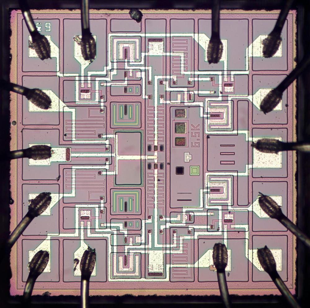
This blog post examines a 1980s chip used in a Soyuz space clock. The microscope photo below shows the tiny silicon die inside the package, with a nice, geometric layout. The silicon appears pinkish or purplish in this photo, while the metal wiring layer on top is white. Around the edge of the chip, the bond wires (black) connect pads on the chip to the chip's pins. The tiny structures on the chip are resistors and transistors.
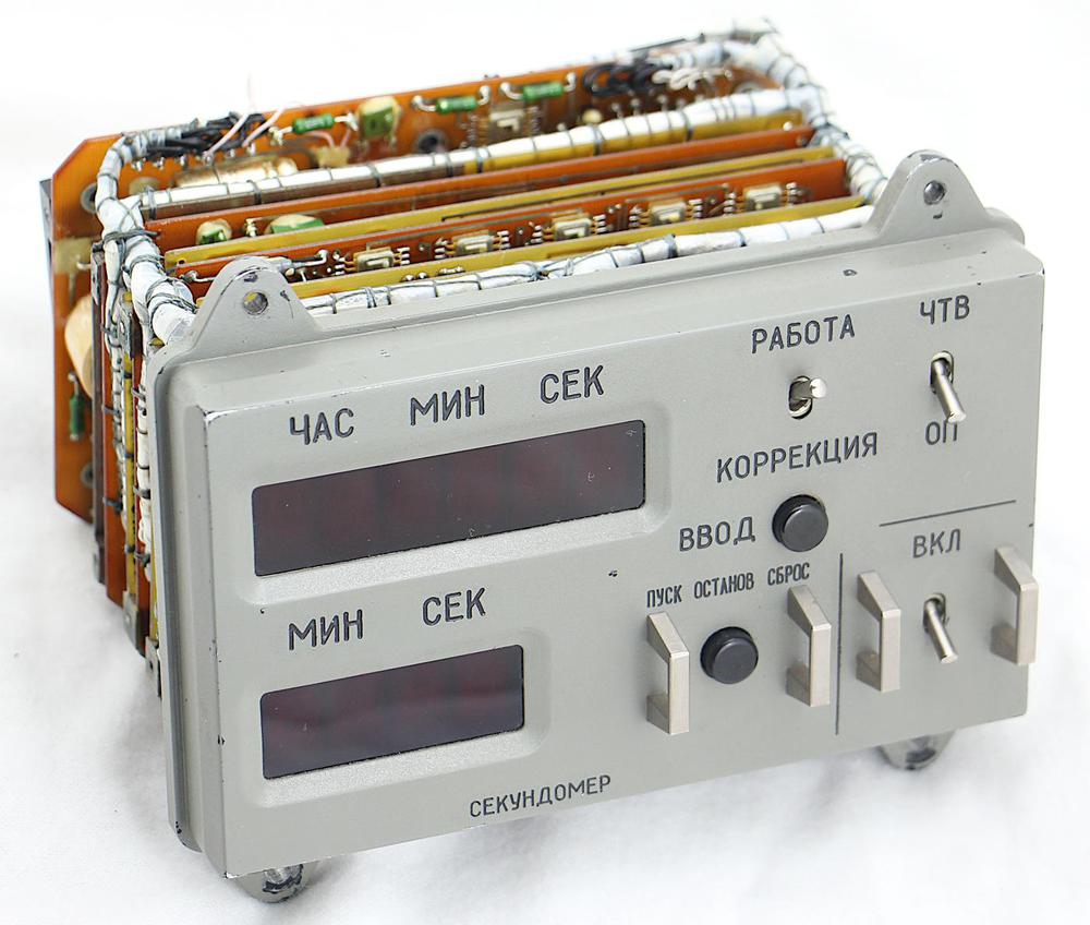
The chip is used in the clock shown below. We recently obtained this digital clock that flew on a Soyuz space mission.1 The clock displays the time on the upper LED digits and provides a stopwatch on the lower LEDs. Its alarm feature activates an external circuit at a preset time. I expected that this clock would have a single clock chip inside, but the clock is surprisingly complicated, with over 100 integrated circuits on ten circuit boards. (See my previous blog post for more information about the clock.)
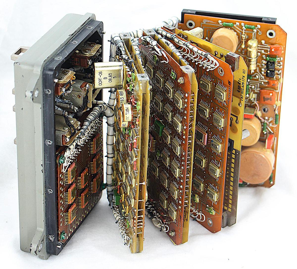
The clock's circuit boards can be opened like a book to reveal the integrated circuits and other components, thanks to the flexible wiring harnesses that connect the boards. The integrated circuits are mostly 14-pin "flat packs" in metal packages, surface-mounted on the printed circuit boards. I wanted to know more about these integrated circuits, so I opened one up,2 took photos, and reverse-engineered the chip's circuitry.
Soviet integrated circuits
The clock is built from TTL integrated circuits, a type of digital logic that was popular in the 1970s through the 1990s because it was reliable, inexpensive, and easy to use. (If you've done hobbyist digital electronics, you probably know the 7400-series of TTL chips.) A basic TTL chip contained just a few logic gates, such as 4 NAND gates or 6 inverters, while a more complex TTL chip implemented a functional unit such as a 4-bit counter. Eventually, TTL lost out to CMOS chips (the chips in modern computers), which use much less power and are much denser.
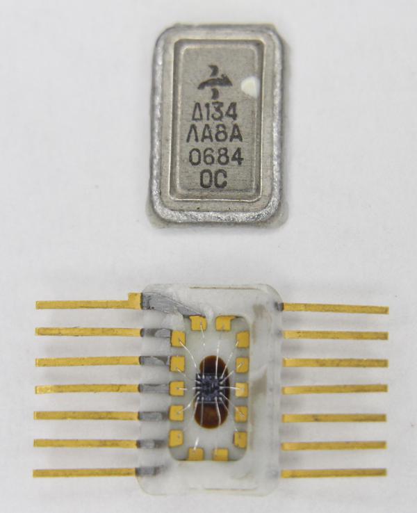
The photo below shows a chip with its metal lid removed. The tiny silicon die is visible in the middle, with bond wires connecting the die to the pins. This integrated circuit is very small; the ceramic package is 9.5mm×6.5mm, considerably smaller than a fingernail. To open up a chip like this, I normally put it in a vise and then tap the seam with a chisel. However, in this case, the chip decapped itself—while I was looking for a hammer, the top suddenly popped off due to the pressure from the vise.
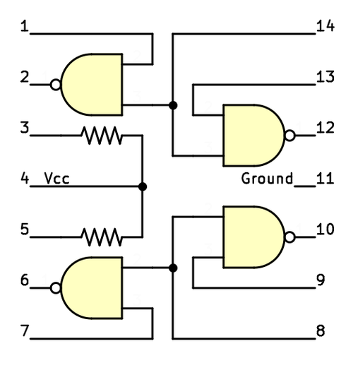
The chip I'm examining has the Cyrillic part number 134ЛА8 (134LA8)6. It implements four open-collector NAND gates, as shown below.4 The NAND gate is a standard logic gate, outputting a 0 if both inputs are 1, and otherwise outputting a 1. An open-collector output is slightly different from a standard output. It will pull the output pin low for a 0, but for a 1 it just leaves the output floating ("high impedance").5 An external pull-up resistor is required to pull the output high for a 1. The clock uses three of these chips: one in the quartz crystal oscillator circuit, and another functioning as inverters in another part of the clock.3
The Soviet Union lagged about 9 years behind the US in integrated circuit development.7 The lag would have been much larger, except the Soviet Union copied many Western integrated circuits. As a result, most of the Soviet TTL chips have Western equivalents.4 However, the 134ЛА8 chip that I examined is different from Western chips8 with two unusual features. First, to reduce the number of external resistors, this chip includes two pull-up resistors on the chip that can be wired up as desired. Second, the chip shares two NAND gate inputs, which frees up the two pins used by the resistors. Thus, even though the Soviet Union was copying integrated circuits, they were also creatively designing their own chips.
Integrated circuit components
Under the microscope, the transistors and resistors of the integrated circuit are visible. The silicon die appears in shades of pink, purple, and green, depending on how different regions of the chip have been "doped". By doping the silicon with impurities, the silicon takes on different semiconductor properties, making N-type and P-type silicon. On top of the silicon, the white lines are metal traces that wire together the components on the silicon layer.
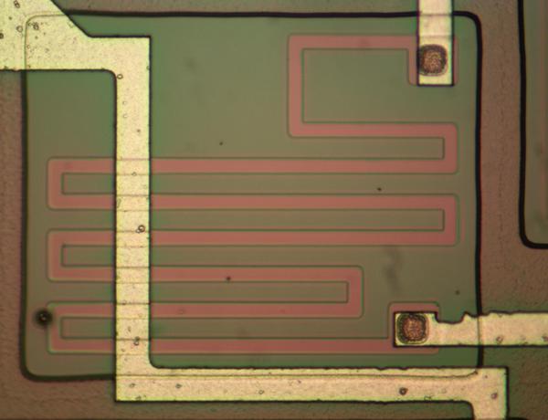
The photo below shows how a resistor appears on the silicon die. A resistor is formed by doping silicon to form a high-resistance path, the reddish line below. The longer the path, the higher the resistance, so the resistors typically zig-zag back and forth to create the desired resistance. The resistor is connected to the metal layer at both ends, while another metal passes over the resistor shown below.
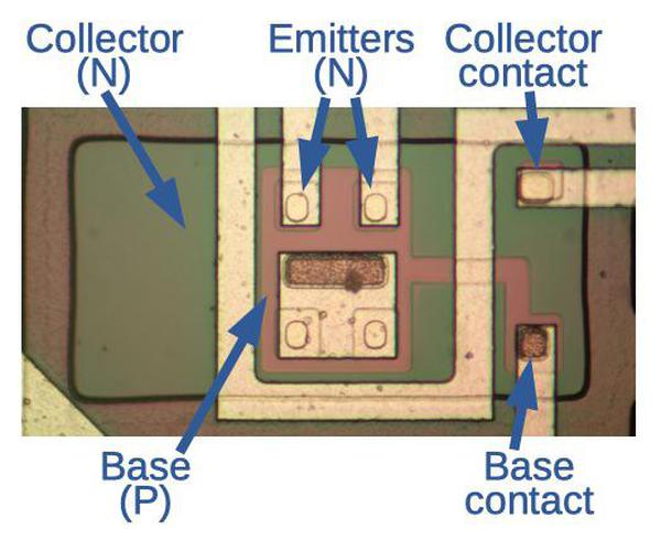
This chip, like other TTL chips, uses bipolar NPN transistors. These transistors have N-type silicon for the emitter, P-type silicon for the base, and N-type silicon for the collector. On the IC, the transistors are constructed by doping the silicon to form layers with different properties. At the bottom of the stack, the collector forms the bulk of the transistor, doped to form N-type silicon (the large green area below). On top of the collector, a thin region of P-type silicon forms the base; this is the reddish region in the middle. Finally, a small square N-type emitter is formed on top of the base. These layers form the N-P-N structure of the transistor. Note that the metal wiring to the collector and base is off to the side, away from the main body of the transistor.
TTL circuits typically used transistors with multiple emitters, one for each input, and this can be seen above. A multiple-emitter transistor may seem strange, but it is straightforward to build one on an integrated circuit. The transistor above has two emitters wired up. Close examination shows there are four emitters, but the two lower unused emitters are shorted to the base.
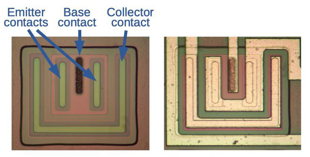
The output transistors on the chip produce the external signal from the chip, so they must support much higher current than the other transistors. As a result, they are much larger than the other transistors. As before, the transistor has a large N-type collector region (green), with a base on top (pink), and then emitter on top of the base. The output transistor has long contacts between the metal layer and the silicon, rather than the small square contacts of the previous transistor. The emitter (wired in a "U" shape) is also much larger. These changes allow more current to flow through the transistor. In the photo below, the transistor on the left has no metal layer, so its silicon features are more visible.9 The transistor on the right shows the metal wiring.
How a TTL NAND gate works
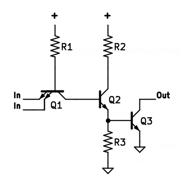
The schematic below shows one of the open-collector NAND gates in the chip. In this paragraph, I'll give a brief explanation of the circuit; you can skip this if you want.10 To understand the circuit, first assume that an input is 0. The current through resistor R1 and the base of transistor Q1 will flow out through the transistor's emitter and the low input. Transistor Q2 will be off, so R3 pulls Q3's base low, turning Q3 off. Thus, the output will float (i.e. open-collector 1 output). On the other hand, suppose both inputs are 1. Now the current through R1 can't pass through an input so it will flow out the collector of Q1 (i.e. backward) and into Q2's base, turning on Q2. Q2 will pull Q3's base high, turning on Q3 and pulling the output low. Thus, the circuit implements a NAND gate, outputting 0 if both inputs are high. Note that Q1 isn't acting like a normal transistor, but instead is "current-steering", directing the current from R1 in one direction or the other.
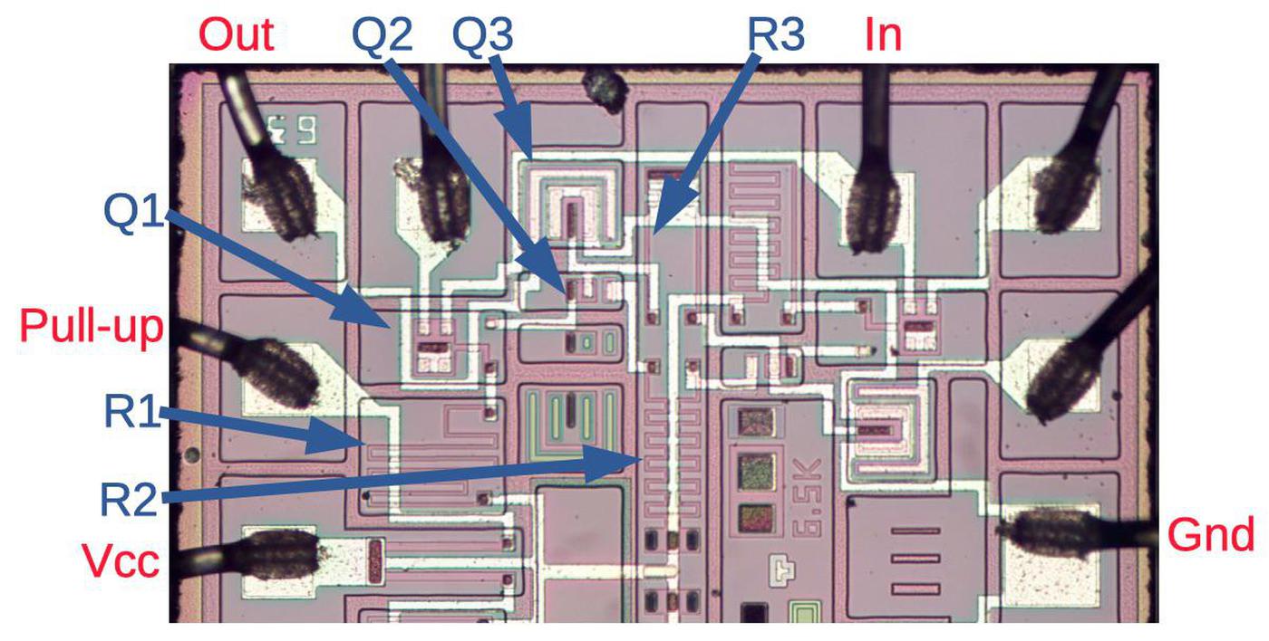
The diagram below shows the components for one of the NAND gates, labeled to match the schematic. (The three other NAND gates on the chip are similar.) The wiring of the gate is simple compared to most integrated circuits; you can follow the metal traces (white) and match up the wiring with the schematic. Note the winding path from the ground pad to Q3. Q1 is a two-emitter transistor while Q3 is a large output transistor. Two unused transistors are below Q2.
Conclusion
This Soviet chip from 1984 is simple enough that the circuitry can be easily traced out, illustrating how a TTL NAND gate is constructed. The downside of simple chips, however, is that the Soyuz clock required over 100 chips to implement basic clock functionality. Even at the time, single chips implemented wristwatches and alarm clocks. Now, modern chips can contain billions of transistors, providing an extraordinary amount of functionality, but making the chip impossible to understand visually.
My previous blog post discussed the clock's circuitry in detail and I plan to write more about the clock, so follow me @kenshirriff (or on RSS) for details. Until then, you can watch CuriousMarc's video showing the disassembly of the space clock:
Notes and References
-
CuriousMarc obtained the clock from an auction and it was advertised as flown to space, but we don't know which mission it was flown on. The date codes on the components inside the clock are mostly from 1983, with one from 1984, so the clock was probably manufactured in 1984. The Russian name for the clock is "Бортовые Часы Космические" (Onboard Space Clock), which is abbreviated as "БЧК". ↩
-
Don't worry; I didn't destroy any of the chips in the clock. We bought duplicate chips on eBay for reverse-engineering. I was surprised that most of these 1980s-era chips are not too hard to obtain. ↩
-
I don't see any obvious reason why the 134ЛА8 chip was used instead of an inverter chip. Surprisingly, even though the 7404 hex inverter chip was extremely common in US designs, the clock doesn't use any inverter chips at all. ↩
-
For more information on Russian integrated circuits, including the ones used in the clock, see the databook Интегральные микросхемы и их зарубежные аналоги (Integrated circuits and their foreign counterparts). (The title makes it explicit that they were copying foreign chips.) Be warned that the databook's description of the 134ЛА8 has a few typos. ↩↩
-
One reason to use open-collector gates is to get an AND gate "for free". Connecting outputs together produces a wired-AND; if any output is a 0, the tied-together output is a 0. (Tying together NAND gates is equivalent to AND-OR-INVERT logic.)
Open-collector outputs can also be used on a bus, where multiple devices or boards can write signals to a bus line (as in the Xerox Alto) without electrical conflict. This use is obsolete, though; tri-state outputs provide much better performance. ↩
-
One nice thing about Russian ICs is that the part numbers are assigned according to a rational system, unlike the essentially random numbering of American integrated circuits. Two letters in the part number indicate the function of the chip, such as a logic gate, counter, flip flop, or decoder. For example, consider the label "Δ134 ЛA8A". The series number, 134, indicates the chip is a low-power TTL chip. The "Л" (L) indicates a logic chip (Логические), with "A" indicating the NAND gate subcategory. Finally, "8" indicates a specific type of NAND chip in the ЛA category. As with American chips, the "0684" date code on the chip indicates that it was made in the 6th week of 1984. ↩
-
Two CIA reports (1974 and 1986) provide information on the lag between Soviet IC technology and Western technology. "Microcomputing in the Soviet Union and Eastern Europe", ABACUS, 1985, discusses how the Soviet Union copied American microprocessors, especially Intel ones. ↩
-
The 7400 series includes several quad open-collector NAND gate chips, such as the 7401, 7403, 7426, 7438, and 7439. These are all different from the Soviet chip. A die photo of the 74S01 is here; I think the Soviet chip has a much nicer layout. ↩
-
The integrated circuit has a few unused transistors. In addition, the input transistors have 4 emitters, but only two of them are used. This is probably so the same silicon die can be used to manufacture multiple integrated circuits by changing the metal layer. For instance, the 4-emitter transistors could be used for 3- or 4-input NAND gates. Alternatively, the unused transistors could be used to create a hex inverter chip. ↩
-
For a detailed explanation of how TTL gates work, see this page. ↩
14 comments:
Any thoughts on why the layout feels so much nicer/cleaner than some of the equivalent American chips implementing similar functionality?
One guess I had is that maybe it was more generic and reconfigurable with just masking than some of the equivalents?
modwizcode: you're probably right that the ability to re-use the layout was a motivation in keeping the design clean. In addition, I suspect that American chip manufacturers had much more pressure to squeeze out extra space to reduce cost. In comparison, the soviet chip has a lot of wasted space.
My first thought on the unused components was that they could use those with some reconfiguration of the "wires" on the die.
Chuck out a lot of the same dies and in the last step(s) you wire it to be a certain type of chip.
Probably saves a ton on machines and makes quality control easier, at the cost of a slightly larger footprint.
Good article to learn electronics, congratulations
I suppose instead of "Thus, the input will float" you wanted to write "Thus, the output will float".
The reason Soviet chip numbers were organized was probably because they started copying already a considerable selection, instead of coming up with numbers as they developed them, like US did.
Wonderful article, as usual. Thanks a lot!
"The longer the path, the higher the resistance, so the resistors typically zig-zag back and forth to create the desired resistance."
This is good enough for this post. It would be a little more correct to say that the higher the ratio of the length to the width, the higher the resistance. So a path that is twice as wide and twice as long would have the same resistance. It would be able to carry twice the current, but would take up roughly four times the area. So if we can get away with it, we want to make all the resistors the minimum width in order to occupy the minimum area. That seems to be the case in this design, so with all resistors the exact same width the length is the only thing that matters.
Hi! This IC is my childhood's toys. I've play a lot with it. :)
To let you know that much IC in the simple clock was used to provide redundancy and fault protection for the device. This is space gear so it just cannot fail due to production defects.
Also these ICs are probably radiation hardened as was used in space at high radiation level.
Great article as usual Ken. One line I would take issue with though:
Note that Q1 isn't acting like a normal transistor, but instead is "current-steering", directing the current from R1 in one direction or the other.
When one of the inputs goes low the transistor will operate in common base mode and actively pull current out of the base of Q2, turning it off faster than would the case if Q1 was replaced with diodes.
As for better numbering of Soviet chips, it's mainly because of planned economy - the state introduced standards which organizations (also state-owned) had to follow. However, there were a lot of chips that broke logical numbering system (it depended on who originaly ordered creation of given chip, I think).
The crystal is very different from the original 7400. Here a special method of isolation of elements is applied. This method is needed for high radiation resistance.
This one is RTL technology. Resistor-Transistor-Logic.
Unknown: no, it is TTL, Transistor Transistor Logic, as I explain in the article.
Yes, you are right. My fault. Looked for wrong part code. This one is the right datasheet: http://www.155la3.ru/datafiles/134la8.pdf
Off-topic joke from those days, you can delete it after reading:
Soviets have everything bigger and faster, for example wristwatch.
About copying chips: Here in eastern europe almost every country produced its own copy of Intel 8080.
And I almost forgot: Great blog! I'm reading it already for three days and I'm not event in a half. Thank you.
Post a Comment