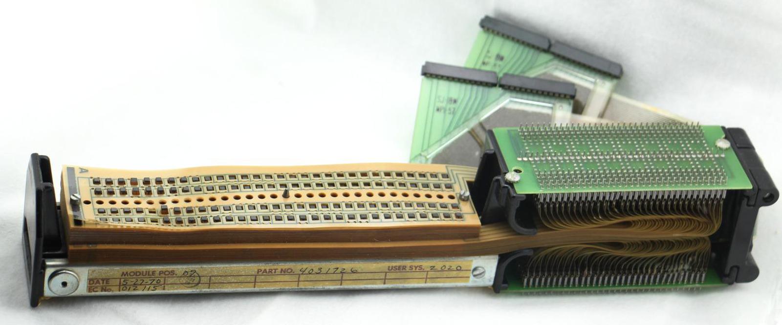
I recently came across a Transformer Read-Only Storage (TROS) module that stored microcode in an IBM System/360 mainframe computer. This unusual storage mechanism used a stack of Mylar sheets to hold 15,360 bits, equivalent to 1920 bytes. By modern standards, this is an absurdly small amount of data, but in 19641, semiconductor read-only memory chips weren't available, so using Mylar sheets for storage was a reasonable solution. In this blog post, I explain how the TROS module worked and its role in the success of the IBM System/360.
How TROS worked: transformers and current pulses
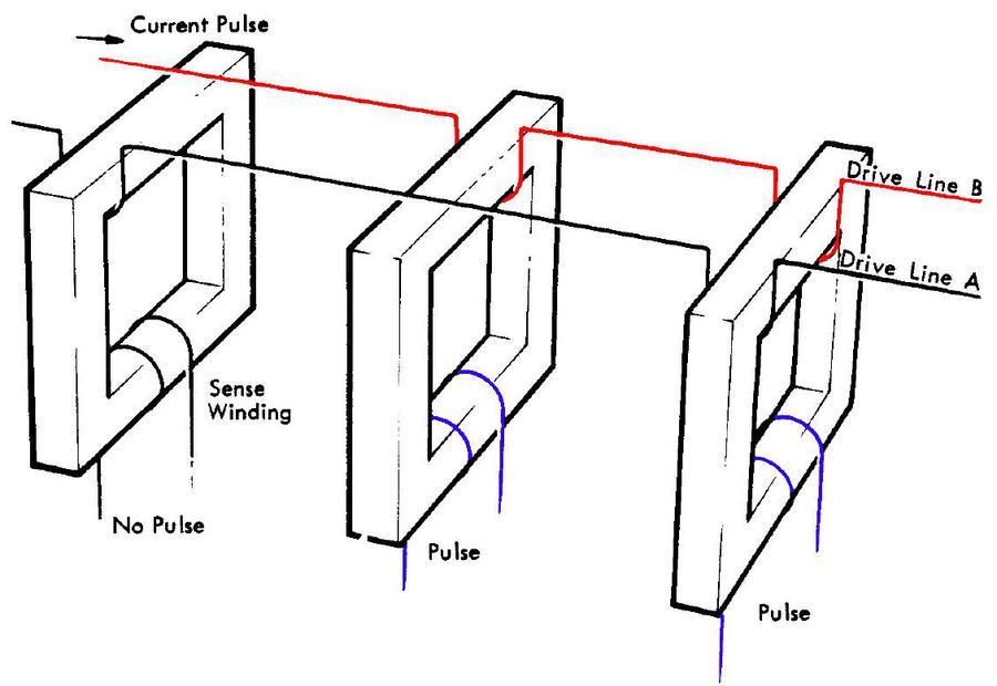
The diagram below shows the concept behind TROS, simplified to two words of three bits each. The three transformers (square rings) each have a sense winding that generates one bit of output. Each word (A or B) has a drive line that passes either through a transformer (for a 1 bit) or around a transformer (for a 0 bit). In the diagram, drive line B (red) is activated by a current pulse. It generates a pulse (blue) from the second and third transformers, generating the bits 011 for Word B. The wiring for Word A, on the other hand, generates the bits 101. Storing more words is accomplished by threading more drive lines through (or around) the transformers, one for each word. Any bit pattern can be stored, depending on how the drive line is wired.
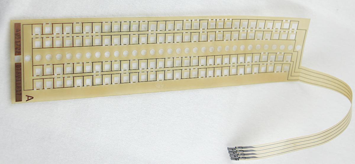
The actual TROS module has 60 transformers and 256 drive lines, so it held 256 words of 60 bits. Physically threading 256 wires through transformers would be difficult, so the TROS module used a clever technique to make the wiring easy to assemble or modify. The wiring was printed on sheets of Mylar (called tapes), essentially a flexible printed circuit board. Each tape had two loops of wiring (called word lines) that either went through or around the transformers, so 128 Mylar tapes provided the wiring for 256 words.
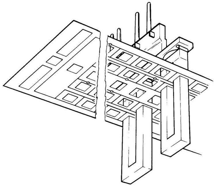
The Mylar tapes were stacked on the 60 transformers as shown below. Each of the 60 transformers consisted of a U-shape with both arms passing through the stack of 128 tapes. In this way, the Mylar tapes efficiently created the wiring through and around the transformers, rather than threading individual wires.
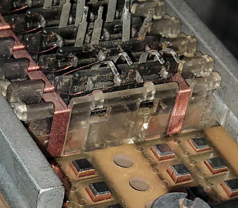
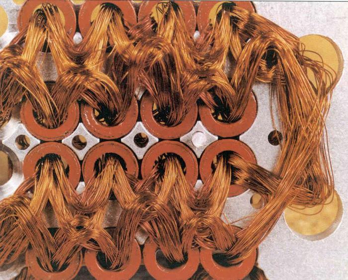
Once the stack was complete, an I-bar was placed on top of each U to close the transformer core. A sense line (the reddish wiring below) was wrapped many times around each I-bar to detect the output signal. Each sense line was connected to a sense amplifier that detected the output signal, to produce the 60-bit output. (The I-bars and sense lines are missing from the TROS module I have but are visible in the module below.)
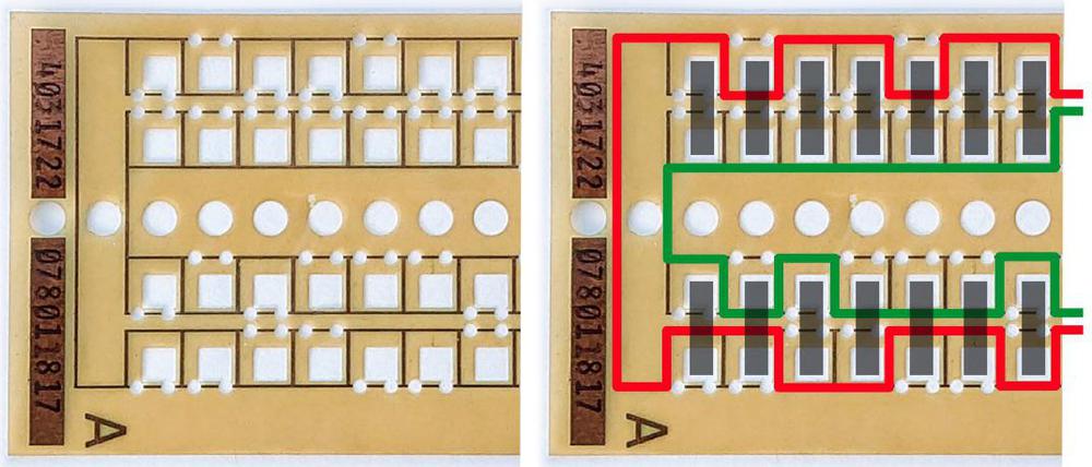
The Mylar tapes were programmed by punching holes through wires to break the undesired wiring paths. The photo below shows a closeup of one of the tapes, showing the wiring printed on the tape, the large square holes for the transformer legs, and the small round holes punched through the word line wiring. The diagram on the right illustrates the wiring path resulting from the hole pattern. Each tape has two word lines (indicated in red and green) that go either through or around each transformer (gray rectangle).
To read one of the 256 words, one word line (wire loop) on one particular Mylar tape received a current pulse. The straightforward implementation would use 256 pulse drivers, with one selected by the address bits, but this much hardware would be expensive. Instead, the TROS module is driven by a "matrix" approach. The 256 word lines are wired logically into a 16×16 matrix. The address is split in half, and each half is decoded to select one of 16 lines. The word line that is selected on both ends line will receive a current pulse and be activated.2
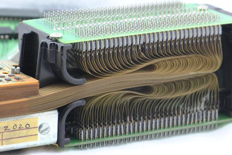
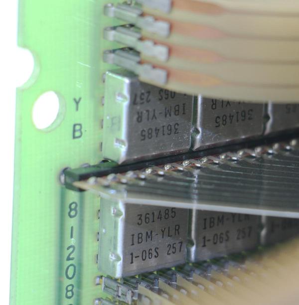
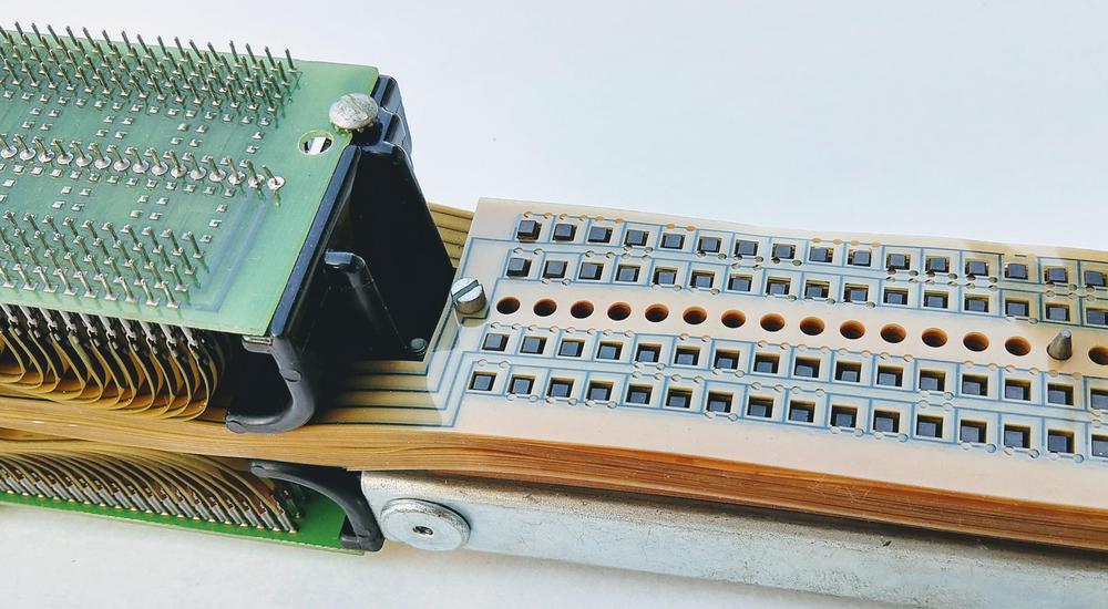
Each Mylar tape is connected to one of two diode boards, resulting in hundreds of connections (above). (These diodes prevent the matrixed signals from all shorting together.) The diodes are inside the square aluminum modules below. The IBM System/360 didn't use integrated circuits, but instead used SLT modules, hybrid modules containing tiny semiconductors and thick film resistors. The SLT modules below each contain 8 diodes.
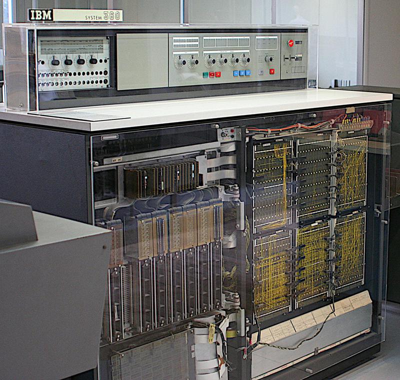
The TROS module I have was used on the low-end System/360 Model 20 computer, according to the label on it. The Model 20 was a slow, stripped-down system, lacking the full System/360 instruction set. Even so, its low cost ($1280 per month) made it the most popular System/360 model. The Model 20 contained 8 TROS modules, holding 6144 micro-instructions (3 micro-instructions per 60-bit word).3 These modules are visible on the left side of the computer below, mounted vertically. Note that the TROS modules take up a lot of space inside the computer.
In case you're wondering what the Model 20 microcode looks like, a sample is below. The microcode itself (in hex) is highlighted in blue, with the mnemonic expansion in green. Comments are on the right. The Model 20's microcode is much simpler than the horizontal microcode in larger System/360 systems.4
Why microcode?
One of the hardest parts of computer design is creating the control logic that tells each part of the processor what to do to carry out each instruction. In 1951, Maurice Wilkes came up with the idea of microcode: instead of building the control logic from complex logic gate circuitry, the control logic could be replaced with code (i.e. microcode) stored in a special memory called a control store. To execute an instruction, the computer internally executes several simpler micro-instructions, which are specified by the microcode. With microcode, building the processor's control logic becomes a programming task instead of a logic design task.
However, in the 1950s, storage technologies weren't fast and inexpensive enough to make microcode practical. It wasn't until the IBM System/360 (1964) that commercial computers made significant use of microcode. Microcode played a key role in the success of the System/360, helping IBM produce a line of computers with the same instruction set architecture but widely different implementations. Microcode also simplified backward compatibility, helping the System/360 support instruction sets of older IBM systems.5
IBM's various read-only storage techniques
IBM used several different read-only storage techniques to store microcode, for a combination of political and technical reasons. TROS was developed at IBM's Hursley site in England. This site started working on microcode because transistors were very expensive in England in the 1950s, and microcode could reduce the number of transistors required. Hursley developed a TROS for the SCAMP6 computer. This was followed by the TROS I've described, used on the System/360 Model 20 and Model 40, as well as the IBM 2841 file control unit.
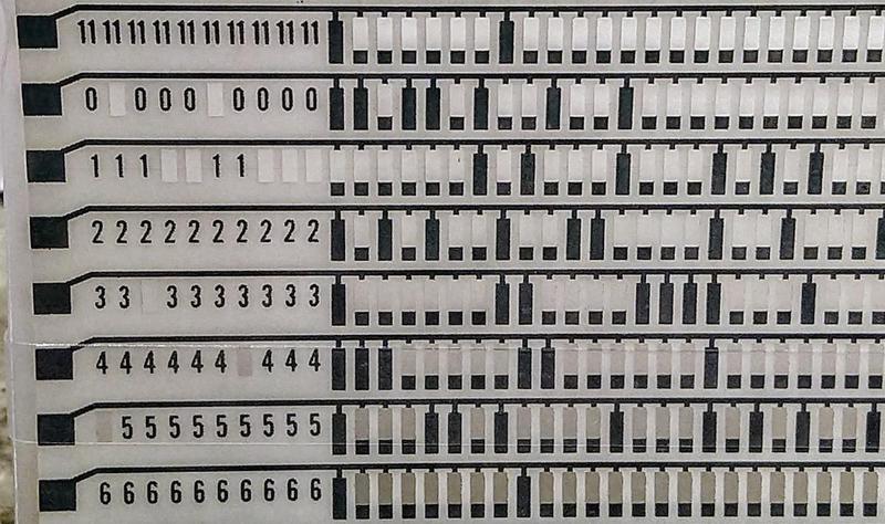
A competing type of read-only storage is CCROS (Capacitive Coupled Read-Only Storage), which used Mylar sheets that functioned as a matrix of capacitors. An interesting feature of CCROS is that the Mylar sheets had the same size as an IBM punch card so microcode could be programmed by punching holes in it with a standard keypunch. CCROS was developed at IBM's Endicott site. Because the System/360 Model 30 was developed there too, it used the locally-developed CCROS even though CCROS was slower and less reliable than TROS. Each CCROS card holds 12 60-bit words. The Model 30 had 42 CCROS boards, each holding 8 cards, for a total of 4032 60-bit words.
The high-performance Models 50, 65 and 67 required a faster control store, so they used a third technology, BCROS (Balanced Capacitor Read-Only Storage). Like CCROS, BCROS read bits by sensing capacitance, but BCROS used two capacitors for each bit (the Balanced Capacitors), which helped reduce noise and increased speed. The Mylar sheets for BCROS were 20″×8½″, much larger than the TROS and CCROS sheets. The data in BCROS was etched into the copper wiring (below), rather than by punching holes. Each bit is represented by two squares: one connected to the upper wire and one connected to the lower wire (or vice versa), forming the balanced capacitors. Each sheet plane held 176 words of 100 bits, and the system used 16 sheets to provide 2816 words.
Instead of using special technology to store microcode, the low-end Model 25 held microcode in a 16-kilobyte section of core memory called Control Storage. In this model, different microcode was loaded from a card deck or tape to switch operating modes between System/360 and emulation of the legacy IBM 1400 series.
An important feature of these storage technologies is that the microcode could be easily updated at customer sites, by swapping the Mylar sheets (or card deck) holding the microcode. Many system bugs could be fixed inexpensively by changing the microcode. (In comparison, an "engineering change" on the older IBM 1401 typically required the engineer to modify wiring on the backplane, much more time-consuming and error-prone.) Microcode could also be upgraded if the customer purchased a new feature.
Comparison with core rope
TROS has some similarities with the core rope storage used by the Apollo Guidance Computer (AGC) to store programs, since both stored read-only data in the pattern of wires through cores. The tradeoffs were different between core rope and TROS. The AGC's core ropes were much more dense than TROS, an important feature for space flight. However, TROS could be easily changed by replacing the plastic tapes, while modifying a core rope required an expensive 8-week manufacturing process to wire up a new module.
TROS and core rope are structurally the opposite, reversing the roles of word (address) lines and sense lines. TROS data depended on which word lines went through or around the transformer, while core rope data depended on which sense lines went through or around a core. To read a word in the AGC, one core was activated, while in TROS all of the transformers were (potentially) activated. Each transformer in TROS had one sense line and was associated with one output bit. In contrast, each core in the AGC's core rope had 192 sense lines and was associated with 12 words. (I've written more on core rope here).
Conclusion
TROS and other read-only storage technologies were a key ingredient in the overwhelming success of the IBM System/360 because they made microcode practical. However, the arrival of cheap semiconductor ROMs in the 1970s obsoleted complex storage technologies such as TROS. Nowadays, most microprocessors still use microcode, but it's stored in ROM inside the chip instead of in sheets of Mylar. Microcode can now be patched by downloading a file, rather than replacing Mylar sheets inside the computer.7
I announce my latest blog posts on Twitter, so follow me @kenshirriff for future articles. I also have an RSS feed.
Notes and References
-
The IBM System/360 was introduced in 1964. The date on this specific TROS module is May 27, 1970. ↩
-
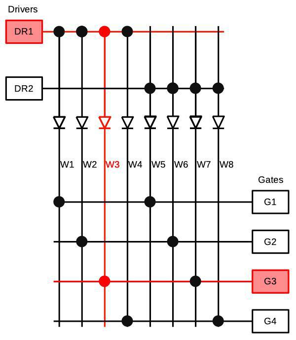
The diagram below illustrates how the matrix selection and diodes work. This diagram has been simplified to 2 drivers, 4 gates, and 8 word lines; the real system has 16 drivers, 16 gates, and 256 word lines. (What IBM calls a "gate" here is not a logic gate, but a current sink forming the other end of the circuit.) By energizing a particular driver and gate pair, a word line is selected. For instance, if driver 1 and gate 3 are energized, word line 3 is selected, as shown in red. Note that without the diodes, signals could go backward, incorrectly energizing multiple word lines.
Matrix selection of a word line. Energizing driver DR1 and gate G3 selects word line W3. Based on Model 40 Functional Units, p61. -
The Model 20 used 22-bit microcode words, so how did this work with 60-bit TROS? The trick was that some microcode words were truncated to 16 bits, so each TROS word held three microcode words: two 22-bit words, and one 16-bit word. In the Model 20's microcode, each word contained the address of the next microinstruction to execute. Since the truncated 16-bit word could only branch to a limited subset of next microinstructions. Thus, the microcode assembler had to carefully arrange the microcode so micro-instructions requiring a longer branch were stored in one of the longer 22-bit words. ↩
-
A 90-bit micro-instruction in the Model 50 could perform half a dozen different functions in parallel. For example, each yellow box below is a single micro-instructions that is part of floating-point multiplications. Each line in the box is a separate action; the micro-instruction can control the emitter, adder, shifter, mover, and local storage in parallel. The point is that the Model 50 was faster (in part) because it had multiple functional units, and the microcode needed to be much more complicated to control them.
Two micro-instructions (in yellow) in the System/360 Model 50. This is part of the microcode to handle exponent underflow and overflow during floating-point multiplication. The black lines show control flow. The text outside the box is comments. From Model 50 diagram QG702 -
Most System/360 computers used microcode because it reduced cost, increased flexibility, and made development faster. IBM imposed a rule that System/360 computers had to be implemented in microcode unless there was a very good reason not to. The fastest models used hardwired control circuitry, though, to maximize performance. ↩
-
Confusingly, IBM had two unrelated computers called SCAMP. The one using TROS is the Scientific Computer and Modulator Processor, a small computer developed at IBM Hursley for scientific applications, not the better-known prototype for the portable IBM 5100 (Special Computer APL Machine Portable). ↩
-
Modern x86 chips have hardcoded microcode, along with some SRAM that holds microcode patches to fix processor flaws. The patches are downloaded into the processor by the BIOS (details) after each power-on. ↩


Have you seen IBM's patent 3,400,371? http://www.freepatentsonline.com/3400371.html It describes the 360 very precisely (without calling it by that name; you can recognize it by terminology as Channel Command Word, RR, RX, RI etc instruction format, etc). It describes all macro and micro instructions (microcoding is a main claim) and has full schematics too. There are also illustrations of microcode flow similar to the one you show in the article.
ReplyDeleteI used to have a hardcopy of the UK version of this. The layout is very different, but at a glance the contents are pretty much the same.
Rhialto, thanks for the link to the patent. That's an insanely detailed patent (964 pages) including schematics and microcode listing. After studying it closely, this patent is for the S/360 Model 30.
ReplyDeleteLots of data in
ReplyDeletehttps://www.goodreads.com/book/show/1454218.IBM_s_360_and_Early_370_Systems?from_search=true&qid=tFnxSweBtR&rank=1
Related also
https://www.goodreads.com/book/show/15272909-memories-that-shaped-an-industry?from_search=true&qid=tFnxSweBtR&rank=3
Unknown: yes, those are both very good books for anyone interested in the IBM System/360, and I agree with your recommendation.
ReplyDeleteIn the most USSR "clones" of S/360 microcode was used too, but almost only horizontal. For example, the lowest model ЕС-1020 had 64-bit microinstruction. An interesting exception was ЕС-1035 which used 32-bit microinstructions stored in special control RAM; they were something middle between horizontal and vertical-coded.
ReplyDeleteHi Ken,
ReplyDeleteThank you for explaining something I was trying to find out about our newly acquired 360/20 which we have started restoring. You can see pictures of the system with the TROS modules in this blog article https://ibms360.co.uk/?p=666
We have many years ahead of us but are looking for any manuals in electronic form not found on bitsavers for the model 20 if you or any other readers can help. We do have a large set of manuals with it but scanning is going to take a long time.
It's not clear to me how this is all that different from core memory. I suspect same principles, just a variation in the packaging, likely to make manufacturing easier/cheaper?
ReplyDeleteCore memory although kept its memory storage when powered off, but not permanent eventually some cores would lose there state . The Tros magnets do not change states as with core and also speed.
ReplyDeleteIn 1970 our IBM FE "repaired" a failing BCROS microcode memory on a 360/67 using Saran Wrap from a local supermarket. I guess he did this under the guidance of the IBM Kingston plant as a temporary fix to get us back on the air. I had a couple of late night visits to the Kingston plant running tests and benchmarks of our "proprietary OS" on high-end 360/370 models that were just coming into production. Impressive to see rows and rows of (extremely costly) machines in assembly... somewhat reminiscent is WW2 shots of aircraft production facilities (and we know where they all ended up). I wonder what became of IBM machines which were decommissioned... I hope some stayed as museum items rather than sent to the "skip". Technology and engineering achievements to be remembered. I worked on the Ferranti ATLAS (1967 - only 3 built) and had a few "ferrite combs" of microcode store and manuals until the late 80s when they sadly were binned during an office relocate.
ReplyDelete