What explains the popularity of terminals with 80×24 and 80×25 displays? A recent blog post "80x25" motivated me to investigate this. The source of 80-column lines is clearly punch cards, as commonly claimed. But why 24 or 25 lines? There are many theories, but I found a simple answer: IBM, in particular its dominance of the terminal market. In 1971, IBM introduced a terminal with an 80×24 display (the 3270) and it soon became the best-selling terminal, forcing competing terminals to match its 80×24 size. The display for the IBM PC added one more line to its screen, making the 80×25 size standard in the PC world. The impact of these systems remains decades later: 80-character lines are still a standard, along with both 80×24 and 80×25 terminal windows.
In this blog post, I'll discuss this history in detail, including some other systems that played key roles. The CRT terminal market essentially started with the IBM 2260 Display Station in 1965, built from curious technologies such as sonic delay lines. This led to the popular IBM 3270 display and then widespread, inexpensive terminals such as the DEC VT100. In 1981, IBM released a microcomputer called the DataMaster. While the DataMaster is mostly forgotten, it strongly influenced the IBM PC, including the display. This post also studies reports on the terminal market from the 1970s and 1980s; these make it clear that market forces, not technological forces, led to the popularity of various display sizes.
Some theories about the 80×24 and 80×25 sizes
Arguments about terminal sizes go back decades,5 but the article 80x25 presented a detailed and interesting theory. To summarize, it argued that the 80×25 display was used because it was compatible with IBM's 80-column punch cards,1 fits nicely on a TV screen with a 4:3 aspect ratio, and just fit into 2K of RAM. This led to the 80×25 size on terminals such as the DEC VT100 terminal (1978). The VT100's massive popularity led to it becoming a standard, leading to the ubiquity of 80×25 terminals. At least that's the theory.
It's true that 80-column displays were motivated by punch cards4 and the VT100 became a standard,2 but the rest of this theory falls apart. The biggest problem with this theory is the VT100's display was 80×24, not 80×25.3 In addition, the VT100 used extra bytes of storage for each line, so the display memory did not fit into 2K. Finally, up until the 1980s, most displays were 80×24, not 80×25.
Other theories have been expressed on Software Engineering StackExchange and Retrocomputing StackExchange, arguing that 80×24 terminals resulted from technical reasons such as TV scan rates, aspect ratios, memory sizes, typography, the history of typewriters, and so forth. There is a fundamental problem with theories that 80×24 is an inevitable consequence of technology, though: terminals in the mid-1970s had dozens of diverse screen sizes such as 31×11, 42×24, 50×20, 52×48, 81×38, 100×50, and 133×64.11 This makes it clear that technological limitations didn't force terminals into a particular size. To the contrary, as technology improved, most of these sizes disappeared and terminals were largely 80×24 by the early 1980s. This illustrates that standardization was the key factor, not the technology.
I'll briefly summarize why technical factors don't have much impact on the terminal size. Although US televisions used 525 scan lines and 60 Hz refresh,9 40% of terminals used other values.6 The display frequency and bandwidth didn't motivate a particular display size because terminals generated characters with a wide variety of matrix sizes.8 Although memory cost was significant, DRAM chip sizes quadrupled every three years, making memory only a temporary constraint. The screen's aspect ratio wasn't a big factor because the text's aspect ratio often didn't match the screen's ratio.7 Of course technology had some influence, but it didn't stop early manufacturers from creating terminal sizes ranging from 32×8 to 133×64.
The rise of CRT terminals
At this point, a bit of history of CRT terminals will help.11
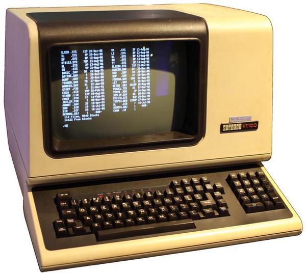
Many readers will be familiar with ASCII terminals, such as stand-alone terminals like the DEC VT100,
serial terminal connections via a PC, or the serial port on boards such as the Arduino.
This type of terminal has its roots in teleprinters, electro-mechanical
keyboard/printers that date back to the early 1900s.
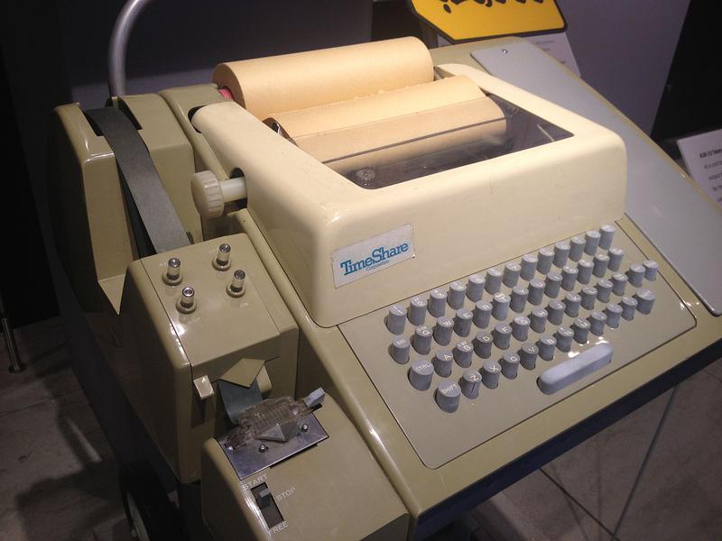
The best-known teleprinter is the Teletype, popular in newsrooms as well as computer systems in the 1970s.
(The Linux device /dev/tty is named after the Teletype.)
Teletypes typically printed 72-character lines on a roll of paper.10
In the 1970s, replacing teleprinters with CRT terminals was a large and profitable market. AT&T introduced the Teletype Model 40 in 1973, a CRT terminal with an 80×24 display.12 Many other companies introduced competing CRT terminals, and "Teletype-compatible" became a market segment. By 198111 these terminals were being used in many roles besides replacing teleprinters and the name shifted to "ASCII terminals". By 1985, CRT terminals were a huge success with 10 million terminals installed in the US.
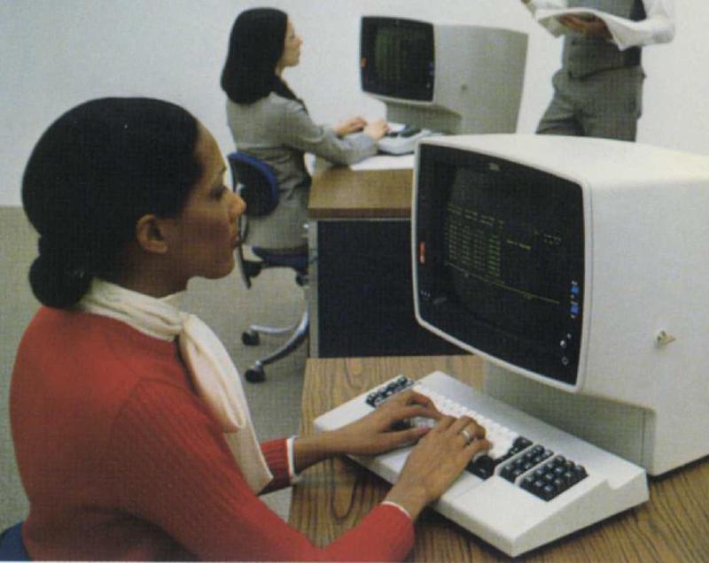
But there's a parallel world of mainframe terminals, a world that may be unfamiliar to many readers. In 1965, IBM introduced the IBM 2260 Display Terminal, which placed IBM's "stamp of approval" on the CRT terminal, which had previously been "somewhat of a novelty."6 This terminal dominated the market until IBM replaced it with the cheaper and more advanced IBM 3270 terminal in 1971. Unlike asynchronous ASCII terminals that transmitted individual keystrokes, these terminals were block oriented, efficiently exchanging large blocks of characters with a mainframe. The 3270 terminal was fairly "intelligent": a 3270 user could fill in labeled fields on the screen, and then transmit all the data at once by pressing the "Enter" key. (This is why modern keyboards often still have the "Enter" key.) Sending a block of data was more efficient than sending each keystroke to the computer, and allowed mainframes to support hundreds of terminals. In the next sections, I'll discuss the 2260 and 3270 terminals in detail.
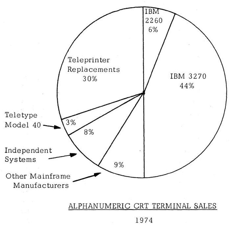
The chart below6 shows how the terminal market looked in 1974. The market was ruled by IBM's 3270 terminal, which had obsoleted IBM's 2260 terminal by this point. With 50% of the market, IBM essentially defined the characteristics of a CRT terminal. Teleprinter replacement was a large and influential market; the Teletype Model 40 was small but growing in importance. Although DEC would soon be a major player, it was in the small "Independent Systems" slice at this point.
The IBM 2260 video display terminal
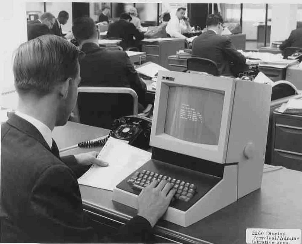
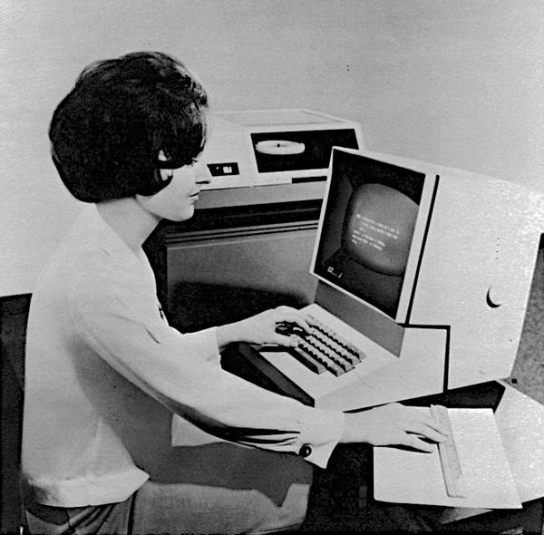
The IBM 2260 was introduced in 1965 and was one of the first video display terminals.14 It filled three roles: remote data entry (in place of punching cards), inquiry (e.g. looking up records in a database), and as a system console. This compact terminal weighed 45 pounds and was sized to fit on a standard office typewriter stand. Note the thickness of the keyboard; it reused the complex keyboard mechanism of the IBM keypunch.13
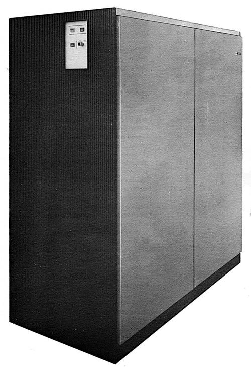
You might wonder how IBM could produce such a compact terminal with 1965 technology. The trick was that the terminal held just the keyboard and CRT display; all the control logic, character generation, storage, and interfacing was in a massive 1000 pound cabinet (below).15 This cabinet contained the circuitry to handle up to 24 display terminals. It generated the pixels for these terminals and send video signals to the terminals, which could be up to 2000 feet away.
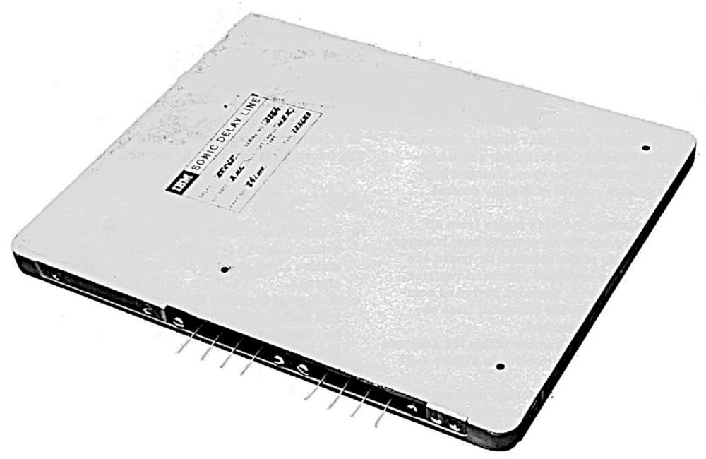
One of the most interesting features of the 2260 is the sonic delay lines used for pixel storage. Bits were stored as sound pulses sent into a nickel wire, about 50 feet long. The pulses traveled through the wire and came out the other end exactly 5.5545 milliseconds later. By sending a pulse (or not sending a pulse for a 0) every 500 nanoseconds, the wire held 11,008 bits. A pair of wires created a buffer that held the pixels for 480 characters.16
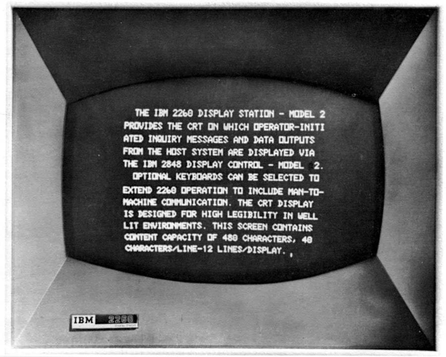
The image below shows the screen of the 2260 Model 2, with 12 lines of 40 characters. (The Model 1 had 6 lines of 40 characters and the Model 3 had 12 lines of 80 characters.) Notice that the lines are double-spaced; this is because the control unit actually generated 24 lines of text but alternating lines went to two different terminals.20 This is a very strange approach, but it split the high cost of the control hardware across two terminals.19 Another strange characteristic was that the 2260's scan lines were vertical, unlike the horizontal scan lines in almost every video display and television.21
Each character was represented in 6-bit EBCDIC, giving a character set of 64 characters (no lower-case). 18 The delay lines stored the pixels to be displayed, but they also stored the EBCDIC code for each character. The trick here is the blank column of pixels between each character for horizontal spacing between characters. The system used this column to store the BCD character value but blanked the display during this column so the BCD value didn't show up as pixels on the screen. This allowed the 6-bit character value to be stored essentially for free.
The relevant question is why did the 2260 have a display with 12 lines of 80 characters?2324 The 80-character width allowed the terminals to take the place of 80-column punch cards for data entry. (In the 40-character models, a card would be split across two lines.) As for the 12 lines, that appears to be what the delay lines could support without flicker.22
The IBM 2260 was a big success, and led to the popularity of the CRT terminal. The impact of the IBM 2260 terminal is shown by a 1974 report on terminals; about 50 terminals were listed as compatible with the IBM 2260. The IBM 2260 didn't have an 80×24 display (although it generated 80×24 internally), but its 40×12 and 80×12 displays made 80×24 the next step for IBM.
The IBM 3270 video display
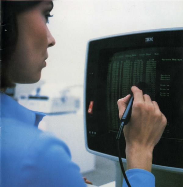
In 1971, IBM released the IBM 3270 video display system, which proceeded to dominate the market for CRT terminals.26 This terminal supported a 40×12 display to provide a migration path from the 2260, but also supported a larger 80×24 display. The 3270 had more features than the 2260, such as protected fields on the screen, more efficient communication modes, and variable-intensity text. It was also significantly cheaper than the 2260, ensuring its popularity.25
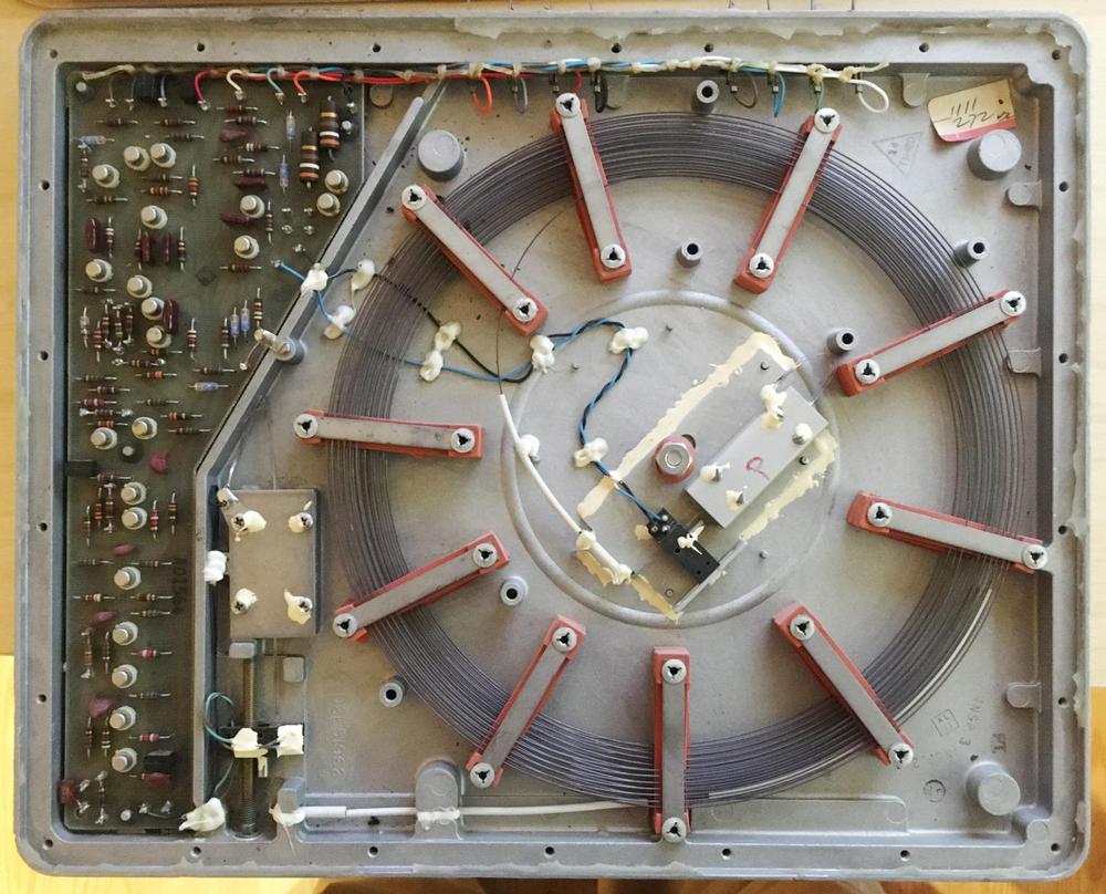
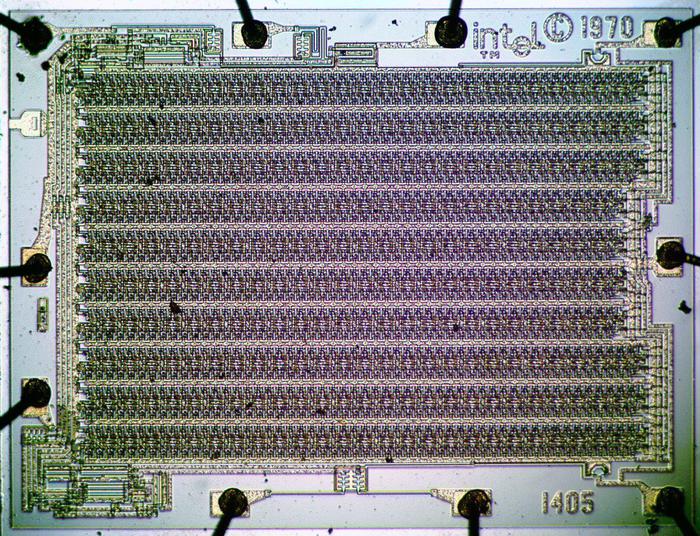
The technology in the 3270 was a generation more advanced than the 2260, replacing vacuum tubes and transistors with hybrid SLT modules, similar to integrated circuits. Instead of sonic delay lines, it used 480-bit MOS shift registers.27 The 40×12 model used one bank of shift registers to store 480 characters. In the larger model, four banks of shift registers (1920 characters) supported an 80×24 display. In other words, the 3270's storage was in 480-character blocks for compatibility with the 2260, and using four blocks resulted in the 80×24 display. (Unlike RAM chips, a shift register size didn't need to be a power of 2. While a RAM chip is arranged as a matrix, a shift register has a serpentine layout (below) and can be an arbitrary size.)
IBM provided extensive software support for the 3270 terminal.28 This had an important impact on the terminal market, since it forced other manufacturers to build compatible terminals if they wanted to compete. In particular, this made 3270-compatibility and the 80×24 display into a de facto standard. In 1977, IBM introduced the 3278, an improved 3270 terminal that supported 12, 24, 32, or 43 lines of data. It also added a status line, called the "operator information area". The new 32- and 43-line sizes didn't really catch on, but the status line became a common feature on competing terminals.
Looking at industry reports61132 shows the popularity of various terminal sizes from the 1970s to the 1990s. Although there were 80×25 displays in 1970 (if not earlier), the 80×24 display was much more common. The wide variety of terminal sizes in 1974 diminished over time, with the market converging on 80×24. By 1979, the DEC VT100 (with its 80×24 display) was the most popular ASCII terminal with over 1 million sold. Terminals started supporting 132×24 for compatibility with 132-character line printers,29 especially as larger 15" monitors became more affordable, but 80×24 remained the most popular size. Even by 1991, 80×25 remained relatively uncommon.
The IBM PC and the popularity of 80×25
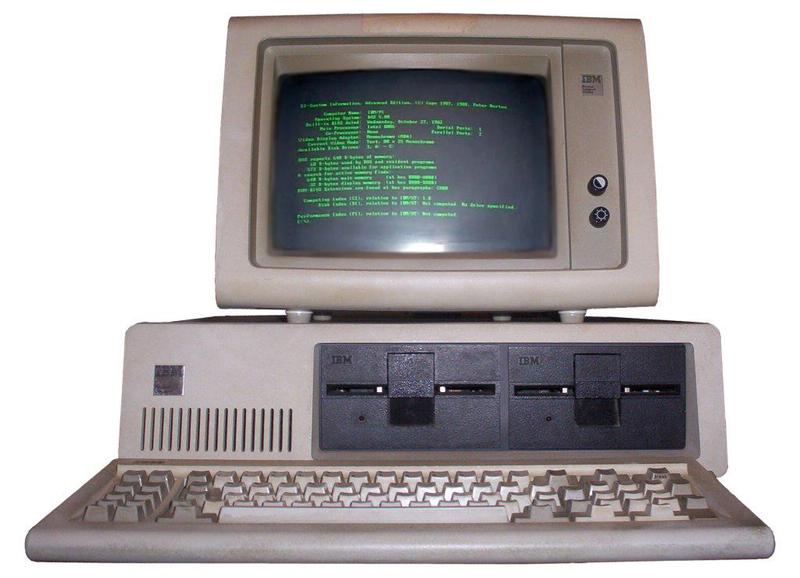
Given the historical popularity of 80×24 terminals, why do so many modern systems use 80×25 windows? That's also due to IBM: the 80×25 display became popular with the introduction of the IBM PC in 1981. The PC's default display card (MDA) provided 80×25 monochrome text while the CGA card provided 40×25 and 80×25 in color. This became the default size of a Windows console, as well as the typical size for PC-based terminal windows.
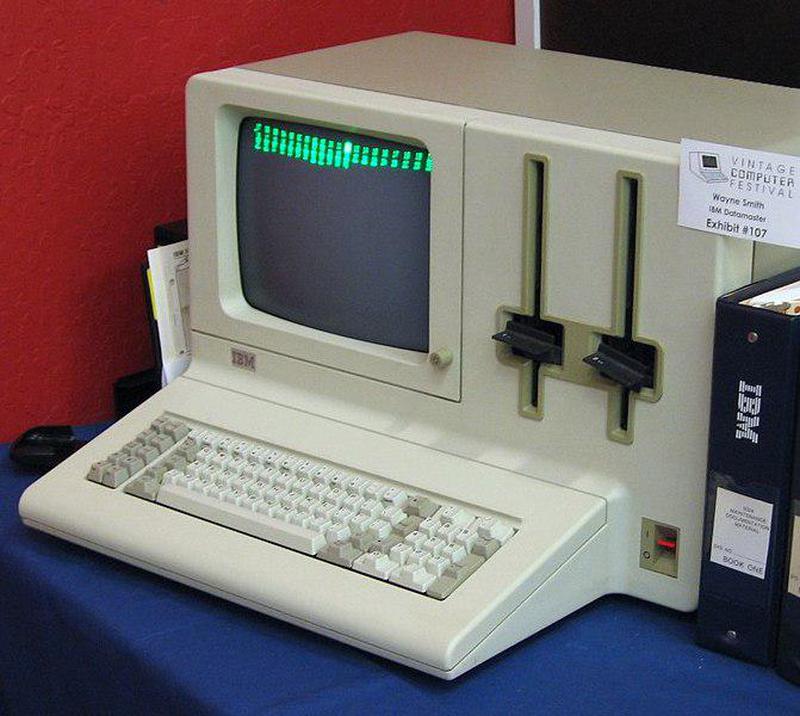
Other popular computers at the time used 24 lines, such as the Osborne 1 and Apple II, so I was curious why the IBM PC used 25 lines. To find out, I talked to Dr. Dave Bradley and Prof. Mark Dean, two of the original IBM PC engineers. They explained that the IBM PC was a follow-on to the rather obscure IBM DataMaster office computer,30 and many of the IBM PC design choices followed the DataMaster microcomputer. The IBM PC kept the DataMaster's keyboard, but detached from the main unit. Both systems used BASIC, but the decision to get the PC's BASIC interpreter from the tiny company Microsoft would change both companies more than anyone could imagine. Both systems went with an Intel processor, an 8-bit 8085 in the DataMaster and the 16-bit 8088 in the IBM PC. They also used the same interrupt controller, parallel port, and timer chips, and almost the same DMA controller. The PC's 62-pin expansion bus was almost identical to DataMaster's.
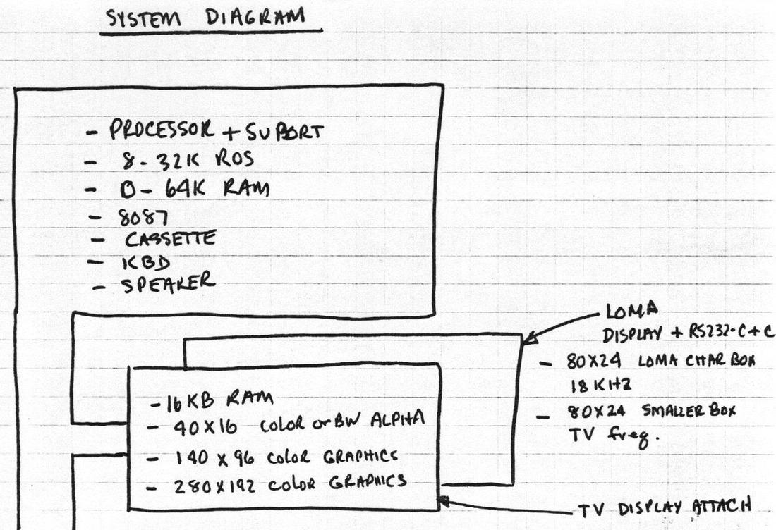
The drawing below is part of an early design plan for the IBM PC. In particular, the IBM PC was going to use the 80×24 display of the DataMaster (codenamed LOMA), as well as 40×16 and 60×16 more suitable for televisions. The drawings also show color graphics with 280×192 pixels, the same resolution as the Apple II. But the IBM PC ended up not quite matching this plan.
The designers of the IBM PC managed to squeeze a few more pixels onto the display to get 320×200 pixels. When using an 8×8 character matrix, the updated graphics mode supported 40×25 text, while the double-resolution graphics mode with 640×200 pixels supported 80×25 text. The monochrome graphics card (MDA) matched this 80×25 size. In other words, the IBM PC ended up using 80×25 text because the display provided enough pixels, and it provided differentiation from other systems, but there wasn't an overriding motivation. In particular, the designers of the PC weren't constrained by compatibility with other IBM systems.31
Conclusion
To summarize, many theories have been proposed giving technical reasons why 80×24 (or 80×25) is the natural size for a display. I think the wide variety of display sizes in the early 1970s proves this technological motivation is mostly wrong. Instead, display sizes converged on what IBM produced, first with the punch card, then the IBM 2260 terminal, the IBM 3270, and finally the IBM PC. The 72-column Teletype had some influence on terminal sizes at first, but this size was also swept away by IBM compatibility. The result is the current situation with an uneasy split between 80×24 and 80×25 standards.
Thanks to Dr. Dave Bradley, Prof. Mark Dean, and IBM engineer Iggy Menendez for information. I announce my latest blog posts on Twitter, so follow me @kenshirriff for future articles. I also have an RSS feed.
Notes and References
-
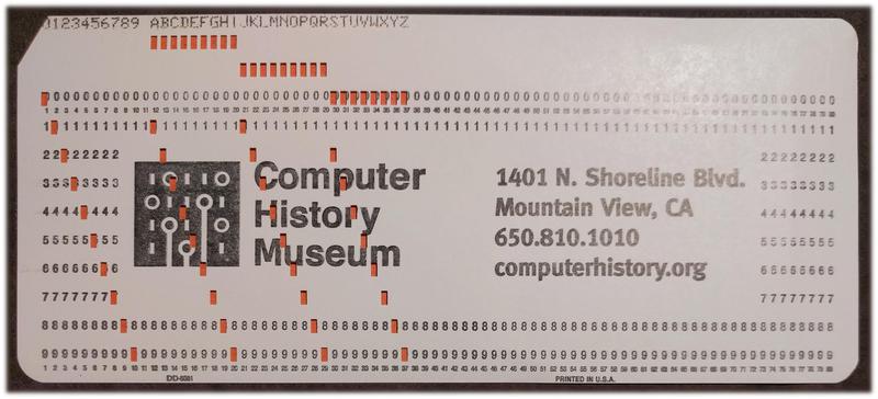
Punch cards have a longer history than you might think. The standard 80-column IBM punch card was introduced in 1928, improving on punch cards used for the 1890 census. Before the modern computer, punch cards were processed with electromechanical sorters and accounting machines. The punch card remained a keystone of data processing until the 1970s, and its impact still remains.
An IBM punch card holds 80 characters, printed along the top. The hole pattern in each column encodes the character. -
By 1986, the DEC VT100 was "an acknowledged standard in the terminal industry" and "the most popular ASCII terminal ever produced, with 1,000,000 units sold since its introduction in 1978." ↩
-
For information on the internals of the VT100 see the Technical Manual. The VT100 had 3K of memory, of which about 2.3K was used for the screen while the 8080 microprocessor used the remainder. Each line was stored in memory with 3 additional bytes on the end, used as pointers for scrolling. ↩
-
It should be clear that IBM's 80-column punch cards were the motivation for 80-column displays, but I wanted to find contemporary sources to confirm that. One example is All About CRT Display Terminals (1974, page 11) stating that terminals with an 80-column line gave compatibility with punched cards while the 72-column line provided compatibility with Teletypes. Also see Big Screen, 132-Column Units Setting Trend, Computerworld, Oct 26, 1981. Although the article focuses on 132-column terminals to replace printers, the article also describes how earlier terminals had an 80-column format like the punch cards they replaced. ↩
-
Controversy over the reason for 80×24 displays goes way back. An editorial in Infoworld (Nov 2, 1981) argued that microcomputers shouldn't be locked into the "arbitrary" 80×24 size. This led to angry letters to the editor in Infoworld, Nov 30, 1981, arguing that 80×24 wasn't arbitrary. Writers explained that 80-columns were motivated by punch cards, 24 (or sometimes 25) lines were motivated by tradeoffs in CRT technology, and memory size didn't have much to do with it. ↩
-
A detailed source of information on terminals is a 1975 report Alphanumeric and Graphic CRT Terminals. ↩
-
The CRT's aspect ratio matters less than people think. The first reason is that even on a CRT with a 4:3 aspect ratio, many terminals displayed text with a very different aspect ratio by leaving part of the screen blank. Although most terminals used a CRT with the standard 4:3 aspect ratio, the actual text could have a very different aspect ratio. The second reason is that terminals could use a custom CRT size if they wanted. For instance, the Datapoint 2200 had an unusually wide CRT, designed to match the shape of a punch card. (Reference: Datapoint: The lost story of the Texans who invented the personal computer revolution chapter 4.) The popular Teletype Model 40 also had an unusually wide CRT, with an aspect ratio over 2:1 (photos), which was used for an 80×24 display. ↩
-
A raster-scan terminal makes each character out of a matrix of dots. In 1975, a 5×7 or 7×9 matrix was most common.6 (The matrix was often padded with space between characters. For instance, the Apple II used a 5x7 dot matrix padded to a 7×8 field.) Some systems (such as IBM's CGA card) used an 8×8 matrix without padding to supporting graphical characters that touched. Other systems used a much larger character matrix; the IBM Datamaster used 7×9 characters in a 10×14 field, while the Quotron 800 had a 16×20 matrix. The point is that 80×24 terminals can require a wildly varying number of pixels, depending on the matrix selected. This is the flaw in the argument that the bandwidth and scanlines of a display motivated 80×24 terminals; you get a completely different answer depending on the matrix size you pick. ↩
-
Home computers in the 1980s often used standard NTSC televisions as displays, so they had to deal with more constraints that terminals. As a result, they often had 40- or 64-character lines, rather than 80, as shown by the Wikipedia list. Also see a Retrocomputing StackExchange discussion. ↩
-
One Retrocomputing StackExchange answer claims that terminals with 72-character lines show "the struggle for 80 characters", with 72-character terminals falling short of the 80-character goal. However, 72-character lines were a deliberate choice to capture the lucrative Teletype market; teleprinters such as the Teletype Model 33 printed 72-character lines. (The model number of the Datapoint 3300 (1969), for instance, reflects the Teletype Model 33.) ↩
-
For an extremely detailed look at the terminal industry from 1974 to 1991, see the Datapro reports on Bitsavers. These reports discuss the overall market, as well as thoroughly describing every terminal being marketed. ↩
-
AT&T's Teletype Model 40 is mostly forgotten now, but it had a significant impact at the time. AT&T combined the Model 40 with a new, faster communications network called "Dataspeed 40", raising fears that AT&T would monopolize data communications. It is said that this "spread waves of apprehension that penetrated the very foundation of the communications terminal industry." AT&T targeted IBM's 3270 terminals with the Model 40/4 (which probably explains Model 40's 80×24 display). Complex antitrust litigation against AT&T resulted, which I think blunted the long-term impact of the Model 40. ↩
-
The IBM 2260 terminal reused the keyboard of the IBM 26 keypunch (1949). To convert a keypress into a hole pattern, the keypunch keyboard used a complex system of pull-bars, permutation bars (which encode key values in metal tabs), bails, contacts, interlock disks, and restoring electromagnet. Each key triggers 12 contacts; in the keypunch these controlled the 12 holes in each card column, while in the terminal these encode two 6-bit codes, one for shifted and one for non-shifted. This mechanism was much more complex than a "modern" keyboard but it had the advantage of generating key codes without requiring any electronics. (I've written about keypunch internals before.) ↩
-
Vector graphics displays predate video terminals by many years, used on systems such as Whirlwind (1951) and SAGE (1958) and later the IBM 2250 Graphics Display Unit (1964). These systems drew arbitrary lines on the screen, rather than pixels. Although these systems could display characters (drawn from line segments), they were very expensive and usually used for graphics, not as character-based terminals. ↩
-
The CRT/keyboard unit was called the IBM 2260 Display Station, while the large cabinet with the circuitry was called the IBM 2848 Display Control. People often referred to the complete system as the 2260; I'll follow this usage. ↩
-
I'll explain more about the delay line buffers in this footnote. A delay line provided a bit every 500 nanoseconds. Two delay lines were interleaved in a buffer to provide bits twice as fast: every 250 nanoseconds. Data was formatted as 256 "slots", one per vertical scan line. (These slots were purely conceptual since the delay line provided an undifferentiated stream of bits.) 240 slots held data, while 16 were blank for horizontal retrace time. Each slot held 86 bits: 7 bits for 12 rows of characters, along with two parity bits. (Since each scan line was split across two displays, the slot corresponded to 6 characters on the even display and 6 on the odd display.) Six slots made up a vertical line of characters: one slot holding the "BCD" character value, and five slots holding pixels. Thus, each buffer holds data for 480 characters and supported two 40×6 displays. Two buffers supported a pair of 40×12 displays and four buffers supported a pair of 80×12 displays. Details are in the 2260 Field Engineering Theory of Operation Manual, page 2-14. ↩
-
A delay line can't be paused—the bits keep flowing, even during vertical and horizontal refresh times. The problem is that you can't display anything during refresh, since the electron beam is swinging back to the start, so what do you do with the pixels the display line provides during that time. The 2260 used two solutions. Horizontal refresh was straightforward, "wasting" delay line bits during the horizontal refresh time. Specifically, a pair of buffers held 512 scan lines; 480 were used for character data while 32 were unusable because horizontal refresh happened while they were being read.
The interaction between the delay lines and vertical refresh is somewhat complicated. The vertical refresh time was designed to be exactly the same as the 5.5545ms time it took a buffer to fully circulate, while the time to display a vertical scan line was exactly twice this time. Two buffers were interleaved to provide the vertical scan lines. During the first time interval, the first buffer provided pixels for the top half of the line. During the second time interval, the second buffer provided pixels for the bottom half of the line. The third time interval was used for vertical refresh. This pattern continued until the end of the buffers, so every third slot in a buffer was displayed while the "unused" pixels were recirculated. This process was repeated three times, offsetting the start point in the buffer, so the buffers were displayed entirely. ↩
-
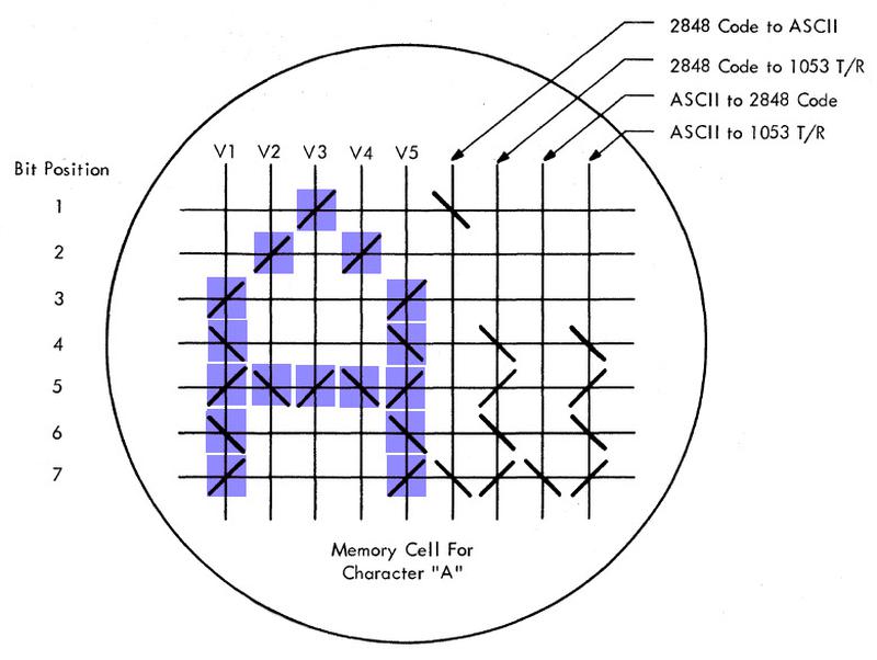
Another curious feature of the IBM 2260 display is how it converted the 6-bit character code into the 5×7 block of pixels representing the character. It used a special core memory plane that only had cores for 1 bits and omitted cores for 0 bits, so it acted as a read-only memory. The result is you could actually see the characters in core plane, as illustrated below. The core plane holds nine 7-bit words for each of the 64 characters: the first five words held the pixel block, while the four other words were a lookup table to convert the EBCDIC character code (2848 code) to or from ASCII or a tilt-shift code used to control the Selectric-like printer (Model 1053).
Part of the character generation core plane, showing the segment for the character 'A'. The diagonal lines indicate ferrite cores; I've colored the cores storing the character image. The core plane was a 72×56 grid in total representing 64 characters. Image based on 2260 Field Engineering Theory of Operation Manual p2-82. -
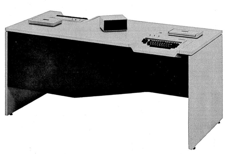
IBM apparently liked the idea of splitting display hardware between two users, because they did that with the IBM 3742 Dual Data Station (1973). This system let two operators enter data onto 8" floppy disks. The bizarre part is that it had a single vertically-mounted CRT display. The small black box in the middle of the desk is a pair of mirrors that showed half the screen to each operator. The result was a very squat display with just three lines of 40 characters, enough for a status line and 80 characters of data.
The IBM 3742 Dual Data Station allowed two operators to type data onto floppy disks. Image from IBM 3740 System Summary. -
The lines of text in the screenshot appear closer together than double-spaced, even though they are double-spaced. The reason is that the dots on the screen are a bit larger than one pixel, so they encroach into the space between the lines. In other words, the display alternates 7 lines of character pixels and 7 blank lines, but it looks more like 9 lines of character pixels and 5 blank lines. ↩
-
Televisions and CRT displays normally use a raster scan, scanning the electron beam across the screen in horizontal scan lines, making a series of lines from top-to-bottom. The 2260, on the other hand, has highly-unusual vertical scan lines; the scan lines are top-to-bottom, and the series of lines progressed left-to-right across the screen. I haven't been able to determine any reason why the 2260 has vertical scanlines. I assume it made the timing work out better somehow. ↩
-
Here are my calculations on the maximum number of lines that could be displayed by the 2260. A 250 nanosecond pixel rate and 30 Hertz refresh give a maximum of 133,333 pixels that can be displayed on the screen. If each character is 6×7 pixels and there are 80 characters per line, 39.7 lines could be on the screen. Vertical refresh takes 1/3 of the time because of interaction with the delay lines,17 dropping this to 26.5 lines. Because the 2260 splits pixels across two displays, that yields at most 13.25 lines on the display, ignoring horizontal refresh. Therefore, 12 lines of text are about what the hardware could support. (I should point out that it's possible they decided on 12 lines first and selected the other design characteristics to fit this.) Note that the next reasonable line size would be 16 lines. The low-end model displayed 6 lines of 40 characters (i.e. 3 punch cards), so the next step for it would be 8 lines of 40 characters (four punch cards). Since the high-end model uses four buffers, that would yield 16 lines. The point is that it would have been a large jump to go beyond 12 lines. ↩
-
The 2260 came in three models. Model 1 displayed 6 lines of 40 characters. Model 2 displayed 12 lines of 40 characters. Model 3 displayed 12 lines of 80 characters. The main difference in implementation was that they used 1, 2, and 4 buffers respectively. The 40-character models refreshed at 60 Hz rather than 30 Hz, since they had half the (vertical) scanlines. ↩
-
The aspect ratio of the IBM 2260's text was very different from the screen's aspect ratio. With the bezel, the screen's useful display area is 9.5 by 5.7 inches (5:3 ratio). Note that the aspect ratio of the text was very different from a standard 4:3 ratio. The 40×6 display format is 6.5 by 2.25 inches (almost 3:1 ratio). The 40×12 display format is 6.5 by 4.5 inches (a bit over 4:3 ratio). The 80×12 display format is 9 by 3 inches (3:1 ratio). Information on the 2260's screen size is in the FE Manual chapter 2. ↩
-
The 1974 Datapro report gives the price for the IBM 2260 system as $1270 to $2140 for the display unit and $15,715 to $86,365 for the controller. The IBM 3270 in comparison was $4,000 to $7,435 for the display unit (3277) and $6,500 to $15,725 for the controller. Note that compared to the 2260, the 3270 moved much of the complexity from the controller to the display unit, which is reflected in the prices. ↩
-
The IBM 3270 was a line of terminals. Like the 2260, it consisted of a 3271 or 3272 Control Unit (interesting video here) along with the terminals (3275 or 3277 Display Stations). These could display 40×12 or 80×24. For simplicity, I'll refer to the whole system as the 3270. Over the years, IBM introduced more models in the 3270 line, including color and graphics terminals, supporting lower case as well as display sizes such as 80×32, 80×43, and 132×27. The 3270 PC (1983) was an enhanced IBM PC that acted as a 3270 terminal. However, I'm going to focus on the original 3270 terminals, since those had the most influence. ↩
-
A 480-bit shift register might seem like a strange size, since it's not a power of two. However, since shift registers don't have address bits, they can be arbitrary sizes. For instance, Collins made dual 66-bit shift registers, to support 64-bit data plus 2 parity bits. Fairchild made 480-bit shift registers for CRT displays. 500-bit shift registers were built "to operate in equipment where storage lengths in 100 bit multiples are required." Texas Instruments built dynamic bipolar shift registers in 253-bit, 349-bit, and 501-bit sizes which were useful for Digital Differential Analyzers. The point is that shift registers can be built in arbitrary sizes, so there is no need to use a power of two.
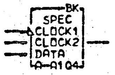
Schematic symbol for the 480-bit shift register in the 3270. Inputs are data and the two-phase clock. "SPEC" indicates a special circuit. From the ALD, page MP151.The 3270 used banks of ten 480-bit shift registers to store 480 10-bit data words (9 bits and parity), unlike the earlier 2260 delay lines, which stored pixels. ↩
-
Software support for the 3270 included DIDOCS (Device Independent Display Operator Console Support), using the 3270 as a mainframe system console; VIDEO/370 (Visual Data Entry Online), a program that allowed customers to design forms for data entry; DATA/360, a program that emulated an IBM 29 card punch, but provided editing and validation; IMS (Information Management System); (CICS) Customer Information Control System, which allowed interaction with a database; IQF (Interactive Query Facility), another database system; and TSO (Time Sharing Option). ↩
-
The 132-column width for terminals was motivated by the ubiquity of IBM's 132-column printers. ↩
-
The DataMaster's influence on the IBM PC is described in two articles by Dr. Dave Bradley: The creation of the IBM PC in Byte, Sept. 1990; and A personal history of the IBM PC, IEEE Computer, Aug 2011 (paywalled). The Wikipedia article DataMaster System/23 also provides information. ↩
-
Dr. Bradley explained that the designers of the IBM PC weren't concerned with compatibility with other systems. For instance, you might expect the IBM PC to be compatible with the 3270 terminal. However, the IBM PC's keyboard had 10 function keys while the IBM 3270 terminal had 12. This incompatibility was finally fixed with the IBM PS/2 keyboard (1987). ↩
-
To confirm the popularity of 80×24 terminals versus 80×25 terminals, I took a look at the GNU termcap file. I counted and found there were over 5 times as many 24-line terminals as 25-line terminals, and the 25-line terminals were mostly PC-based. 80-column terminals were over 5 times as popular as 132-column terminals, the runner-up. ↩
Well, some remarks:
ReplyDeletea) IBM calls what otherwise is known as terminal a Display - that's because they originally were mere displays without any local handling or even storage.
b) 3270 names the terminal subsystem as whole, that is controllers, displays and printers.
c) Displays within the 3270 system were 3277 (two versions: M1 with 40x12 and M2 with 80x24), the 3278 you mention, and the 3279, offering a colour display (8 colours)
d) Since you mention the 3278 as a terminal, then you should do so with the 3277.
e) There is no 80x24 model. All of them had a status line. Including the 3277.
f) The designers didn't 'squeeze in' a few more lines, but it was a requirement to handle a 3270 screen - which meant 25 liens, as there is no 24 line model.
(in fact, the scan shows clearly that they were originally intended to go with 192 lines like many other microcomputers of that time - und til required to enable it to show a full 3277/78/79 screed with 24+1 lines.
Oh, and one more, the 3279 is also the reason why the CGA features 8 colours in two intensities, as that's exactly what the 3279 does and an emulation would need.
ReplyDeleteThe PC can't deny being created in Boca Raton :)
The 2260, that sounds so wonderful. The terminal is a truly "thin" device with no intelligence, and heavy footsteps in some not too remote location can mess up the displays on all of the terminals attached to the controller. What's not to love?
ReplyDeleteUnknown: The 3277 didn't have a status line, but three status lights next to the display. It had 24 lines in total. The status line (Operator Information Area) was introduced in the 3278. This can be verified in the manuals, which are online at bitsavers.
ReplyDeleteAlso, 3270 emulation was not a requirement or goal for the IBM PC, and didn't lead to the 25th line. I would much prefer to have a tidy story where the 3270 led to the PC's display, but unfortunately that's not the case. I talked to two of the original IBM PC engineers to check on this. The said the IBM PC team felt absolutely no need to be compatible with other IBM products. In particular, several features of the PC made 3270 compatibility harder: the use of ASCII instead of EBCDIC, little-endian words, and 10 function keys instead of 12.
One of the details you didn't mention (because that wasn't the point of the article, I suppose) was the terminal addressing. 3270s had two types of controllers: those that could attach to a byte multiplexor channel on a mainframe and those typically at remote locations attached to a modem. The 3270 addressing scheme allowed for 32 controllers on a channel with each controller able to support 32 terminals. I never saw this even remotely attempted, especially at a remote location due to bandwidth constraints. I think the biggest cluster I saw was 3 controllers, each with 15-20 terminals. Since the 3270 communications protocol was polled, if everyone hit enter at once it could take a long time for the last terminal to send its data.
ReplyDeleteGetting back to the point of the article, one of my jobs in the '70s was to allow 3270s to attach to UNIX. This was a nightmare in many respects. The polled protocol, the full screen read and writes, the difference between EBCDIC and ASCII, the lack of all sorts of normal ASCII keys. The first time we got a "termcap" for it written, watching it try to do vi or emacs (or rogue!) was enough to send the programmers into fits of laughter.
While the IBM 2260 Display Station had its electronics in an external cabinet, as you show, even with 1965 technology, there was also the 2265 Display Station, which was self-contained, and only a little bigger than a 2260.
ReplyDeletequadibloc: The 2265 wasn't quite self-contained, it still required the 2845 Display Control. Admittedly, the 2845 was a much smaller cabinet: 2' x 2' and 110 pounds.
ReplyDeleteThe VT100 was the successor to the VT52, from which it retained many characteristics. According to section
ReplyDelete4.3.1.1 of the VT52 Maintenance Manual
4.3.1.1 RAM and Memory Buffer -- The RAM consists of fourteen 2102 chips arranged to provide two, 1024 × 7-bit read/write memories (Figure 4-6). To the programmer, the memory appears as a 2048 × 7-bit memory because the RAM addressing scheme assigns all even addresses to one 1024 memory (page 1) and all odd addresses to the other memory (page 2); 1920 locations are used to store a screenful of characters (24 lines × 80 columns); the remaining 128 locations are used by the microprogram as a scratchpad memory, i.e., temporary storage of keyboard characters, cursor address, etc.
So it had a 24x80 (by 7 bit) screen; maybe 48 7-bit values wouldn't have been enough scratchpad for the microprogram? The layout of scratchpad memory has 90 cells,( some of which are blank).
Anyway, by VT100 times they used an 8080 instead of a specialized video processor.
You could use the VT100 in 14x132 mode. 15x132 would take 40 more characters than the default 24x80, and apparently wasn't possible with the available RAM (3k allocating 2.3k for screen display and the remainder scratch section 4.15.3) You could upgrade with the 'Advanced Video Option' which adds a fourth 1Kx8 chip to get 24x132.
So, is the 132x27 terminal size of the 3270 terminal system mere coincidence, or was someone in IBM's naming department feeling a bit clever (assuming 3270s supportes 132x27 from the start)?
ReplyDeleteAh. This explains an oddity from my past - early 1980s I bought a terminal from a junk shop. It had a standard composite video input to the display, and a keyboard that had almost no electronics; the matrix fed out to a large multipole connector. As my experience was with vt100s, I couldn't understand that, so I ignored it and used the display with my BBC micro.
ReplyDeleteThere's a very small chance it still exists, possibly in the loft at my parents..
Funny story: While we were demonstrating a breadboard of the VT00 to Gordon Bell, CTO, he asked me if we could make the screen display a 132 character line to match the output of line printers.
ReplyDeleteI said I would look into it, but thought to myself that with the resolution we had on-screen it would be unreadable. Thank goodness, I did not say that to Gordon.
I did some character bit sketches that reinforced my feeling, but to be sure I went to the lab to see if I could simulate it. Since I had designed the tv display, I knew how to shrink the horizontal deflection to allow 80 characters to display in the space they would be on a 132 character line. And I found they were completely legible! Spec changed. Our brains do a good job of recognizing fuzzy characters.
In hindsight, this turned into a big profit for Digital. Since we were under cost pressure we did not put in enough memory to display a 24 x 132 screen in the base VT100, but we sold an add on a memory card at somewhat high-price. Most people bought the add-on.
And then in the mid-1980s, Facit released the Facit Twist, a mostly-VT102-compatible terminal that used a rotatable screen and a switch actuated by an excentricity in the swivel to either be an 80x24 or 80x72 terminal.
ReplyDeleteSeeing that picture of the acoustic delay line unit opened up almost made me cry.
ReplyDeleteWhy you may ask? My dad was an IBM CE and used to bring home bits of dead System 360 for us kids to gawk at, this delay line being one of them. My brother and I opened up the unit and of course it wasn't long before we had the beautiful shiny gap-spaced coil of nichrome(?) wire unravelled and stretched into a twanging wire, then (I can't remember) probably chucked in the bin...
As for the System/23, I had a dead motherboard from one, beautifully made with about a 5-layer PCB I think. I may be mistaking it for another IBM board but I have a notion the dynamic ram chips on it might have been double-decker stacked, and I wondered how they differentiated addressing the chips that way. Thinking about it now I suppose they could have had an inverter added to one of the pair, but that would mean having a slightly different die for each one.
The dies are the same, but the pinout is slightly different. RAS and CAS signals are conducted by different pins and there are also two NC pins for each IC so the piggybacked signal can flow without interference.
DeleteBy the way, do you still have that System/23 dead motherboard?
Incredible historical information as ever, Ken.
ReplyDeleteTo go off on a slight tangent, as it's a shower-thought rabbit hole search that brought me to this page ... did any of the IBM PC guys say anything regarding the whys of differences between the Datamaster display and the MDA? They share a scanrate, but the character cell is 9 pixels instead of 10, and the dotclock is lower... but 88.2% not 90%.
Trying to figure why they went with the odd 16.257MHz clock for that and EGA (then another that was 4/3rds of it for the PC3270) is something of a puzzle I've had for a while, and finding out about the Datamaster on this occasion was what I thought would be the answer ... until I ran the numbers and found it was wrong. Agh.
(Looks like DM uses 18.432MHz and 100 chars per line, vs MDA with 98, thus 1000 and 882 pixels... And I suppose the DM must have had a status line with its otherwise regular terminal-like 80x24 display, unless they literally did "squeeze in an extra line" with MDA to support that, trimming down the blanking in both dimensions? DM however being little endian because of using an 8085, and maybe using ASCII encoding too rather than EBCDIC as it was meant more as a standalone system transferring data on disk...)