My Sonicare electric toothbrush recently quit working, so I took it apart and examined the interesting circuitry inside. There's much more complexity than I expected inside a toothbrush, especially in the mechanism that drives the brush head at 31,000 strokes per minute. Internally, the brush appears to be designed for quality rather than ease of manufacturing. Unfortunately, moisture can get in, causing reliability problems.
The toothbrush is a Sonicare Flexcare Platinum with more features than you'd expect in a toothbrush: three brushing modes, three intensities and a couple timers, along with 10 LEDs to indicate its status. A pressure sensor in the toothbrush changes the vibration if you apply too much pressure while brushing. The toothbrush uses wireless inductive charging so it charges when set on the base. (This toothbrush may seem overly complicated, but it's nothing compared to the new model that includes Bluetooth.)[1]
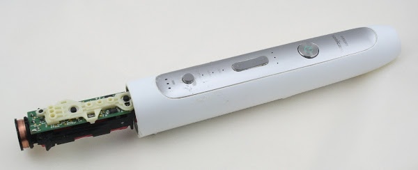
The first step was to remove the toothbrush base, allowing the toothbrush mechanism to be removed from the case. The toothbrush head mounts on the right; it needed to be removed to disassemble the toothbrush. At the left is the charging coil used to wirelessly charge the toothbrush.
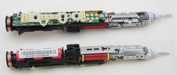
The photos below show the top and bottom of the toothbrush internals. I expected to find a simple, low-cost mechanism, so I was surprised at how much complexity there was inside. The vibration mechanism (right) is built from multiple metal and plastic parts screwed together, requiring more expensive assembly than I expected. The circuit board is literally gold-plated and has a lot of components, even if it doesn't quite reach Apple's level of complexity. Overall, the toothbrush's internal design is high quality (except, of course, for the fact that it quit working, as did an earlier one).
The brush contains several key components, as can be seen above. In the center is the large red coil that causes the toothbrush to vibrate. On the right is the vibration mechanism, which has a powerful magnet that is moved by the coil. The brush head snaps on at the right. The battery (red, left) takes up about a third of the toothbrush. The long, thin circuit board (green) has the circuitry to operate the toothbrush. A white spacer sits on top of the circuit board, with holes for the LEDs and buttons.
The photo below shows the brush mechanism partially disassembled and separated from the electronics. The toothbrush still powers on in this state, as you can see from the illuminated LEDs. Note the flexible brown ribbon cable between the center of the brush mechanism and the electronics board. This connects the pressure sensor on the brush mechanism to the electronics board.
The diagram below shows the main components on the circuit board. The buttons are the most visible feature. The gold circles at the left are used to program the microcontroller. The MOSFET transistor switch the coil on and off to produce vibrations. Ten LEDs are scattered across the board. At the right, the diode bridge is part of the charging circuit.
The circuit board is covered with tiny gold circles. These are test points, allowing test connections to most parts of the board. For instance, each LED and each button has a test point that can be used to test the component. During testing, spring loaded pogo pins on the test circuit make contact with these test points on the toothbrush board. The number of test points (about 56) looks like overkill to me.
The diagram below shows the components on the back of the circuit board. The toothbrush is controlled by a mid-range 8-bit microcontroller, the PIC16F1516.[2] This chip contains the code for all the toothbrush functions: reading the buttons, lighting the LEDs, controlling the coil, and managing charging. There are too many LEDs (10) for the chip to control individually, so eight of the LEDs are controlled by a separate LED driver chip.[3]
The microcontroller is an off-the-shelf part, not a custom chip, so it needs to be programmed with the right software. This is done during manufacturing through the large gold circles and triangle near the end of the toothbrush.[4] The resonator provides the clock signal for the microcontroller's timing.[5]
The driver mechanism and the H bridge circuit
The toothbrush head is driven by an electromagnetic coil that moves a magnet. The coil has two halves, wired in opposite directions, so the sides will have opposite magnetic fields. The coil is pulsed one way to rotate the magnet one direction, and then pulsed the opposite way to rotate the magnet the other direction. The result is the high-speed brushing vibration.The diagram below shows the driver mechanism disassembled. The coil constantly switches polarity so the north pole will switch from the top to bottom (the yellow and blue poles of the coil). The magnet has poles on the front and back edges (perpendicular to the coils), so it will attempt to rotate back and forth to line up with the coil, along the long axis of the toothbrush. The mechanism limits the rotation to a few degrees, resulting in a rotational vibration back and forth rather than spinning like a motor. This rotational vibration is transmitted to the toothbrush head by the torsion bar causing the head and bristles to vibrate. More details on the driver mechanism are here.
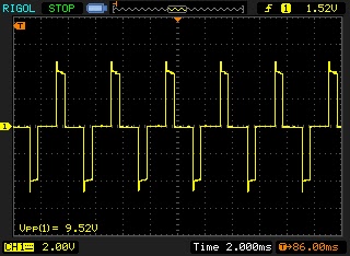
The figure below shows the voltage across the coil. Every 2 milliseconds, there is a 4 volt pulse across the coil, followed by a negative 4 volt pulse. The pulses generate the reversing magnetic field that drives the magnet and causes the toothbrush to vibrate. If you count the positive and negative pulses as separate brush strokes, you get the advertised 31,000 brush strokes per minute. (Although counting an up-down cycle as a single stroke rather than two would make more sense to me.)
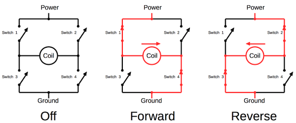
You might think that driving a coil in two directions would use two switches, but instead it uses four, in a common circuit called an H bridge, as shown below. If switches 1 and 4 are closed, current flows in the forward direction. If switches 2 and 3 are closed, current flows in the reverse direction. In the toothbrush, transistors are used for the switches, and are turned on and off by the microcontroller.[6] An H bridge is often used to control motors that need to go forwards and reverse, for example in a hoverboard.
Pressure sensor
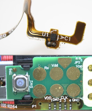
One of the features of this toothbrush is a pressure sensor. If you press too hard while brushing, the vibrations start pulsing and the LEDs flash. The sensor itself is a tiny mystery chip (below) mounted on the drive assembly, and connected to the electronics board with a thin flexible cable. The cable is labeled with Vdd (1), Data (2), Clock (3), and Ground (4), so the sensor is probably sending a stream of bits using an I2C protocol. My suspicion is the sensor is a Hall effect magnetic field sensor that detects a change in the magnetic field if pressure is preventing the magnet from vibrating. The chip doesn't seem to be in a position to measure actual pressure, which is why I suspect it's measuring the magnetic field instead.
Charging
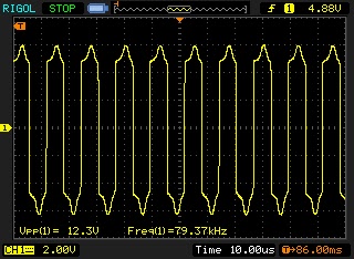
To charge the toothbrush, it is set on a stand and charges inductively without physically being plugged in. A coil in the stand is magnetically coupled to a coil in the toothbrush, transmitting the power wirelessly. You can see the coil at the bottom of the toothbrush. When set on the stand, the coil picks up about 12 volts, which is used to charge the battery. The power is transmitted at high frequency (80kHz) for efficiency.The coil is connected to a diode bridge that converts the power to DC. It then goes through a transistor circuit that regulates the charging, as directed by the microcontroller. The battery in the toothbrush is a Sanyo Li-ion rechargeable battery, which is said to be 3.7V but I measured 4.0V.[7]
The toothbrush is designed to conserve battery by using very little power when not in use. The microcontroller has a low power standby mode when it is waiting for a button press. When the toothbrush is activated, a transistor energizes the LEDs and the LED driver chip, while another circuit powers up the pressure sensor. This prevents these components from draining the battery while the toothbrush is not in use.
Conclusion
Overall, I was surprised by how much electronics was inside the toothbrush, as well as the complexity of the drive mechanism. It was designed with quality in mind, not low-cost production. Unfortunately, the brush has reliability issues—this was the second one to fail on me. The problem appears to be water seeping in around the shaft, eventually damaging the internals.Some other Sonicare teardowns are here, here and here. I would have expected different models to be based on similar electronics that just changed the LEDs, buttons and software. Surprisingly the different teardowns show a variety of microcontrollers, circuitry, and drive coils. Some models even move the magnets from the toothbrush unit to the brush head.
Unfortunately after disassembling my toothbrush I was unable to fix its problem. But at least I got an interesting teardown out of it!
To find out about my latest teardowns, follow kenshirriff on Twitter.
Notes and references
[1] It's ironic for a toothbrush to include Bluetooth technology because Bluetooth is named after Harald Bluetooth, a tenth century Danish king who was called Bluetooth because he had a bad, discolored tooth. The Bluetooth logo itself is formed by combining two runes from the king's name.[2] The PIC microcontroller runs at 16 megahertz. It has 8K of flash memory for the program, as well as 512 bytes of RAM (the RAM on microcontrollers is usually very small) and 128 bytes of flash memory for data. It includes analog-to-digital conversion, which I think is used to monitor the charging voltage. The toothbrush's 8-bit microcontroller is less powerful than the 16-bit microcontroller inside a Macbook power supply.
[3] The LEDs are controlled by a 75HC595A serial to 8-bit output chip. The benefit of this chip is that the microcontroller would use 8 pins to control 8 LEDs, while the microcontroller only uses 3 pins to communicate with the serial chip, freeing up 5 pins for other tasks.
[4] Programming of the chip is done using the ISCP protocol. This uses the programming contacts labeled Vdd, Vpp, Tx, and Ground, as well as the triangle contact, which provides the ISCP data. For some reason, the Tx and Rx circles are also connected to the chips's UART serial pins, allowing serial communication with the microcontroller. I'm not sure why one would want to communicate with the chip outside programming. Maybe there's serial communication with the microcontroller as part of testing. Or maybe the NSA can download information on your brushing habits :-)
[5] The resonator is a 3-pin unit with built-in load capacitors, similar to a quartz crystal oscillator. I suspect it's a CERALOCK®, or something similar.
[6] The H bridge uses a 6866S 20V dual N-channel MOSFET on the low side and a 6963SD 20V dual P-channel MOSFET on the high side.
[7] The charger circuit is puzzlingly simple. The voltage from the diode bridge goes through a microcontroller-controlled transistor (Q5) and then to the battery (through a tiny fuse), without the filtering, voltage regulator or battery voltage monitoring I'd expect. The microcontroller is connected to the AC side of the diode bridge, and presumably is monitoring the input voltage waveform.


Thanks for the very illustrative teardown! I was surprised also by the number of testpoints - this is more like what I see in high-rel and automotive products, for example, where pogo-pin in-circuit test is still in common use. Perhaps because of the relatively harsh environment of this product (moist, drops and shocks) the manufacturer keeps with this test strategy?
ReplyDeletePerhaps the "pressure sensor" feature is accomplished by monitoring the motor current during brushing? If you press too hard, you load the motor, and the current increases. This would be much easier (and cheaper) to measure than magnetic field intensity.
Again, thank you!
-tom
Impressive. Assuming the sensor doesn't need the back channel for configuration or similar, could it be some simpler SPI-like protocol, rather than I2C?
ReplyDeleteI believe you'll find that their definition of stroke is the proper one, meaning a movement in a single direction.
ReplyDelete4-stroke engines perform their 4 strokes in 2 cycles, and 2-stroke engines perform their 2 strokes in only one cycle of the piston.
If you're looking for a word that means both the forward and return stroke... you're thinking of "cycle", of course.
Very nice article. The pressure sensor is AS5510 by austriamicrosystems. Hall sensor with I2C Interface.
ReplyDeleteI have the Bluetooth version of this brush and I'm wondering whether it's possible to open it to maintain it then get it back together again. I didn't see HOW you got the bottom off...was it destructive? I'm pretty skilled at teardown and reassembly of this kind of thing but the ovoid shape has me a bit afraid to try without damaging it, though the slot in the charging "port" suggests maybe a screwdriver and an 1/8 or a turn or something?
ReplyDeleteRob: supposedly the bottom of the toothbrush just pries/pushes out (link) but it was a bit destructive when I did it, so be careful.
ReplyDeleteTo open it you can put it into a vise (with appropriate scratch protection), the slightly more pointed sides of the ovoid shape making contact with the vise. Then slowly (!) apply pressure and the whole thing will suddenly pop open without any damage at all. Thanks for the teardown, just used the battery and charger of a broken toothbrush to retrofit my old shaver with LiPo power and wireless charging :)
ReplyDeleteThanks for this great article! A question. Mine stopped working after getting a charger of 240v. I guess I could try recoiling it with the proper wire (though it shows continuity, it would still show if some of the wire enamel was burnt) but I will like to try a 9v *AC* adapter. Would that work? Actually would I need a 6v AC adapter out a 12v AC adapter? (I don't really know how these things are specified, i.e is a 9v ac adapter -4.5 to +4.5v? Or -9 to 9v -or that actually make it a 18v ac adapter) Anyway, would a 9v ac adapter work (given that you seem to understand very well the circuitry)? I guess it's better to underpower than overpower? Or you see an obvious problem there? (All this because I don't have a 12v AC adapter.) Ok too long but hopefully I can revive my brush. (I revived my wife's by disassembling the pressure switch and cleaning it! -yeah, I felt like I knew what I was doing! :) ) Thanks!
ReplyDeleteAnonymous: a 9V AC adaptor is -12.8 volts to +12.8 volts. This may seem strange but AC is measured using RMS voltages. It sounds like you're planning to feed the AC directly into the toothbrush, which sounds sketchy. Note that the inductive charging signal is 80 kHz, which is very different from the 60 Hz from an AC adapter.
ReplyDeleteThanks for the reply and reminder of RMS! I forgot the 80khz. How does a coil achieve that at the output if the input is 60hz? In other words how could I increase the frequency? (BTW, yes, I want to bypass the secondary coil, well the whole "transformer" actually.) Did you measure the output of the coil while disconnected from any loads? (I'm just wondering in case it was not changed by some capacitor or something.) Thanks!
DeleteAnonymous: the base has a switching power supply to convert the 60 Hz line voltage to the 80 kHz inductor signal. I measured the voltage across the coil inside the toothbrush.
ReplyDeleteOh, then my approach is not going to work. Which base model is it? I think mine only has a coil (the equivalent to a primary coil in a transformer) and the brush has the secondary coil. Thanks!
DeleteHelp !!
ReplyDeleteSURFACE MOUNT FUSE issue:
My diamondcare HA-9350 recently failed.
The rubber gasket at the top melted and BADLY deformed the rubber seal for some reason and water got in.
Gasket has burn marks in the deformed rubber.
I guess half of the H-bridge got shorted and the coil stayed energized too long creating alot of heat until the battery died.
Water got onto the micro controller pins and "corrosion-shorted" the reset (pin-1) out and also drained the battery.
I cleaned it with alcohol and a toothbrush and toothpick and it came back to life after I slipped the metallic bottom back on and put it back into the charger.
(the charge LED's worked start to finish)
But, when I tested it in my hand by pressing the on button I must have touched the wrong spot and it stopped working again. Zero signs of life.
I looked around and there is a very-very tiny royal-blue SMT fuse "F1", with capitol "P" marked on it. It is mid-board by yellow-"CR4"
If I jumper it, it works again.
Fuse size could be 0402 size, or next size up.
It is as long as the pins on the SMT 16F627, and about two of it's pins wide (not including pin gap).
I need to find the value of that fuse so I can replace it with the right one.
I can replace parts that size, so please don't get hung up on that.
any suggestions on how to find out its value OTHER than an in-circuit current meter??
plz reply:
doug seven zero 0 seven (<---use numbers not spelled) (At) H0tmale daught calm
2-April'2018
Hi,
ReplyDeleteyou can find the fuse value at the Farnell Webside, the capitol "P" represent 3A
for the fuse.
If no LED-Flashing is working the LED-Driver is gone.
Best regards
Hi,
ReplyDeleteIm working on a 18650 battery powered project that would be awesome use use the sonicare inductive charger to charge it -- do you have a diagram of the induction charging circuit the sonicare uses? I was also thinking of sacrificing one and using the test points to connect ... but wouldnt be ideal for my purpose.
Thank you very much!
Hello Ken,
ReplyDeleteThank you for this informative article. I am wondering if you opened up the charger stand as well. I'd like to know how that works. It should step down the AC mains voltage, rectify it (AC --> DC) and then feed it through the transmitter coil while changing its polarity (DC --> AC) at same time. It should be done at high frequencies as you said. I have opened up one and tried to back engineer the circuit to no avail.
Cheers
I also somehow blew the fuse, so jumped it instead of replacing. If this destroys the internal electronics I’m okay with that, but concerned about thermal runaway on the battery. Will this occur?
ReplyDeleteThanks!
In the future, you should list all of the important ICs that were used! I'm currently doing research to build an inductive charging circuit and would love to know what chips are used in typical commercial applications
ReplyDeleteA crazy idea, but do you think it is possible to convert this brush into the torch keeping all the electronics, removing the coil part and installing the LED instead?
ReplyDeleteThis seems like the place to mention this since it may help someone else who lands here. I had a problem with my Philips Platinum but it wasn't electronic. The toothbrush head at some point started flopping about wobbling loosely from side to side, and while it still worked it was making a raucous buzzing sound rather than the usual smooth hum.
ReplyDeleteThe fix was fortunately easy, though not obvious. Extracting the guts wasn't too hard using the advice above. Up near the top of the mechanism there is a very small Phillips screw. This is supposed to lock the metal stem (onto which you push the brush head) to the vibrating electromagnet assembly.
It turns out this screw had gotten loose after 3 1/2 years. So just back off (but do not remove) the screw a bit and then press the end of the stem down hard towards the body of the toothbrush. This requires a moderate amount of force. Also note that the stem is not exactly in line with the main body but rather canted a few degrees to the front.
Then tighten the screw. It should now grab the end of the vibrator assembly and restore the toothbrush to its original state. QED.
How many loops are in the coil?
ReplyDeleteHello, tried to use a generic inductive phone charger (input 5V - 2A, output 5V - 1A) with 3 USB power supplies (all input 110 -240V 0.2A, output 5.0V, 5.2V & 5.3V, Output 1.0A, 1.2A & 1.3a) to see if my wife's (already fuly charged) Sonicare would charge. Well the toothbrush leds start blinking sequentially like it is charging but very fast. On the oem charger the leds just remain on except for a short time after the brush has been on the phone charger when the leds blink slowly as in normal charging & then stop. I am assuming the phone charger is actually discharging away the charge remaining in the brush. The opposite of what I want, ha! Ha! :)
ReplyDeleteHI, anybody know what transistor marked as Q4?
ReplyDeleteIt have mark NB1Q or N81Q
The shaft area got loose on our HX6920 and I replaced the shaft. It did not fix the problem. The shaft runs in a plastic bearing and if too much side load is used, the plastic wears out. On eBay I purchase the top half assembly for a little over $13 which includes the plastic piece. The issue I had was removing the top half from the electronics. I ended up removing the spring and rubber piece between the motor and the battery. This allowed the top to slide up and down but it would not come off. I found two small plastic clips that are hidden under the motor. You need a very small screw drive to release those clips so the top section will slide off the electronics section. This seemed like a cheap fix for a nice tooth brush.
ReplyDeleteMy HX6220 Sonicare circuit board E131175 looks perfectly clean and healthy, the charging LED operates in the usual manner except that it charges indefinitely, never sensing full charge even though, the battery is fully charged. The tiny fuse is intact. But no motor function occurs when the switch is pressed.
ReplyDeleteMaybe a µC reset is needed, because: After years of reliable service the original battery succumbed, but in haste I replaced the two NiMH cells with a single charged Li-ion cell (that's what I had at the time). All was initially normal but operating time diminished over a few days to zero. So I removed the Li-ion cell then installed two new charged NiMH cells in the original manner. The installations and all work was pristine with no damage. But now no motor function occurs, alas. (The fuse is still intact.)
Maybe the Li-ion period resulted in a charging data history in the µC which causes it to view the new NiMH battery as fully depleted. Maybe that's also why it never finishes a charging cycle. So I'd like to fully reset the history data without erasing the program data if possible. Any ideas? Or any other insights appreciated. A schematic would be wonderful too of course. Many thanks all!
(My email address is at AirplaneHome (see oh em TLD). Also the two motor driver FETs seem fine to me - there's no visual evidence of thermal or other stress. And more importantly they seem to receive no oscillating signal when the button is pressed, so my sense is that the µC isn't generating a motor drive signal. Per my speculation because it thinks the battery is dead relative to Li-ion voltage history data.)