The Alto was a revolutionary computer, designed at Xerox PARC in 1973 to investigate personal computing. It introduced the GUI, Ethernet and laser printers to the world, among other things. Y Combinator received an Alto from computer visionary Alan Kay and I'm helping restore the system, along with Marc Verdiell, Luca Severini, Ron Crane, Carl Claunch and Ed Thelen (from the IBM 1401 restoration team). Marc's video of this restoration session is below.
The missing disk sector task
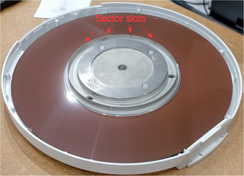
In the Alto, like most modern computers, each machine instruction is implemented in an even more primitive form of code called microcode. But unlike most computers, the Alto also implements some of its low-level software in microcode. Part of the Alto's design philosophy was to use software (i.e. microcode) instead of hardware where possible. For instance, a microcode sector task processes each disk sector and a word task stores each word of data as it arrives from the disk drive; most computers do this with DMA hardware.Last week we hooked a logic analyzer to the Alto to trace the executing microcode and found the disk sector task was failing to run. Each track on the Alto's hard disk is divided into 12 sectors, with 12 slots in the hub to indicate the sectors. We verified that the disk drive was detecting these slots and sending the sector pulses every 3.33 milliseconds. The disk sector task is supposed to run for each sector and perform any disk command, but the logic analyzer showed that this task was not running.
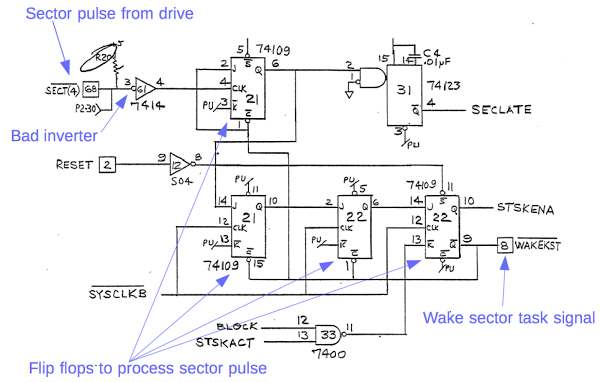
Why was the sector task not running? The disk interface board provides a signal to indicate when the sector task should run (WAKEST), but we found it was not being activated even though the disk drive was providing sector pulses to the disk interface board. Looking at the disk interface board schematic, the sector pulse circuit is fairly simple: just a few flip flops. (You don't need to understand the schematic below. The key point is the sector pulse comes in on the left, goes through a few chips, and the wakeup signal comes out on the right.) I've heard that old TTL flip flops fail regularly, so I figured one of the flip flop chips had failed. We decided to hook up an oscilloscope and see where things were going wrong, but one problem stood in our way.
The extender card
The Alto consists of 13 circuit cards plugged into a wire-wrapped backplane, making them inaccessible to probing. Fortunately, the Living Computer Museum gave us an extender card, a board that goes between an Alto board and the backplane, physically extending the Alto board out of the cabinet where it can be diagnosed. Last week, we used the extender card to probe signals on the CPU control board. But no matter how hard I tried, I couldn't get the extender board to plug into the disk interface board's slot. Marc noticed out that the board was hitting something, and we realized that the disk interface board had a notch on the right, allowing the board to clear a bar that was in the way. The extender board, like most of the Alto boards, lacked this notch. A bit more investigation revealed that memory boards had a notch, but on the left.Why did some boards have notches? Most of the boards are powered with 5 volts. The memory boards also require -5 volts and +12 volts for the 4116 DRAM chips. The I/O boards (Ethernet and disk) have +/- 15 volts as well as 5 volts. The Alto backplane was apparently designed so you couldn't plug a board into a slot with the wrong voltages (which would have been catastrophic). Boards with unusual power requirements had a notch that allowed them to fit into slots wired with unusual voltages. The consequence was that we couldn't use the extender board with the disk interface without cutting a notch in it, which we did (see photo below).
We were worried that by cutting a notch in the extender board and using it in a slot where it wasn't intended we might destroy the computer in a spectacular show of sparks and smoke. The concern was that the extender board doesn't simply pass the 162 lines through, but wires all the ground lines to a ground plane and wires the +5 lines together. If the disk interface card had +15 volts where the extender board expected, say, +5 volts, the extender card would run +15 volts to all the chips and destroy them. We verified the wiring five times to make sure nothing would get shorted, plugged in the extender board, and turned the Alto on with some trepidation. Fortunately our calculations were correct and nothing blew up.
Debugging the disk interface
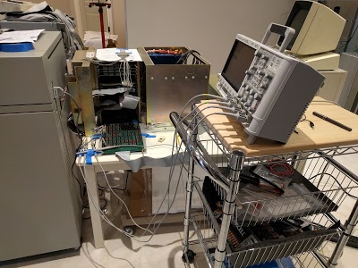
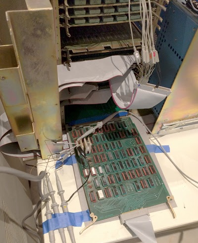
The photo below shows the disk interface card extended out of the Alto cabinet, with some oscilloscope probes attached to the flip flop chips. (The ribbon cable attached to the board connects to the disk drive, while the ribbon cable hanging above the board allows us to probe microcode signals with the logic analyzer.) Strangely, we didn't see any signals either going into the flip flops or coming out. We checked that the sector pulses were showing up in the logic analyzer, and on the connector from the disk drive, but the flip flops were getting nothing. Eventually we turned our attention to the inverter chip (see earlier schematic). We saw the sector signal going into the inverter, but not coming out. Could this simple chip be causing the problems?
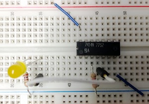
The 7414 TTL chip contains 6 inverters, which turn a 1 input into a 0 output and vice versa. We pulled the chip out of the disk interface board and tested it with a simple LED circuit (see photo below). Five of the six inverters worked fine, but one of the inverters had entirely failed. The chip is a bit unusual since it uses a Schmitt trigger—a circuit that cleans up noisy signals (such as the sector pulses that traveled over a long cable from the disk drive)—so we couldn't get a replacement at Fry's or Radio Shack. Were we stuck for the day?
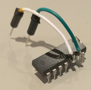
Fortunately we could work around the faulty chip. Carl studied the schematics and discovered that one of the good inverters on the chip was unused. We rewired the chip to replace the bad inverter with the unused good inverter by using an ugly but effective "dead bug" hack. We bent out the pins from the good inverter and attached wires. We cut off the pins from the bad inverter. Finally, we stuck the wires into the socket along with the IC, so the good inverter was wired in place of the bad inverter.
We booted the Alto and found that our chip hack actually worked and the system worked much better than before: the sector pulses got through the inverter, were processed by the flip flops, and triggered the sector task as we hoped. The sector task read the disk command from memory and sent it to the disk drive. The disk drive read the desired sector and started sending bits back. For each word, the disk word task read the word from the disk interface and stored it in memory. In summary, we were now reading data from disk!
Reading data from disk was a big milestone, since most of the system needed to be working properly for this to happen. Unfortunately the Alto didn't boot up, and we'll need to figure out where things went wrong. Is the boot block not running correctly? Is the read data corrupted? Is the disk returning an error at some point? Is our disk not a boot disk? Strangely, there was no sign of the parity errors we kept seeing last week.
The timeline diagram below shows task switching in the Alto over an interval of 700 microseconds.. You can see that the microcode is constantly switching between tasks. Today's accomplishment can be seen in the periodic execution of disk word task (KWT) at the bottom of the image; this task runs about every 9 microseconds when each word comes from the disk drive. The disk sector task (KSEC) runs at the start of the next sector (at which time the word task stops). Other tasks are the memory refresh task (MRT) and cursor task (CURT) that run periodically. (You can see where the higher-priority MRT task interrupted the KSEC task.) The lowest priority task is the Nova emulator (NOVEM), which runs program code when nothing else is happening. The numbers at the bottom show the micro-instruction count since boot; at this point we are 14.8 milliseconds into the boot process. I generated the diagram below by processing the logic analyzer output to show each running task. An interactive version is here, allowing zoom and pan with the mouse.

9 comments:
Could the last week parity error be caused by the use of the extender board ? Already "by construction" very tight memory signals timing that are messed up when the extender board is used ?
Emannuel: I don't think the parity errors are related to extender board (although anything's possible). We started our session with the extender board setup the same as last week but didn't see errors this week. Also, the extender board wasn't in the memory subsystem path; it would have affected microcode signals, not the memory signals. But it is a puzzle why the errors disappeared; I'm hoping they don't come back.
Have you painted a big warning on the extender board "WARNING NOTCH MAY KILL THE ALTO"
Or are you sure it's safe in al the possible slots :)
Great read and nice hack on the chip. Assume you ordered a new one to replace the hacked one.
> In summary, we were now reading data from disk!
Wow, there must've been quite the celebration there. Those were quite a few difficult hacks to get there.
Are you planning on getting a proper inverter chip to replace the faulty/hacked one? How about making a proper set of extender boards?
Since you didn't mention it, I assume the memory parity issue remains from last week?
Disk sector pulses every 3.33 microseconds seems too fast. Should that be milliseconds?
Interesting video, as always. I just checked my "collection" and I actually have two 74LS14N here. But I guess by the time I could ship them to you, you already found another source :)
Michael: thanks for the offer, but we found a 7414 locally. gp2000: oops, milliseconds. john: the parity errors mysteriously disappeared. john and Franc: the extender board we have should be okay in any of the slots.
http://www.jameco.com/webapp/wcs/stores/servlet/StoreCatalogDrillDownView?langId=-1&storeId=10001&catalogId=10001&categoryName=cat_1044&subCategoryName=ICs%20%26%20Semiconductors%20%2F%20Logic,%20TTL%20%2F%2074%20Series&category=104415
You may replace the SN7414 with the 74HC(T)14, or another Schmitt-Trigger flavored chip.
Post a Comment