I should warn the reader in advance that this article is more terse than my usual articles and intended for the small group of people interested in very low-level details of the ARM1. For the average reader I'd recommend my article Reverse engineering the ARM1 instead.
The microinstructions
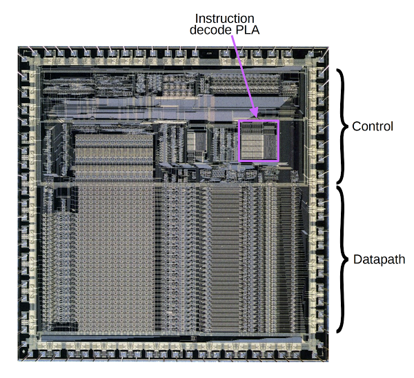
Each instruction in the ARM1 is broken down into 1 to 4 microinstructions. These microinstructions are stored in the instruction decode PLA (which acts as a ROM).[1] The ARM1's microcode is stored as 42 rows of 36-bit microinstructions. The 42 rows are split into 18 classes of instructions, each consisting of 1 to 4 microinstructions. (The microcode sequencer supports looping, allowing it to handle the bulk data transfer instructions LDM and STM which can take up to 17 cycles.)
To explain the microinstruction format, I'll use the LDR instruction as an example.
The LDR (Load Register) instruction
accesses the memory address stored in a base register Rn plus a constant offset from the instruction and stores the result into a destination register Rd, also updating the base register.
(This is similar to the C code: Rd = *Rn++;)[2]
The ARM1 takes three cycles (i.e. three microinstructions) to perform this LDR operation. In the first cycle, the ALU adds the offset to the register to compute the address. The second cycle is used to fetch the word from memory. In the third cycle, the data is transferred to the destination register.
The diagram below shows the bit pattern for the LDR instruction. The PLA uses the highlighted bits (4, 20, 24-27) to determine the instruction class; the lighter bits are irrelevant for selecting the LDR instruction and are ignored. The cond bits specify a condition; if the condition is false, the instruction is skipped. The P, U, B, and W bits control different options for the LDR instruction. The Rn and Rd fields specify the base address register and the destination register. Finally, the 12-bit Offset field specifies the offset added to the base address.
Of the 32 instruction bits, only the 6 highlighted bits are used to select the microinstruction. As a result, microinstructions correspond to classes of instructions and the control outputs from the PLA are somewhat generic, e.g. "store to a register" rather than "store to register R12". Hardwired control logic looks at other bits in the instruction to pick a specific register, to pick a specific ALU operation, or to tweak exactly what the instruction does. For example, for LDR the microcode ignores the P, U, B and W bits and the hardwired control logic uses them. For registers, the microinstruction indicates which instruction bits specify the register and the hardwired register control logic uses those bits to select the register.
Contents of the microcode PLA
The raw data from the PLA for the LDR immediate instruction is given below, showing the 36 output bits forming a microinstruction for each cycle of the instruction.
| Cycle number | PLA output |
|---|---|
| 0 | 001010101001000000100001100010100001 |
| 1 | 101011010001000000001000111010100100 |
| 2 | 010101101001000001010010110010010000 |
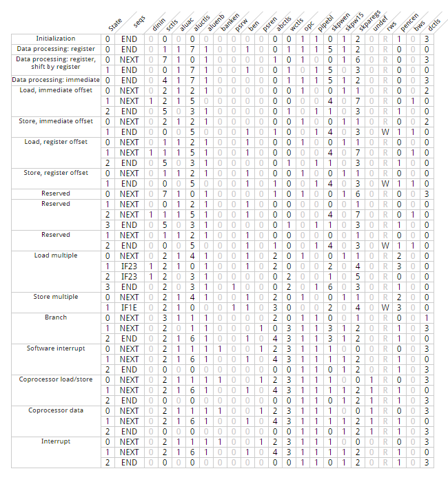
Since the raw PLA output is fairly meaningless, I have broken it down into fields and done a small amount of decoding. The image below shows the decoded contents of the instruction decode PLA; click for full-size. Each row corresponds to one clock cycle in an instruction and each column is one of the 22 fields generated by the 36 bits of the PLA. The PLA handles 18 different instruction groups, indicated on the left.
The rows Initialization and Interrupt are not instructions per se, but triggered by other PLA inputs. The Initialization micro-instruction is an idle step used when the pipeline does not have a valid instruction (at startup or after R15 modification). It is triggered if the iregval signal (8156) from the Pipeline State circuit is 0. The Interrupt microinstructions handle an interrupt or fault and are triggered by the intseq signal (8118) from the Trap Control circuit. The Reserved rows correspond to undocumented instructions, probably load and store with register-specified shift. The first Reserved row is unique in that the microcode sequence forks; this is cycle number 0 for both of the next Reserved blocks. It is unclear why these instructions were implemented but not documented.
Example microinstructions
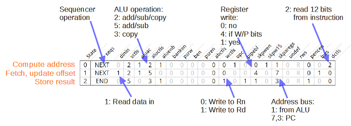
The diagram below illustrates the three microinstructions that make up the load register immediate (LDR) instruction, with explanations on some of the important fields. The first microinstruction computes the address: the indicated fields instruct the ALU to add or subtract the 12-bit offset value from the instruction, and put the value on the address bus. The ALU control logic uses the U (up/down) and P (pre/posts) bits in the instruction to determine if the offset should be added or subtracted or ignored. This illustrates that the microinstruction only partially defines the instruction; the hardcoded control logic also makes decisions based on the instruction. The microinstruction also specifies that the sequencer should move to the next microinstruction.
The next microinstruction instructs the ALU to update the offset register. As before, the ALU control logic determines if the update requires an add or subtract. The register control logic determines if the register should be updated. The microinstruction also indicates that the fetched data should be read in.
The final microinstruction stores the fetched result in a register. It specifies Rd as the destination register and indicates a register write. The microinstruction tells the sequencer this is the end of the instruction.
Fields in the microinstruction
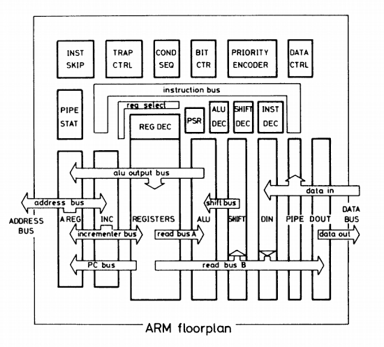
This section describes the fields that make up the microinstruction. I am still working out all the details, so this is not 100% accurate. Refer to the floorplan diagram below to see the components involved.
seqs: sequencer control
This field specifies the cycle number for the next microinstruction. It is used by the Sequence Controller. It has the following values:
| Field | Label | Meaning |
|---|---|---|
| 0 | END | End of the instruction |
| 1 | NEXT | Move to next cycle in sequence |
| 2 | IF23 | If not pencz, next cycle is 2; if pencz, next cycle is 3. |
| 3 | IF1E | If not pencz, next cycle is 1; if pencz, ends the instruction. |
The pencz signal from the priority encoder indicates all registers have been processed for a LDM/STM instruction.
For more information, see Reverse engineering ARM1 instruction sequencing.
Signal numbers: 8310, 8309. I've put this field first to make control flow clearer, but it is physically after rws in the PLA.
dinin: data in to B bus
This field indicates the value on the data pins should be read in to the B bus. It is used by the data bus controls.Signal number: 8111
sctls: shifter controls
This field specifies the shifter action at a high level. The Shift Decode block uses this field in combination with other instruction bits and values to determine the specific shift direction and amount.
| Field | Shifter action |
|---|---|
| 0 | Rs |
| 1 | DP instruction |
| 2 | ASL 2*instruction |
| 3 | byte to word |
| 4 | no shift |
| 5 | ASL 2 bits |
| 6 | nop (unused) |
| 7 | nop |
For more details, see Decoding barrel-shifter commands.
Signal numbers: 8288, 8287, 8286. Note that bits 2 and 1 are reversed coming out of the PLA.
aluac: ALU latch A bus
This signal latches the A bus value as an ALU input. The ALU control logic generates latch controls 2370, 2371 from this signal. For more details, see The ALU control logic.Signal number: 8058
aluctls: ALU mode controls
This field selects the ALU mode. The ALU decoder uses this field to generate the ALU control signals.
| Field | Operation | Instructions |
|---|---|---|
| 0 | add/rsb for base register update / address | LDM/STM/Data processing |
| 1 | add for branch/fault destination | B/SWI |
| 2 | add/sub/nop for address computation | LDR/STR |
| 3 | mov for register update, nop for abort | LDM/LDR |
| 4 | add/rsb/mov for address computation | LDM/STM |
| 5 | add/sub for base register update | LDR/STR |
| 6 | rsb for link address update | BL / SWI |
| 7 | op specified by instruction | Data processing |
For more details, see The ALU control logic.
Signal numbers: 8062, 8061, 8060
aluenb: ALU latch B bus
This signal latches the B bus value as an ALU input. The ALU control logic generates latch controls 7485, 7486 from this signal. For more details, see The ALU control logic.Signal number: 8063
banken: update PSR mode
This signal causes the M0, M1, F and I flags in the PSR to be updated from the psrbank signals from the trap control circuit. This happens during fault handling. This signal is used by the flag circuitry. For more details, see The ARM1 processor's flags.Signal number: 8075
psrw: PSR write
This signal indicates that the PSR is potentially being written by a LDM/STM block copy instruction. It controls writing the ALU bus to the flags, after some more logic. It also allows LDM/STM to access the user-mode registers via the S bit. This signal is used by the flag circuitry. For more details, see The ARM1 processor's flags.Signal number: 8273
nben: data to B bus
This signal indicates that the register file should write to the B bus when nben is 0. This signal is used by the register control logic and the flag logic. For more details, see The ARM1 processor's flags and Inside the ARMv1 Register Bank.Signal number: 8186; the signal is negative-active.
psren: PSR to B bus
When active, this signal enables writing the PSR to the B bus to save it during a trap. This signal is used by the flag logic. For more details, see The ARM1 processor's flags.Signal number: 8272
abctls: register controls for A and B bus
This field controls which registers are read onto the A and B bus. This signal is used by the register control logic.
| Field | A register selector | B register selector |
|---|---|---|
| 0 | Instruction bits 16-19 (Rn) | Instruction bits 0-3 (Rm) |
| 1 | Instruction bits 8-11 (Rs) | Instruction bits 12-15 (Rd) |
| 2 | R15 | Instruction bits 16-19 (Rn) |
| 3 | R15 | From priority encoder |
| 4 | Instruction bits 16-19 (Rn) | R14 |
For more details, see Inside the ARMv1 Register Bank — register selection.
Signal numbers: 8042, 8041, 8040
wctls: register write controls
This field selects which register gets written to, from the ALU bus. This signal is used by the register control logic.
| Field | Register selector |
|---|---|
| 0 | Instruction bits 16-19 (Rn) |
| 1 | Instruction bits 12-15 (Rd) |
| 2 | From priority encoder |
| 3 | R14 (link) |
For more details, see Inside the ARMv1 Register Bank — register selection.
Signal numbers: 8356, 8355
opc: OPC opcode fetch signal
This signal goes to the OPC pin and indicates a new instruction is being fetched. It is also used by the pipeline state circuitry.Signal number: 8630
pipebl: pipeline control
This signal is used by the pipeline state circuitry. It apparently indicates the end of the instruction, except for STM. It is high throughout branches and faults, perhaps to clear the pipeline.Signal number: 8261
skpwen: register write enable controls
This field controls whether a write to the register file happens or not. It is used by the Instruction Skip circuitry which can block the write if the instruction is aborted. The following table is a rough draft.
| Field | Write condition |
|---|---|
| 0 | None |
| 1 | Not dataabort |
| 2 | Writeback |
| 3 | Instruction bit 24 (link) |
| 4 | Writeback / P bit |
| 5 | alureg |
| 6 | skpawen0 |
Signal numbers: 8324, 8323, 8322
skpw15: register 15 write controls
This signal controls writes to the R15 (PC). It is used by the Instruction Skip circuitry, perhaps to clear the pipeline when R15 is updated.Signal number: 8321
skparegs: address bus controls
This field controls what is written to the address bus. It is used by the Instruction Skip circuitry to generate the address bus controls. The following table is a rough draft.
| Field | Address source |
|---|---|
| 0 | Trap address |
| 1 | ALU bus |
| 2 | incrementer (normal) or ALU bus (for R15 write) |
| 3 | unincremented PC (normal) or ALU bus (for R15 write) |
| 4 | ALU bus or PC or incrementer, depending on R15 write and priority encoder |
| 5 | ALU bus or PC or incrementer, depending on R15 write and priority encoder |
| 6 | incrementer |
| 7 | unincremented PC (normal) or ALU bus (for R15 write) |
For more details, see Inside the ARMv1 — the Read Bus B, ALU Output Bus, and Address Bus.
Signal numbers: 8320, 8319, 8318
undef: undefined instruction
This signal is generated for an undefined instruction (specifically a coprocessor instruction). It is used by the Trap Control circuitry to generate a fault.Signal number: 8348
rws: read or write select
This signal controls the RW output; it is 1 for a read and 0 for a write. The Trap Control circuitry gates this (apparently to block writes on an address exception) and the signal then drives the RW pin.Signal number: 8284
pencen: priority encoder A bus control
This field controls writing of the bit counter output (times 4) to the A bus. It can also set the two low bits, either for the constant 3, or to add 3 to the bit counter output. The constant 3 is used (with borrow) to subtract 4 from R14 during a branch with link, see page 233 of VLSI RISC Architecture and Organization. The modified bit counter output is used to compute the LDM/STM start address.
| Field | Bit counter action on A bus |
|---|---|
| 0 | None |
| 1 | Low bits set (3) |
| 2 | Bit count |
| 3 | Bit count, low bits set |
Signal numbers: 8202, 8201
bws: enable byte/word select
This signal indicates that byte/word should be selected by instruction bit 22, for LDR/STR. This signal is used by the Data Control (field extraction) circuitry.For more details, see Inside the ARMv1 Read Bus.
Signal number: 8082
dctls: data bus field extraction controls
This field controls which bits of the data bus or instruction are passed to the B bus. This field is used by the Data Control (field extraction) circuitry.
| Field | Selected data bus field |
|---|---|
| 0 | Select a byte or word depending on bw |
| 1 | 24 bits (branch offset) |
| 2 | 12 bits (LDR/STR offset) |
| 3 | byte (immediate instr) |
For field 0, the byte is specified by controls 8195 and 8194.
For more details, see Inside the ARMv1 Read Bus or pages 296 and 301 of VLSI Risc Architecture and Organization.
Signal numbers: 8105, 8104
Microcode in RISC?
Everyone "knows" that RISC processors don't use microcode.[3] So does the ARM1 have "real microcode"?One of the ARM1 architects explains microcode: "A microcode address is formed from some or all of the contents of the instruction register, together with some state values which are internal to the micro-control unit. This address is decoded to drive a unique row of a matrix, the columns of which are the control signals for the datapath."[4] This description is a perfect fit for how the ARM1's control works, so it seems reasonable to consider the ARM1 to have microcode.
I think it's easiest to understand the ARM1's control logic by viewing it as microcode. However, there are couple reasons to consider it not "real microcode". One reason is that the ARM1 microcode is only a small part of the chip's control, as you can see in the die photo and floorplan earlier. The control signals are heavily modified by the instruction skip component and conditionals are handled by the conditional unit. This goes beyond vertical microcode, where logic expands the microcode's control signals; in the ARM1, this other circuitry can entirely override the control signals. In addition, the ARM1 uses separate circuitry (the priority encoder) to control the block data transfer instructions; the microcode just sits in a loop. (The ARM2 is similar with multiplication — a separate circuit controls multiplication.)
The ARM1's microcode is an order of magnitude smaller than other microcoded processors. The ARM1's microcode has a 42×36 microcode, for 1512 bits in total. The 8086 used a 504×21 microcode (over 10,000 bits) while the 68000 has a 544×17 microcode and 366×68 nanocode (over 34,000 bits).
Probably the biggest objection to calling the ARM1 microcoded is that the designers of the ARM chip didn't consider it that way.[4] Furber mentions that some commercial RISC processors use microcode, but doesn't apply that term to the ARM1. He describes ARM1's instruction decode as two-level structure. In the first level, the instruction decoder PLA differentiates instructions into classes with similar characteristics. The secondary decoding uses the information from the first level along with hardware to cope with all the possible operations. The first level is described as providing "broad hints" about which functions to choose, and the second level fills in the details with bits from the instruction.
Conclusion
So is the ARM1 microcoded or not? The instruction decoder is clearly made up of microinstructions executed sequentially or with branching. It makes sense to look at this as microcode. But on the other hand, the microcode is fairly simple and forms a small part of the total control circuitry. A large amount of hardcoded logic interprets the microinstruction outputs to generate the control signals. My conclusion is the ARM1 should be called "partially microcoded" or maybe "hybrid microcode / hardwired control".This article owes a lot to Dave Mugridge's analysis of the ARM1, especially Inside the ARMv1 — instruction decoding and sequencing. Thanks to the Visual 6502 team for the ARM1 simulator and data used in my analysis.
Notes and references
[1] While a typical PLA acts as structured logic gates generating signals (as in the Z-80 or 6502), the ARM1's PLA is different. Exactly one row is active at a time, so the PLA functions more like a ROM. There's a discussion of ROMs as PLAs in section 7.3.2.2 of The Architecture of Microprocessors.[2] My explanation of the LDR instruction is simplified, since the instruction provides a variety of addressing mechanisms. It also provides byte access as well as 32-bit word access. Full details are here.
[3] IBM's ROMP microprocessor is generally considered RISC, but uses a 256×34 control ROM. Likewise, the Intel i960 is usually considered RISC but uses microcode.
[4] ARM1 designer Furber's book VLSI RISC Architecture and Organization discusses the ARM1 and other RISC chips. Section 1.3.1 has an extensive discussion of microcode. He describes how the ARM1's block move and ARM2's multiplication operations are under the control of a separate hardware unit inside the chip, unlike how a microcoded implementation would operate. Section 4.7 describes the ARM1's control logic.


I suppose this "microcode" is used in the execute pipeline stage while the fetch and decode stages are hardwired (other than using the opc and pipebl signals generated here).
ReplyDeleteThx my friend!
ReplyDelete