Switching power supplies are now very cheap, but this wasn't always the case. In the 1950s, switching power supplies were complex and expensive, used in aerospace and satellite applications that needed small, lightweight power supplies. By the early 1970s, new high-voltage transistors and other technology improvements made switching power supplies much cheaper and they became widely used in computers.[2] The introduction of a single-chip power supply controller in 1976 made switching power supplies simpler, smaller, and cheaper.
Apple's involvement with switching power supplies goes back to 1977 when Apple's chief engineer Rod Holt designed a switching power supply for the Apple II. According to Steve Jobs:[3]
"That switching power supply was as revolutionary as the Apple II logic board was. Rod doesn't get a lot of credit for this in the history books but he should. Every computer now uses switching power supplies, and they all rip off Rod Holt's design."
This is a fantastic quote, but unfortunately it is entirely false. The switching power supply revolution happened before Apple came along, Apple's design was similar to earlier power supplies[4] and other computers don't use Rod Holt's design. Nevertheless, Apple has extensively used switching power supplies and pushes the limits of charger design with their compact, stylish and advanced chargers.
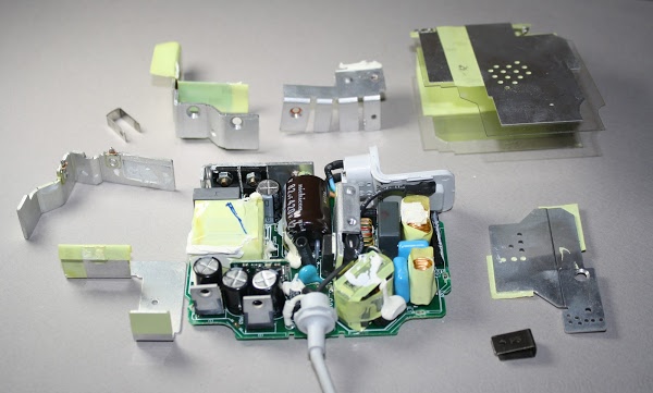
Inside the charger
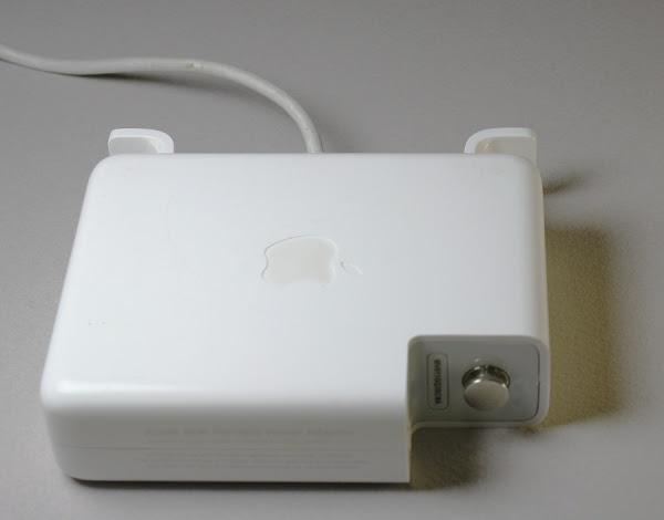
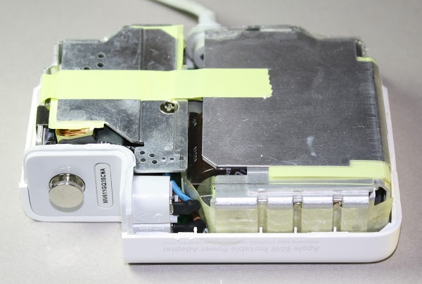
For the teardown I started with a Macbook 85W power supply, model A1172, which is small enough to hold in your palm. The picture below shows several features that can help distinguish the charger from counterfeits: the Apple logo in the case, the metal (not plastic) ground pin on the right, and the serial number next to the ground pin.
AC enters the charger
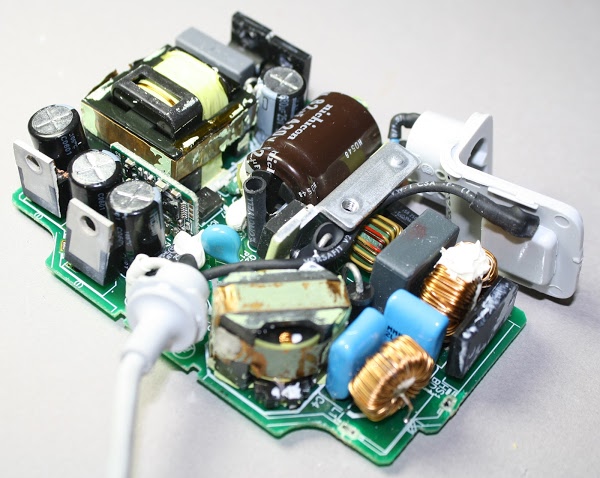
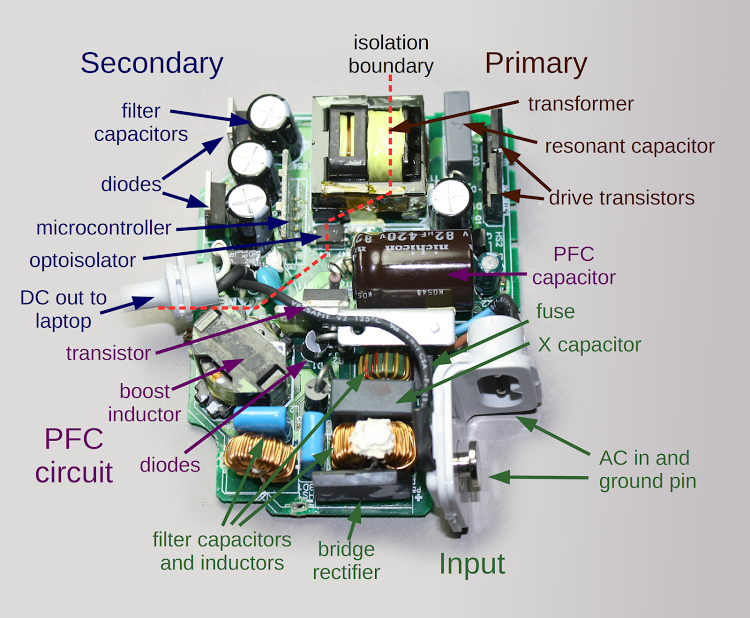
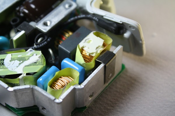
AC power enters the charger through a removable AC plug. A big advantage of switching power supplies is they can be designed to run on a wide range of input voltages. By simply swapping the plug, the charger can be used in any region of the world, from European 240 volts at 50 Hertz to North American 120 volts at 60 Hz. The filter capacitors and inductors in the input stage prevent interference from exiting the charger through the power lines. The bridge rectifier contains four diodes, which convert the AC power into DC. (See this video for a great demonstration of how a full bridge rectifier works.)
PFC: smoothing the power usage
The next step in the charger's operation is the Power Factor Correction circuit (PFC), labeled in purple. One problem with simple chargers is they only draw power during a small part of the AC cycle.[5] If too many devices do this, it causes problems for the power company. Regulations require larger chargers to use a technique called power factor correction so they use power more evenly.
The PFC circuit uses a power transistor to precisely chop up the input AC tens of thousands of times a second; contrary to what you might expect, this makes the load on the AC line smoother. Two of the largest components in the charger are the inductor and PFC capacitor that help boost the voltage to about 380 volts DC.[6]
The primary: chopping up the power
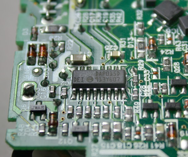
The primary circuit is the heart of the charger. It takes the high voltage DC from the PFC circuit, chops it up and feeds it into the transformer to generate the charger's low-voltage output (16.5-18.5 volts). The charger uses an advanced design called a resonant controller, which lets the system operate at a very high frequency, up to 500 kilohertz. The higher frequency permits smaller components to be used for a more compact charger. The chip below controls the switching power supply.[7]
The two drive transistors (in the overview diagram) alternately switch on and off to chop up the input voltage. The transformer and capacitor resonate at this frequency, smoothing the chopped-up input into a sine wave.
The secondary: smooth, clean power output
The secondary side of the circuit generates the output of the charger. The secondary receives power from the transformer and converts it DC with diodes. The filter capacitors smooth out the power, which leaves the charger through the output cable.
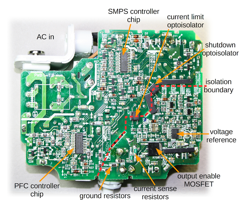
The most important role of the secondary is to keep the dangerous high voltages in the rest of the charger away from the output, to avoid potentially fatal shocks. The isolation boundary marked in red on the earlier diagram indicates the separation between the high-voltage primary and the low-voltage secondary. The two sides are separated by a distance of about 6 mm, and only special components can cross this boundary.
The transformer safely transmits power between the primary and the secondary by using magnetic fields instead of a direct electrical connection. The coils of wire inside the transformer are triple-insulated for safety. Cheap counterfeit chargers usually skimp on the insulation, posing a safety hazard. The optoisolator uses an internal beam of light to transmit a feedback signal between the secondary and primary. The control chip on the primary side uses this feedback signal to adjust the switching frequency to keep the output voltage stable.
A powerful microprocessor in your charger?
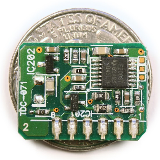
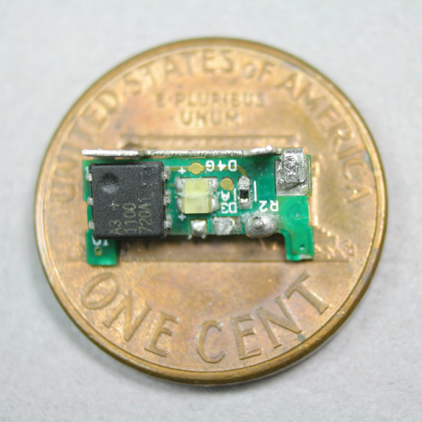
One unexpected component is a tiny circuit board with a microcontroller, which can be seen above. This 16-bit processor constantly monitors the charger's voltage and current. It enables the output when the charger is connected to a Macbook, disables the output when the charger is disconnected, and shuts the charger off if there is a problem. This processor is a Texas Instruments MSP430 microcontroller, roughly as powerful as the processor inside the original Macintosh.[8]
The square orange pads on the right are used to program software into the chip's flash memory during manufacturing.[9] The three-pin chip on the left (IC202) reduces the charger's 16.5 volts to the 3.3 volts required by the processor.[10]
The charger's underside: many tiny components
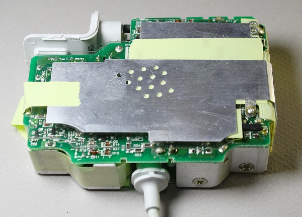
Turning the charger over reveals dozens of tiny components on the circuit board. The PFC controller chip and the power supply (SMPS) controller chip are the main integrated circuits controlling the charger. The voltage reference chip is responsible for keeping the voltage stable even as the temperature changes.[11] These chips are surrounded by tiny resistors, capacitors, diodes and other components. The output MOSFET transistor switches the power to the output on and off, as directed by the microcontroller. To the left of it, the current sense resistors measure the current flowing to the laptop.
One reason the charger has more control components than a typical charger is its variable output voltage. To produce 60 watts, the charger provides 16.5 volts at 3.6 amps. For 85 watts, the voltage increases to 18.5 volts at 4.6 amps. This allows the charger to be compatible with lower-voltage 60 watt chargers, while still providing 85 watts for laptops that can use it.[13] As the current increases above 3.6 amps, the circuit gradually increases the output voltage. If the current increases too much, the charger abruptly shuts down around 90 watts.[14]
Inside the Magsafe connector
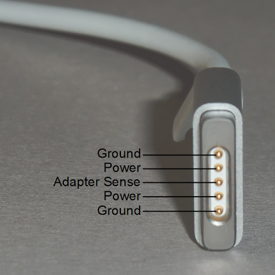
The magnetic Magsafe connector that plugs into the Macbook is more complex than you would expect. It has five spring-loaded pins (known as Pogo pins) to connect to the laptop. Two pins are power, two pins are ground, and the middle pin is a data connection to the laptop.
Operation of the charger
You may have noticed that when you plug the connector into a Macbook, it takes a second or two for the LED to light up. During this time, there are complex interactions between the Macbook, the charger, and the Magsafe connector.When the charger is disconnected from the laptop, the output transistor discussed earlier blocks the output power.[15] When the Magsafe connector is plugged into a Macbook, the laptop pulls the power line low.[16] The microcontroller in the charger detects this and after exactly one second enables the power output. The laptop then loads the charger information from the Magsafe connector chip. If all is well, the laptop starts pulling power from the charger and sends a command through the data pin to light the appropriate connector LED. When the Magsafe connector is unplugged from the laptop, the microcontroller detects the loss of current flow and shuts off the power, which also extinguishes the LEDs.
You might wonder why the Apple charger has all this complexity. Other laptop chargers simply provide 16 volts and when you plug it in, the computer uses the power. The main reason is for safety, to ensure that power isn't flowing until the connector is firmly attached to the laptop. This minimizes the risk of sparks or arcing while the Magsafe connector is being put into position.
Why you shouldn't get a cheap charger
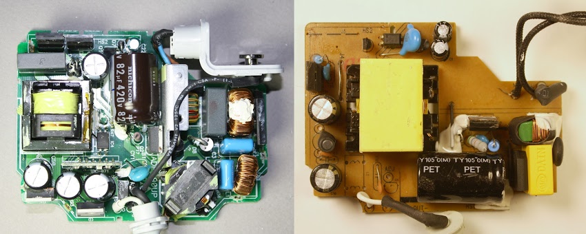
The Macbook 85W charger costs $79 from Apple, but for $14 you can get a charger on eBay that looks identical. Do you get anything for the extra $65? I opened up an imitation Macbook charger to see how it compares with the genuine charger. From the outside, the charger looks just like an 85W Apple charger except it lacks the Apple name and logo. But looking inside reveals big differences. The photos below show the genuine Apple charger on the left and the imitation on the right.
The imitation charger has about half the components of the genuine charger and a lot of blank space on the circuit board. While the genuine Apple charger is crammed full of components, the imitation leaves out a lot of filtering and regulation as well as the entire PFC circuit. The transformer in the imitation charger (big yellow rectangle) is much bulkier than in Apple's charger; the higher frequency of Apple's more advanced resonant converter allows a smaller transformer to be used.
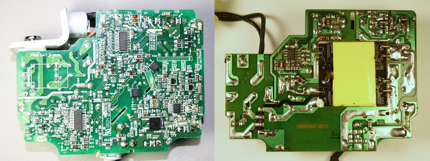
Flipping the chargers over and looking at the circuit boards shows the much more complex circuitry of the Apple charger. The imitation charger has just one control IC (in the upper left).[17] since the PFC circuit is omitted entirely. In addition, the control circuits are much less complex and the imitation leaves out the ground connection.
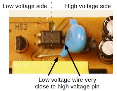
The imitation charger is actually better quality than I expected, compared to the awful counterfeit iPad charger and iPhone charger that I examined. The imitation Macbook charger didn't cut every corner possible and uses a moderately complex circuit. The imitation charger pays attention to safety, using insulating tape and keeping low and high voltages widely separated, except for one dangerous assembly error that can be seen below. The Y capacitor (blue) was installed crooked, so its connection lead from the low-voltage side ended up dangerously close to a pin on the high-voltage side of the optoisolator (black), creating a risk of shock.
Problems with Apple's chargers
The ironic thing about the Apple Macbook charger is that despite its complexity and attention to detail, it's not a reliable charger. When I told people I was doing a charger teardown, I rapidly collected a pile of broken chargers from people who had failed chargers. The charger cable is rather flimsy, leading to a class action lawsuit stating that the power adapter dangerously frays, sparks and prematurely fails to work. Apple provides detailed instructions on how to avoid damaging the wire, but a stronger cable would be a better solution. The result is reviews on the Apple website give the charger a dismal 1.5 out of 5 stars.
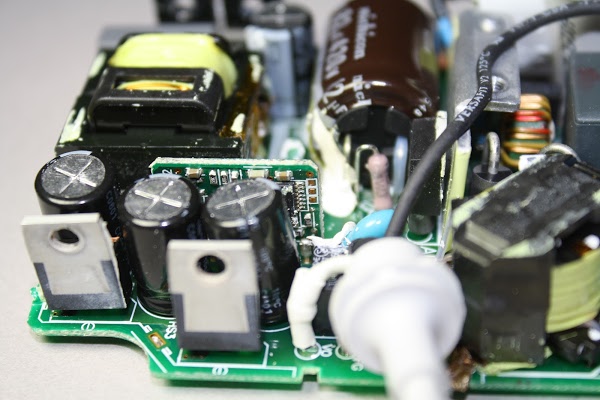
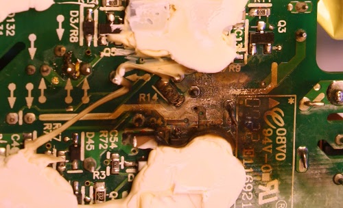
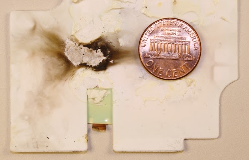
Macbook chargers also fail due to internal problems. The photos above and below show burn marks inside a failed Apple charger from my collection.[18] I can't tell exactly what went wrong, but something caused a short circuit that burnt up a few components. (The white gunk in the photo is insulating silicone used to mount the board.)
Why Apple's chargers are so expensive
As you can see, the genuine Apple charger has a much more advanced design than the imitation charger and includes more safety features. However, the genuine charger costs $65 more and I doubt the additional components cost more than $10 to $15[19]. Most of the cost of the charger goes into the healthy profit margin that Apple has on their products. Apple has an estimated 45% profit margin on iPhones[20] and chargers are probably even more profitable. Despite this, I don't recommend saving money with a cheap eBay charger due to the safety risk.
Conclusion
People don't give much thought to what's inside a charger, but a lot of interesting circuitry is crammed inside. The charger uses advanced techniques such as power factor correction and a resonant switching power supply to produce 85 watts of power in a compact, efficient unit. The Macbook charger is an impressive piece of engineering, even if it's not as reliable as you'd hope. On the other hand, cheap no-name chargers cut corners and often have safety issues, making them risky, both to you and your computer.Notes and references
[1] The main alternative to a switching power supply is a linear power supply, which is much simpler and converts excess voltage to heat. Because of this wasted energy, linear power supplies are only about 60% efficient, compared to about 85% for a switching power supply. Linear power supplies also use a bulky transformer that may weigh multiple pounds, while switching power supplies can use a tiny high-frequency transformer.[2] Switching power supplies were taking over the computer industry as early as 1971. Electronics World said that companies using switching regulators "read like a 'Who's Who' of the computer industry: IBM, Honeywell, Univac, DEC, Burroughs, and RCA, to name a few". See "The Switching Regulator Power Supply", Electronics World v86 October 1971, p43-47. In 1976, Silicon General introduced SG1524 PWM integrated circuit, which put the control circuitry for a switching power supply on a single chip.
[3] The quote about the Apple II power supply is from page 74 of the 2011 book Steve Jobs by Walter Isaacson. It inspired me to write a detailed history of switching power supplies: Apple didn't revolutionize power supplies; new transistors did. Steve Job's quote sounds convincing, but I consider it the reality distortion field in effect.
[4] If anyone can take the credit for making switching power supplies an inexpensive everyday product, it is Robert Boschert. He started selling switching power supplies in 1974 for everything from printers and computers to the F-14 fighter plane. See Robert Boschert: A Man Of Many Hats Changes The World Of Power Supplies in Electronic Design. The Apple II's power supply is very similar to the Boschert OL25 flyback power supply but with a patented variation.
[5] You might expect the bad power factor is because switching power supplies rapidly turn on and off, but that's not the problem. The difficulty comes from the nonlinear diode bridge, which charges the input capacitor only at peaks of the AC signal. (If you're familiar with power factors due to phase shift, this is totally different. The problem is the non-sinusoidal current, not a phase shift.)
The idea behind PFC is to use a DC-DC boost converter before the switching power supply itself. The boost converter is carefully controlled so its input current is a sinusoid proportional to the AC waveform. The result is the boost converter looks like a nice resistive load to the power line, and the boost converter supplies steady voltage to the switching power supply components.
[6] The charger uses a MC33368 "High Voltage GreenLine Power Factor Controller" chip to run the PFC. The chip is designed for low power, high-density applications so it's a good match for the charger.
[7] The SMPS controller chip is a L6599 high-voltage resonant controller; for some reason it is labeled DAP015D. It uses a resonant half-bridge topology; in a half-bridge circuit, two transistors control power through the transformer first one direction and then the other. Common switching power supplies use a PWM (pulse width modulation) controller, which adjusts the time the input is on. The L6599, on the other hand, adjusts the frequency instead of the pulse width. The two transistors alternate switching on for 50% of the time. As the frequency increases above the resonant frequency, the power drops, so controlling the frequency regulates the output voltage.
[8] The processor in the charger is a MSP430F2003 ultra low power microcontroller with 1kB of flash and just 128 bytes of RAM. It includes a high-precision 16-bit analog to digital converter. More information is here.
The 68000 microprocessor from the original Apple Macintosh and the 430 microcontroller in the charger aren't directly comparable as they have very different designs and instruction sets. But for a rough comparison, the 68000 is a 16/32 bit processor running at 7.8MHz, while the MSP430 is a 16 bit processor running at 16MHz. The Dhrystone benchmark measures 1.4 MIPS (million instructions per second) for the 68000 and much higher performance of 4.6 MIPS for the MSP430. The MSP430 is designed for low power consumption, using about 1% of the power of the 68000.
[9] The 60W Macbook charger uses a custom MSP430 processor, but the 85W charger uses a general-purpose processor that needs to loaded with firmware. The chip is programmed with the Spy-Bi-Wire interface, which is TI's two-wire variant of the standard JTAG interface. After programming, a security fuse inside the chip is blown to prevent anyone from reading or modifying the firmware.
[10] The voltage to the processor is provided by not by a standard voltage regulator, but a LT1460 precision reference, which outputs 3.3 volts with the exceptionally high accuracy of 0.075%. This seems like overkill to me; this chip is the second-most expensive chip in the charger after the SMPS controller, based on Octopart's prices.
[11] The voltage reference chip is unusual, it is a TSM103/A that combines two op amps and a 2.5V reference in a single chip. Semiconductor properties vary widely with temperature, so keeping the voltage stable isn't straightforward. A clever circuit called a bandgap reference cancels out temperature variations; I explain it in detail here.
[12] Since some readers are very interested in grounding, I'll give more details. A 1KΩ ground resistor connects the AC ground pin to the charger's output ground. (With the 2-pin plug, the AC ground pin is not connected.) Four 9.1MΩ resistors connect the internal DC ground to the output ground. Since they cross the isolation boundary, safety is an issue. Their high resistance avoids a shock hazard. In addition, since there are four resistors in series for redundancy, the charger remains safe even if a resistor shorts out somehow. There is also a Y capacitor (680pF, 250V) between the internal ground and output ground; this blue capacitor is on the upper side of the board. A T5A fuse (5 amps) protects the output ground.
[13] The power in watts is simply the volts multiplied by the amps. Increasing the voltage is beneficial because it allows higher wattage; the maximum current is limited by the wire size.
[14] The control circuitry is fairly complex. The output voltage is monitored by an op amp in the TSM103/A chip which compares it with a reference voltage generated by the same chip. This amplifier sends a feedback signal via an optoisolator to the SMPS control chip on the primary side. If the voltage is too high, the feedback signal lowers the voltage and vice versa. That part is normal for a power supply, but ramping the voltage from 16.5 volts to 18.5 volts is where things get complicated.
The output current creates a voltage across the current sense resistors, which have a tiny resistance of 0.005Ω each - they are more like wires than resistors. An op amp in the TSM103/A chip amplifies this voltage. This signal goes to tiny TS321 op amp which starts ramping up when the signal corresponds to 4.1A. This signal goes into the previously-described monitoring circuit, increasing the output voltage.
The current signal also goes into a tiny TS391 comparator, which sends a signal to the primary through another optoisolator to cut the output voltage. This appears to be a protection circuit if the current gets too high. The circuit board has a few spots where zero-ohm resistors (i.e. jumpers) can be installed to change the op amp's amplification. This allows the amplification to be adjusted for accuracy during manufacture.
[15] If you measure the voltage from a Macbook charger, you'll find about six volts instead of the 16.5 volts you'd expect. The reason is the output is deactivated and you're only measuring the voltage through the bypass resistor just below the output transistor.
[16] The laptop pulls the charger output low with a 39.41KΩ resistor to indicate that it is ready for power. An interesting thing is it won't work to pull the output too low - shorting the output to ground doesn't work. This provides a safety feature. Accidental contact with the pins is unlikely to pull the output to the right level, so the charger is unlikely to energize except when properly connected.
[17] The imitation charger uses the Fairchild FAN7602 Green PWM Controller chip, which is more advanced than I expected in a knock-off; I wouldn't have been surprised if it just used a simple transistor oscillator. Another thing to note is the imitation charger uses a single-sided circuit board, while the genuine uses a double-sided circuit board, due to the much more complex circuit.
[18] The burnt charger is an Apple A1222 85W Macbook charger, which is a different model from the A1172 charger in the rest of the teardown. The A1222 is in a slightly smaller, square case and has a totally different design based on the NCP 1203 PWM controller chip. Components in the A1222 charger are packed even more tightly than in the A1172 charger. Based on the burnt-up charger, I think they pushed the density a bit too far.
[19] I looked up many of the charger components on Octopart to see their prices. Apple's prices should be considerably lower. The charger has many tiny resistors, capacitors and transistors; they cost less than a cent each. The larger power semiconductors, capacitors and inductors cost considerably more. I was surprised that the 16-bit MSP430 processor costs only about $0.45. I estimated the price of the custom transformers. The list below shows the main components.
| Component | Cost | |
|---|---|---|
| MSP430F2003 processor | $0.45 | |
| MC33368D PFC chip | $0.50 | |
| L6599 controller chip | $1.62 | |
| LT1460 3.3V reference | $1.46 | |
| TSM103/A reference | $0.16 | |
| 2x P11NM60AFP 11A 600V MOSFET | $2.00 | |
| 3x Vishay optocoupler | $0.48 | |
| 2x 630V 0.47uF film capacitor | $0.88 | |
| 4x 25V 680uF electrolytic capacitor | $0.12 | |
| 420V 82uF electrolytic capacitor | $0.93 | |
| polypropylene X2 capacitor | $0.17 | |
| 3x toroidal inductor | $0.75 | |
| 4A 600V diode bridge | $0.40 | |
| 2x dual common-cathode schottky rectifier 60V, 15A | $0.80 | |
| 20NC603 power MOSFET | $1.57 | |
| transformer | $1.50? | |
| PFC inductor | $1.50? |
[20] The article Breaking down the full $650 cost of the iPhone 5 describes Apple's profit margins in detail, estimating 45% profit margin on the iPhone. Some people have suggested that Apple's research and development expenses explain the high cost of their chargers, but the math shows R&D costs must be negligible. The book Practical Switching Power Supply Design estimates 9 worker-months to design and perfect a switching power supply, so perhaps $200,000 of engineering cost. More than 20 million Macbooks are sold per year, so the R&D cost per charger would be one cent. Even assuming the Macbook charger requires ten times the development of a standard power supply only increases the cost to 10 cents.
