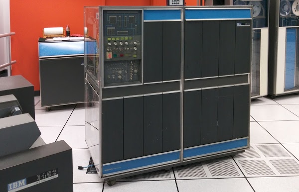
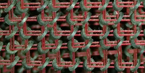
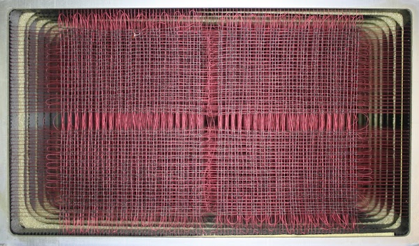
The IBM 1401 was low-end business computer that became the most popular computer of the early 1960s due to its low cost: $2500 a month, Like most computers of its era it uses ferrite core memory, which stores bits on tiny magnetized rings. The photo below shows a closeup of the ferrite cores, strung on red wires.
The 1401 had only 4,000 characters of storage internally, but could hold 16,000 characters with the addition of the IBM 1406 Storage Unit. This core memory expansion unit was about the size of a dishwasher and was connected to the 1401 computer by two thick cables.[1] This 12,000 character expansion box could be leased for $1575 a month or purchased for $55,100. (In comparison, a new house in San Francisco was about $27,000 at the time.) The failing memory locations were all in the same 4K block in the IBM 1406, which helped narrow down the problem.
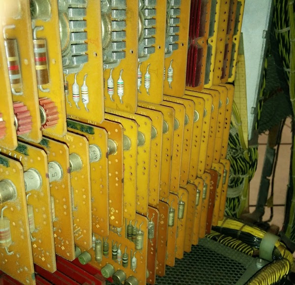
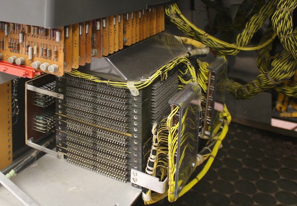
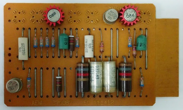
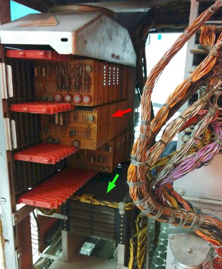
The circuits in the 1406 (and the 1401) are made up of Standardized Module System (SMS) cards. A typical card has a few transistors and implements a logic gate or two. Unlike modern transistors, these transistors are made from germanium, not silicon. The photo below shows rows of SMS cards inside the 1406. Note the metal heat sinks on the high-current transistors driving the core module.
The IBM 1401 predates 8-bit bytes, and it used 6-bit characters. Each character consisted of a 4-bit BCD (binary-coded decimal) digit along with two extra "zone" bits. By setting zone bits, letters and a few symbols could be stored. For instance, with both zone bits set, the BCD digit values 1 through 9 corresponded to the characters "A" through "I". Other zone bit combinations provided the rest of the alphabet. While this encoding may seem strange, it maps directly onto IBM punched cards, which have 10 rows for the digit and two rows for zone punches. This encoding was called BCDIC (Binary-Coded Decimal Interchange Code), and later became the much-derided EBCDIC (Extended BCDIC) encoding. (You may have noticed that 8 planes are used for 6-bit characters. One extra plane holds special "word mark" bits, and the other holds parity.)
The point of this digression into IBM character encoding is that a three-digit address also included 6 zone bits. Four of these bits were used as part of the address, allowing 16,000 addresses in total.[2] For example, the address 14,578 would be represented as the digits 578 along with the appropriate zone bits, so the resulting address would be represented as the three characters "N7H".[3]
Getting back to the problem with the memory unit, the 4K bank was failing with addresses ending in 2, 4 and 6. Looking at 2, 4 and 6, I immediately concluded that what these all had in common was the 2 bit was set. Except 4 doesn't have the 2 bit set. So maybe the problem was with even addresses. Except 0 and 8 worked. After staring at bit patterns a while, I became puzzled because 2, 4 and 6 didn't really have anything in common.
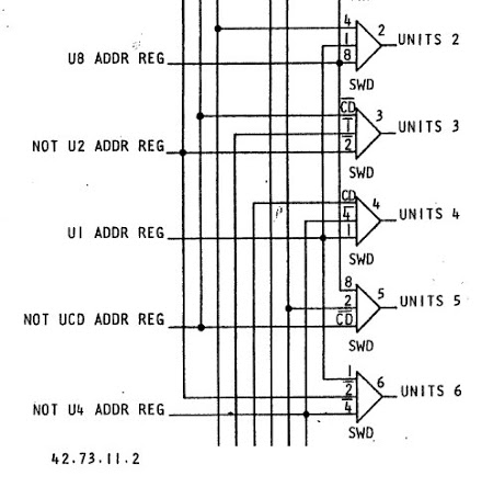
Looking at the logic diagrams reveals the hardware optimization that makes 2, 4, and 6 have something in common. Since the problem happened with specific unit digits, the problem was most likely in the address decoding circuitry that translates the unit digit to a particular select line.[4] The normal way of decoding a digit is to look at the 4 bits of the digit to determine the value. Unexpectedly, the decoder only looks at 3 bits; this reduces the hardware required, saving money. For instance, the digit 2 is detected below if the 4 bit is clear, the 1 bit is clear, and the 8 bit is clear. The digit 4 is detected if the parity (CD) bit is clear, the 4 bit is set, and the 1 bit is clear. The digit 6 is detected if the 1 bit is clear, the 2 bit is set, and the 4 bit is set.[5] Looking at the decode logic, decoding of the digits 2, 4, and 6 (and only these digits) tests that the 1 bit is clear. Now the failure starts to make sense. If something is wrong with the units 1-bit-clear signal, these digits would not be decoded properly and memory would fail in the way observed.
Every connection and circuit of the IBM 1401 is documented in an Automated Logic Diagram (ALD). These diagrams were generated by computer and put in a set of binders for use by service engineers. The code number 42.73.11.2 on the previous diagram provides the page number of the related ALD. While these diagrams are extremely detailed, they are nearly incomprehensible. Since I'm using copies of reduced 50-year-old line printer output, the ALDs are also barely readable.
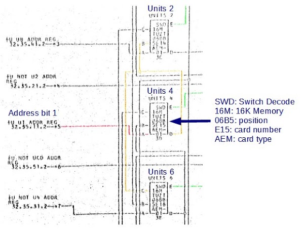
Now we can see the root cause of the problem. The unit address bit 1 (highlighted in red on the ALD) goes into pin A of the Units 4 card and is inverted. The inverted value (pin D, yellow) then goes to the Units 2 and Units 6 cards, generating the decode outputs (green). If something is wrong with this signal, addresses 2, 4, and 6 won't decode, which is exactly the problem encountered. Thus, the Units 4 card seemed like the problem.
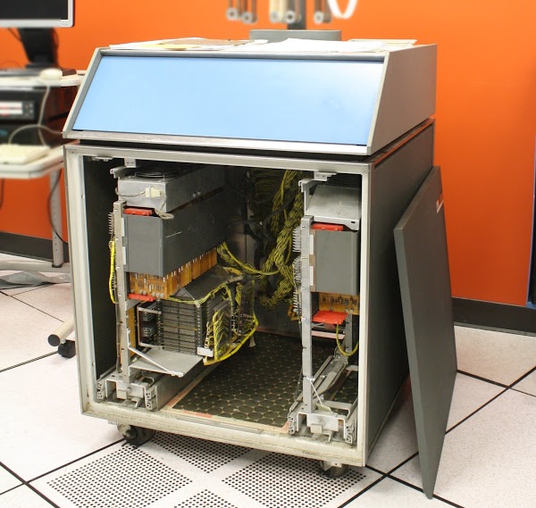
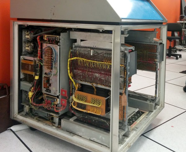
One convenient thing about the IBM 1401 and its peripherals is they are designed for easy maintenance. In many cases, you don't even need any tools. To get inside the IBM 1406, you just pop the front or side panels off (as shown below). The SMS cards have a metal cover to guide the cooling airflow, but that just pops off too. It's easy to attach an oscilloscope to see what's happening, although I didn't need to do that. The SMS cards themselves are easily pulled from their sockets. I'm told you don't even need to power down the system to replace cards, but of course I turned off the power.
I pulled out the card in slot E15, plugged in a replacement card from the 1401 lab's collection, and powered up the system. Much to my surprise, the memory worked perfectly after replacing the card. Some of the engineers (Stan, Marc, and Dave) tested the transistors on the bad card but didn't find any problems. After cleaning the bad card and swapping it back, the memory still worked, so there must have been some dirt or corrosion making a bad connection. They say this is the first problem they've seen due to bad connections, so the thick gold plating on the SMS card contacts must work well.
Conclusion
It's not every day one gets the chance to help fix a 50 year old mainframe, so it was an interesting experience. I was lucky that this problem turned out to be easy to resolve. The guys repairing the tape drives and card reader have much harder problems, since those devices are full of mechanical parts that haven't aged well.Thanks to the members of the 1401 restoration team and the Computer History Museum for their assistance. Special thanks to Stan Paddock, Marc Verdiell and Dave Lion for inviting me to investigate this problem.
The IBM 1401 is demonstrated at the Computer History Museum on Wednesdays and Saturdays (unless there is a hardware problem) so check it out if you're in Silicon Valley (schedule).
Notes and references
[1] The 1406 expansion unit was 29" wide, 30 5/8" deep and 39 5/8" high and weighed 350 lbs. The 10 foot cables between the 1401 computer and the 1406 storage unit are each 1 1/4" thick; one provides power and the other has signals. The 1406 generates 250 watts of heat, which is less than I would have expected. Details are in the installation manual.[2] The three-digit address has six zone bits in total. Four are used as part of the address. The other two zone bits to indicate an indexed address using one of three index registers (which are actually part of core, not separate registers). Indexed addressing was part of the "Advanced Programming" option which cost an extra $105 per month.
[3] For full information on converting addresses to characters, see the IBM 1401 Pocket Reference Manual, page 3.
[4] Scans of the Instructional Logic Diagrams (ILDs) are available online. The memory decode circuits are on page 56. Scans of the Automated Logic Diagrams (ALDs) are also available online; the core memory is in section 42.
[5] The IBM 1401 predates standardized logic symbols, so the logic diagram symbols may be confusing: the triangular symbol is an AND gate. The SWD (Switch Decode) card inverts its inputs, but that isn't shown on the logic diagram.
There are few subtleties in the decoding logic. You might think that the circuit described would decode a 0 digit as a 2 digit since the 1, 4, and 8 bits are clear. However, the IBM 1401 stores the digit 0 as the value 10 (8 bit and 2 bit set), since a blank is stored with all bits clear.
For the decoding using the parity bit, note that the IBM 1401 uses odd parity. For instance, the digit 4 (binary 0100) already has odd parity, so the CD (check digit) parity bit is clear. The digit 5 (binary 0101) has the CD parity bit set so three bits are set in total.
[6] The original idea of SMS cards was to build computers from a small set of standardized cards, but as you can guess from the complexity of the AEM card, engineers created highly-specialized SMS cards for specific purposes. IBM ended up with thousands of different SMS card types, defeating the advantages of standardization. I've created an SMS card database that describes a thousand different SMS cards.
[7] The 06B5 designation indicates which gate holds the card. (Each rack of cards is called a "gate" in IBM terminology. Confusingly, this has nothing to do with a logic gate.) The 06 indicates the 1406 frame. The B indicates a lower frame. Position 5 is in the back right. The same numbering system is used in the IBM 1401 itself. The 1401 is built around the same frame structure as the 1406, except with four frames, stacked 2x2. The left frames are numbered 01, and the right frames are 02. The frames on top are A, and the frames on the bottom are B. Gates 1 through 4 are in the front, and 5 through 8 continue around the back. A typical 1401 gate identifier is "01B2", which indicates the rack on the front of the 1401 below the console. (The use of frames to build computers and peripherals led to the term "main frame" to describe the processing unit itself.)
20 comments:
This is an excellent blog post - with lots of pictures, a clear
description of the bug, the logic behind tracking it down and the
solution.
Nice!!!
I though this was a brilliant debug. Stan, our experimentalist extraordinaire, had helped considerably by testing the machine over several days and narrowing the fault to this 4k block of memory and noticing the particular address pattern. I was already busy at the back re-reading the address decoding section of your previous core memory blog post... We all said "we wish Ken was here" as we walked towards the machine room, ready for an arduous session of deciphering the "nearly incomprehensible" ALDs. And there you were! You found the faulty card in maybe 10 minutes, using only the power of logic. Usually we use the power of the oscilloscope, the power of trial and error, and the power of arguing around a cup of coffee a lot more. Your in-depth knowledge and detailed reverse engineering of the core memory system paid of big time. It's an asset to have you around!
Marc
If you have the time, check this video. The opening melody is played by an IBM 1401.
http://youtu.be/tBw_wSoVQrY
Aside from contact corrosion I would consider checking those 50 year old electrolytic capacitors.
mind-boggling stuff!
The very first machine I ever programmed. An absolute joy. The amount of work this machine could do in just a couple of K (mine had 8) was astonishing, and no matter how tightly you packed your code in, there was always a way to fit more in.
My English is too weak to express the storm of emotions. The article is excellent, of course. And those old computers are simply marvelous!
My 1-st experience was a Soviet Mir-2 decimal-calculation computer. The Assembler was Cyrillic and the 1-st command defined the number of decimal digits in calculations. Transistors as active elements too...
I found this thrilling. Seriously. What a great story you've shared and I am in awe of your skills in this arena.
Also the first machine I ever programmed! As a high school junior in 1972.
I still have card decks for some of the FORTRAN IV assignments, and even have a sheet of "coding paper" that let you fill in formatted card data before sitting down at a card-punch.
I'm still programming today, 43 years later, mainly in C/C++ and Python.
Most Fun Ever. And Hour of Code let's me help pass the joy on to yet another generation.
Thanks so much for your blog... I found it googling Images... I was given a 1401 core memory 30+ years ago, but the donor didn't know what it came from. I have exhibited it at tech fairs, asked every expert I know... and finally today discovered it's identity courtesy of your blog. Thanks!
Thank You--what a fun trip back to "the day".
I've been an ITer for 30 years, but never got
my hands on anything this old-skool-cool.
I've often thought I was born too late...or
too early! Much appreciated.
I went to work for IBM in 1967 which was too late to be trained and work on the 1401. I did uninstall a few. I spent lots of time on System 360 and System 370 and associated hardware. Do you need any 108 driver transistors for those tape drives? I have a few if I can find them.
Bill
Hi Bill! The 1401 team is always happy to have more spare parts if you have 108 transistors lying around. There's contact information at http://ibm-1401.info/ if you want to email or call them.
Sounds like a normal day back in the early 60s. The fun part was running your finger down the diodes to find the hot one.
I spent a few years on shipboard tending Univac 1206 and related Collins Radio gear in the late 60's. Similar resistor transistor logic cards, a few thousand 30 bit words of core memory, and 1/2 inch magnetic tape for external storage. In 3 years we experienced one failure, a logic gate in the ALU. The machines were water cooled, massive things, the logic and memory mounted in heavy shelves that took two men to remove. The front panel display consisted of tiny combination lamp/pushbuttons that glowed orange, I think they were neon. The Naval Tactical Data System. My special charge was maintaining Collins data transmission switches which converted those 30 bit words into a set of 8 phase shifted analog frequencies, which could be superimposed on an AM radio signal for ship to ship communication. More Collins radio gear did the sending and receiving. Later we had some Univac 1218's with actual MSI chips.
Thank you so much for this marvelous article! Love the high resolution pics, detailed (but engaging) technical explanations and detailed reference link to the card info. This could be a great reference item for future restorers. Bravo! Steve Lafferty
Nice read. Brought me back to my days as a IBM Customer Engineer in 1960s London. I looked after a 1401 in-house at the IBM data centre and another for Export Credit, who did all their work on a 8k machine. On one memorable occasion, on closing the back gate of the 1402 card reader, the gate shorted the main power cables where the insulation had decayed. This blew the gate off and sent me crashing across the room to be stopped by the glass on the 14th Flr. window. Memories!
I am a 22 year old physics student with a (still technically undeclared) minor in computer science, and I find this whole concept fascinating. Not just this specific blog post, but the whole idea of not only preserving the history of computing, but also actually running the machines. I have always liked the idea of running obsolete tech. I mean, it may be out of date, and sure, modern machines can do it orders of magnitude faster, but the old stuff still works.
I sometimes save my lab reports and excel spreadsheets on floppy disks. (although I usually keep a backup copy on something that is a bit more stable) You wouldn't believe the look I got from the TA when I plugged a usb floppy drive into my laptop and stuck a disk into it...
Im glad that this kind of stuff is being preserved.
I first heard about the IBM 1401 in High School in my junior year of high school. Another student came into the room and said he had just jammed up a punch card sorter. I asked him where it was and went looking for it. It was in a classroom that had no windows. I signed up for the class for my senior year. The first day I sat right in front of the teacher because I didn't want to miss anything he said. The room was split in half with desks on one side and the 1401 on the other. I was totally hooked. I asked so many questions that the teacher had me gave me the book on how to program it long before the others. I programmed it using SPL. This was in 1973. The school board had upgraded to the IBM 360 and gave the 1401 to my High School. I spent many days after school trying different programs. Often the teacher took me home because I had missed the bus. We didn't have any tape drives but, we had 2 1311 disk drives and 12k of memory. I'm still programming 49 years later. Good Ttimes.
This blog post is a fascinating dive into the complexities of restoring vintage technology! Your detailed explanation and passion for the IBM 1401 mainframe truly bring this piece of computing history to life. Thank you for sharing your expertise!
Post a Comment