The motivation behind BCD is to make working with decimal numbers easier. Programs usually need to input and output numbers in decimal, so if the number is stored in binary it must be converted to decimal for output. Since early microprocessors didn't have division instructions, converting a number from binary to decimal is moderately complex and slow. On the other hand, if a number is stored in BCD, outputting decimal digits is trivial. (Nowadays, the DAA operation is hardly ever used).
One problem with BCD is the 8085's ALU operates on binary numbers, not BCD. To support BCD operations, the 8085 provides a DAA (decimal adjust accumulator) operation that adjusts the result of an addition to correct any overflowing BCD values. For instance, adding 5 + 6 = binary 0000 1011 (hex 0x0b). The value needs to be corrected by adding 6 to yield hex 0x11. Adding 9 + 9 = binary 0001 0010 (hex 0x12) which is a valid BCD number, but the wrong one. Again, adding 6 fixes the value. In general, if the result is ≥ 10 or has a carry, it needs to be decimal adjusted by adding 6. Likewise, the upper 4 BCD bits get corrected by adding 0x60 as necessary. The DAA operation performs this adjustment by adding the appropriate value. (Note that the correction value 6 is the difference between a binary carry at 16 and a decimal carry at 10.)
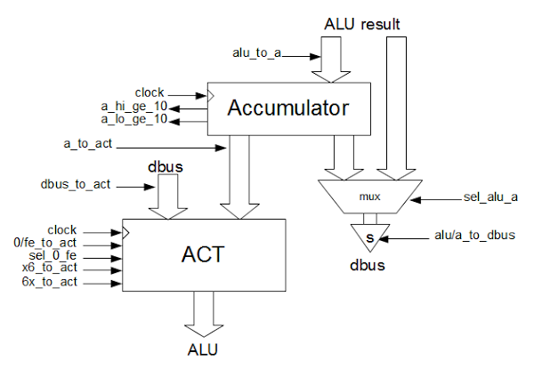
The DAA operation in the 8085 is implemented by several components: a signal if the lower bits of the accumulator are ≥ 10, a signal if the upper bits are ≥ 10 (including any half carry from the lower bits), and circuits to load the ACT register with the proper correction constant 0x00, 0x06, 0x60, or 0x66. The DAA operation then simply uses the ALU to add the proper correction constant.
The block diagram below shows the relevant parts of the 8085: the ALU, the ACT (accumulator temp) register, the connection to the data bus (dbus), and the various control lines.
The circuit below implements this logic. If the low-order 4 bits of the ALU are 10 or more, alu_lo_ge_10 is set. The logic to compute this is fairly simple: the 8's place must be set, and either the 4's or 2's. If DAA is active, the low-order bits must be adjusted by 6 if either the low-order bits are ≥ 10 or there was a half-carry (A flag).
Similarly,
The circuits to load the correction value into ACT are controlled by the
This information is based on the 8085 reverse-engineering done by the visual 6502 team. This team dissolves chips in acid to remove the packaging and then takes many close-up photographs of the die inside.
Pavel Zima converted these photographs into mask layer images, generated a transistor net from the layers, and wrote a transistor-level 8085 simulator.
alu_hi_ge_10 if there's an overflow from the low-order bits. A decimal adjust is performed by loading 6 into the high-order bits of the ACT register and adding it. A carry out also triggers this decimal adjust.
load_act_x6 signal for the low digit and load_act_6x for the high digit. These circuits are shown in my earlier article Reverse-engineering the 8085's ALU and its hidden registers.
Comparison to the 6502
By reverse-engineering the 8085, we see how the simple decimal adjust circuit in the 8085 works.
In comparison, the 6502 handles BCD in a much more efficient but complex way. The 6502 has a decimal mode flag that causes addition and subtraction to automatically do decimal correction, rather than using a separate instruction. This patented technique avoids the performance penalty of using a separate DAA instruction. To correct the result of a subtraction, the 6502 needs to subtract 6 (or equivalently add 10). The 6502 uses a fast adder circuit that does the necessary correction factor addition or subtraction without using the ALU. Finally, the 6502 determines if correction is needed before the original addition/subtraction completes, rather than examining the result of the addition/subtraction, providing an additional speedup.


First of all, really great stuff! I'm currently trying to rebuild the 8085 using TTL chips, and have found your blogs incredibly useful. But I thought I might point out a minor error in your circuit diagram. You say this...
ReplyDelete"If DAA is active, the low-order bits must be adjusted by 6 if either the low-order bits are ≥ 10 or there was a half-carry (A flag)."
but I noticed in the diagram, a_flag and alu_lo_ge_10 are ANDed, meaning that DAA will equal load_act_x6 unless both a_flag and alu_lo_ge_10 are active. Shouldn't they be ORed instead? Any input in greatly appreciated!
Best,
Hannah
Corrections..
ReplyDeleteNORed instead?*
DAA will equal NOT load_act_x6*