Reverse-engineering the 8085's decimal adjust circuitry

In this post I reverse-engineer and describe the simple decimal adjust circuit in the 8085 microprocessor. Binary-coded decimal arithmetic was an important performance feature on early microprocessors. The idea behind BCD is to store two 4-bit decimal numbers in a byte. For instance, the number 42 is represented in BCD as 0100 0010 (0x42) instead of binary 00101010 (0x2a). This continues my reverse engineering series on the 8085's ALU, flag logic, undocumented flags, register file, and instruction set.

The motivation behind BCD is to make working with decimal numbers easier. Programs usually need to input and output numbers in decimal, so if the number is stored in binary it must be converted to decimal for output. Since early microprocessors didn't have division instructions, converting a number from binary to decimal is moderately complex and slow. On the other hand, if a number is stored in BCD, outputting decimal digits is trivial. (Nowadays, the DAA operation is hardly ever used).

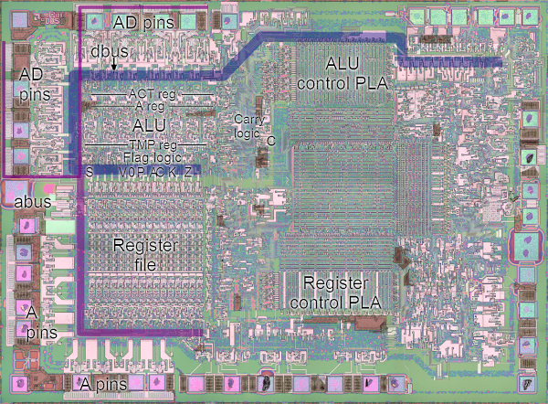
Photograph of the 8085 chip showing the location of the ALU, flags, and registers.

One problem with BCD is the 8085's ALU operates on binary numbers, not BCD. To support BCD operations, the 8085 provides a DAA (decimal adjust accumulator) operation that adjusts the result of an addition to correct any overflowing BCD values. For instance, adding 5 + 6 = binary 0000 1011 (hex 0x0b). The value needs to be corrected by adding 6 to yield hex 0x11. Adding 9 + 9 = binary 0001 0010 (hex 0x12) which is a valid BCD number, but the wrong one. Again, adding 6 fixes the value. In general, if the result is ≥ 10 or has a carry, it needs to be decimal adjusted by adding 6. Likewise, the upper 4 BCD bits get corrected by adding 0x60 as necessary. The DAA operation performs this adjustment by adding the appropriate value. (Note that the correction value 6 is the difference between a binary carry at 16 and a decimal carry at 10.)

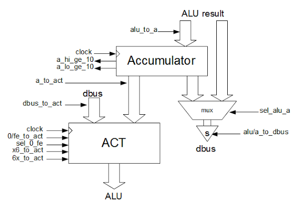
The DAA operation in the 8085 is implemented by several components: a signal if the lower bits of the accumulator are ≥ 10, a signal if the upper bits are ≥ 10 (including any half carry from the lower bits), and circuits to load the ACT register with the proper correction constant 0x00, 0x06, 0x60, or 0x66. The DAA operation then simply uses the ALU to add the proper correction constant.

The block diagram below shows the relevant parts of the 8085: the ALU, the ACT (accumulator temp) register, the connection to the data bus (dbus), and the various control lines.

The accumulator and ACT (Accumulator Temporary) registers and their control lines in the 8085 microprocessor.

The circuit below implements this logic. If the low-order 4 bits of the ALU are 10 or more, alu_lo_ge_10 is set. The logic to compute this is fairly simple: the 8's place must be set, and either the 4's or 2's. If DAA is active, the low-order bits must be adjusted by 6 if either the low-order bits are ≥ 10 or there was a half-carry (A flag).

Similarly, alu_hi_ge_10 is set if the high-order 4 bits are 10 or more. However, a base-10 overflow from the low order bits will add 1 to the high-order value so a value of 9 will also set alu_hi_ge_10 if there's an overflow from the low-order bits. A decimal adjust is performed by loading 6 into the high-order bits of the ACT register and adding it. A carry out also triggers this decimal adjust.

Schematic of the decimal adjust circuitry in the 8085 microprocessor.

Schematic of the decimal adjust circuitry in the 8085 microprocessor.

The circuits to load the correction value into ACT are controlled by the load_act_x6 signal for the low digit and load_act_6x for the high digit. These circuits are shown in my earlier article Reverse-engineering the 8085's ALU and its hidden registers.

Comparison to the 6502

By reverse-engineering the 8085, we see how the simple decimal adjust circuit in the 8085 works. In comparison, the 6502 handles BCD in a much more efficient but complex way. The 6502 has a decimal mode flag that causes addition and subtraction to automatically do decimal correction, rather than using a separate instruction. This patented technique avoids the performance penalty of using a separate DAA instruction. To correct the result of a subtraction, the 6502 needs to subtract 6 (or equivalently add 10). The 6502 uses a fast adder circuit that does the necessary correction factor addition or subtraction without using the ALU. Finally, the 6502 determines if correction is needed before the original addition/subtraction completes, rather than examining the result of the addition/subtraction, providing an additional speedup.
This information is based on the 8085 reverse-engineering done by the visual 6502 team. This team dissolves chips in acid to remove the packaging and then takes many close-up photographs of the die inside. Pavel Zima converted these photographs into mask layer images, generated a transistor net from the layers, and wrote a transistor-level 8085 simulator.

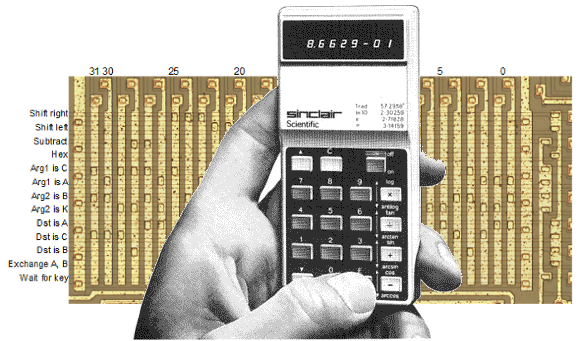
Reverse-engineering and simulating Sinclair's amazing 1974 calculator with half the ROM of the HP-35

I've reverse-engineered the Sinclair Scientific calculator. The remarkable thing about this calculator is they took a simple 4-function calculator chip and reprogrammed its 320-instruction ROM to be a full scientific calculator. By looking at the chip, I've extracted the original code, reverse-engineered how it works, and written a JavaScript simulator that runs the original code and shows what the calculator is doing internally.

The simulator is at righto.com/sinclair. My earlier TI calculator simulator is at righto.com/ti. (The image above is courtesy of Hackaday.)

I wouldn't have given a nickel for their stock: Visiting Apple in 1976

A guest posting from William Fine:

I saw the "Jobs" movie yesterday and it revived some ancient memories of my dealings with Jobs and Holt in the "old days"! When I returned home, I researched Rod Holt on the Internet and ran across your Power Supply Blog, which I found most interesting. Perhaps you can add my ensuing comments to your blog as you see fit.

In 1973 I started a company in my garage in Cupertino to design and manufacture custom Magnetic Products. It was called Mini-Magnetics Co. Inc. After a few months I was forced out of the garage into a small office complex on Sunnyvale-Saratoga Road, and had about 5/10 employees.

I believe it was around 1975/76 or so, I had a visit from a insulation and wire salesman named Mike Felix. He informed me that I may soon be getting a call from a new /start-up company called Apple Computer located just a few blocks away in Cupertino. He gave them my name when he was asked to recommend a Magnetics manufacturing house.

I promptly forgot about it, as I was already quite busy and I never had to solicit business or even advertise. A week or two went by, and I received a call from a female at Apple who set up a appointment for the next day with a guy named Steve Jobs. She gave me the address and it turned out to be located in a office complex located just behind the "Good Earth" restaurant.

The next day I went over to the location and knocked on the door, and it was opened by Jobs, with Wozniack in the background and a young hippie looking girl at a desk in the corner talking on the phone while eating. That was Apple Computer. They had just moved out of their garage into this new location. It appeared to be a large room with "stuff" scattered hap-hazardly all over, on benches and on the floor. From Jobs' appearance, I was a bit afraid to even shake hands with him, especially after getting a whiff of his body odor!

He immediately took me over to a bench that had a few cardboard boxes on it and showed me some transformer cores, bobbins and spools of wire, and unfolded a hand written diagram of the various magnetic components that he wanted me to wind and assemble for Apple.I took a quick look, and while it was all quite sketchy, looked do-able. He said that he needed them within 10 days and I said ok, since he was furnishing the materials.

I told him that I would call him with a quote after I got back to my office and he said ok and as we were parting he mentioned that if I had any technical questions to get a hold of a guy named Rod Holt and wrote down a phone number where he could be reached.

As I recall, there were about 5-6 magnetic components from simple toroids to a complex switching main power transformer. I believe that the price came to about $10.00 per set,and they wanted 35 sets, so the entire matter would be about $350.00. I called it into Apple the next day and they gave me a Purchase Order number over the phone. When I asked if they would be mailing me a hard copy confirming the order, they had no idea of what I was talking about!

I figured, what the hell, worst case, I would be out $350 bucks if they didn't pay the bill. No big deal.

After I got into examining the sketches I discovered something quite interesting about the power transformer. In all previous designs that I had seen, there was a primary, a base feedback winding and several output windings. What Holt had contrived was a interesting method of assuring excellent coupling of the base winding by using a single strand of wire from a multi-filar bundle that was custom ordered from the wire factory. For example, I think that there was a bundle of 30 strands twisted together, which were all coated in red insulation and one strand of green insulation also twisted together in the bundle, which gave a precise turns ratio together with excellent coupling between the windings.

I am uncertain if that contributed much to improving the efficiency of the switcher, but it seemed clever at the time I discovered it. That transformer, is the one that is shown with the copper foil external shield pictured in your blog. I did speak with Holt once or twice but never met him in person.

The 35 sets of parts were delivered on time and much to my surprise, we were paid within 10 days. I attributed that to the arrival of Mike Markkula onto the scene who had provided some money and organization to Apple.

At the time, after seeing the Apple operation, I wouldn't have given a nickle for a share of their stock if it had been offered! Ha!

I had been involved with power supplies for many years prior to this Apple issue, and can say that switchers were known for a long time, but only became practical with the advent of low loss ferrite core materials and faster transistors as your blog implies.

So, thats the Apple Power Supply story ! Be happy to answer any questions that you may come up with. Regards, wpf

Simulating a TI calculator with crazy 11-bit opcodes

I've built a register-level simulator of a 1974 TI calculator chip that shows what actually happens inside a calculator when you perform operations and shows the calculator source code as it executes. The architecture of the calculator chip is pretty interesting, with 11-bit opcodes, a 9-bit address bus, and 44-bit BCD registers. The chip doesn't support multiplication or division, so these are performed with repeated addition or subtraction.

The simulator is at righto.com/ti.