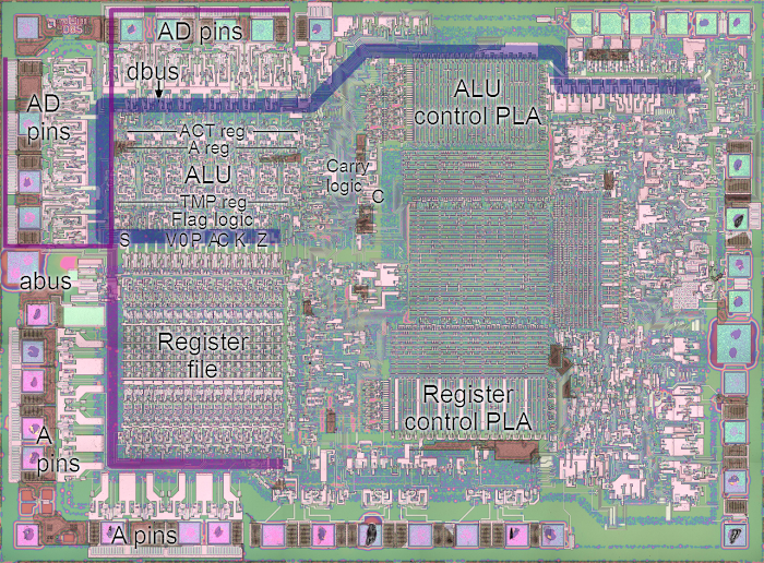
The arithmetic-logic unit is a key part of the microprocessor, performing operations and comparisons on data. In the 8085, the ALU is also a key part of the data path for moving data. The ALU and associated registers take up a fairly large part of the chip, the upper left of the photomicrograph image below. The control circuitry for the ALU is in the top center of the image. The data bus (dbus) is indicated in blue.
The real architecture of the 8085 ALU
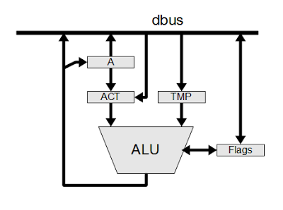
The following architecture diagram shows how the ALU interacts with the rest of the 8085 at the block-diagram level. The data bus (dbus) conneccts the ALU and associated registers with the rest of the 8085 microprocessor. There are also numerous control lines, which are not shown.The ALU uses two temporary registers that are not directly visible to the programmer. The Accumulator Temporary register (ACT) holds the accumulator value while an ALU operation is performed. This allows the accumulator to be updated with the new value without causing a race condition. The second temporary register (TMP) holds the other argument for the ALU operation. The TMP register typically holds a value from memory or another register.
The 8085 datasheet has an architecture diagram that is simplified and not quite correct. In particular, the ACT register is omitted and a data path from the data bus to the accumulator is shown, even though that path doesn't exist.
The accumulator and ACT registers
To the programmer, the accumulator is the key register for arithmetic operations. Reverse-engineering, however, shows the accumulator is not connected directly to the ALU, but works closely with the ACT (accumulator temporary) register.The ACT register has several important functions. First, it holds the input to the ALU. This allows the results from the ALU to be written back to the accumulator without disturbing the input, which would cause instability. Second, the ACT can hold constant values (e.g. for incrementing or decrementing, or decimal adjustment) without affecting the accumulator. Finally, the ACT allows ALU operations that don't use the accumulator.
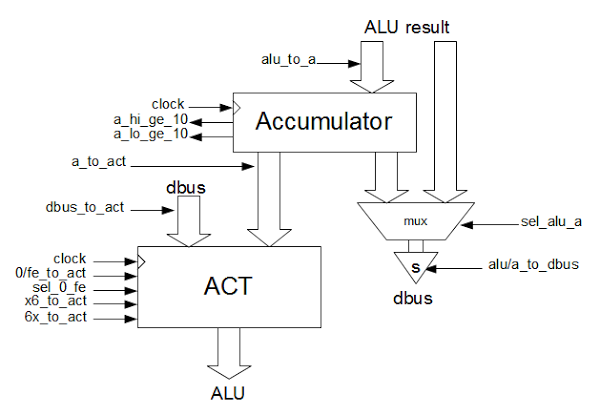
The diagram above shows how the accumulator and ACT registers are connected, and the control lines that affect them. One surprise is that the only way to put a value into the accumulator is through the ALU. This is controlled by the alu_to_a control line. You might expect that if you load a value into the accumulator, it would go directly from the data bus to the accumulator. Instead, the value is OR'd with 0 in the ALU and the result is stored in the accumulator.
The accumulator has two status outputs: a_hi_ge_10, if the four high-order bits are ≥ 10, and a_lo_ge_10, if the four low-order bits are ≥ 10. These outputs are used for decimal arithmetic, and will be explained in another article.
The accumulator value or the ALU result can be written to the databus through the sel_alu_a control (which selects between the ALU result and the accumulator), and the alu/a_to_dbus control line, which enables the superbuffer to write the value to the data bus. (Because the data bus is large and connects many parts of the chip, it requires high-current signals to overcome its capacitance. A "superbuffer" provides this high-current output.)
The ACT register can hold a variety of different values. In a typical arithmetic operation, the accumulator value is loaded into the ACT via the a_to_act control. The ACT can also load a value from the data bus via dbus_to_act. This is used for the ARHL/DAD/DSUB/LDHI/LDSI/RDEL instructions (all of which are undocumented except DAD). These instructions perform arithmetic operations without involving the accumulator, so they require a path into the ALU that bypasses the accumulator.
The control lines allow the ACT register to be loaded with a variety of constants. The 0/fe_to_act control line loads either 0 or 0xfe into the ACT; the value is selected by the sel_0_fe control line. The value 0 has a variety of uses. ORing a value with 0 allows the value to pass through the ALU unchanged. If the carry is set, ADDing to 0 performs an increment. The value 0xfe (signed -2) is used only for the DCR (decrement by 1) instruction. You might think the value 0xff (signed -1) would be more appropriate, but if the carry is set, ADDing 0xfe decrements by 1. I think the motivation is so both increments and decrements have the carry set, and thus can use the same logic to control the carry.
Since the 8085 has a 16-bit increment/decrement circuit, you might wonder why the ALU is also used for increment/decrement. The main reason is that using the ALU allows the condition flags to be set by INR and DCR. In contrast, the 16-bit increment and decrement instructions (INX and DCX) use the incrementer/decrementer, and as a consequence the flags are not updated.
To support BCD, the ACT can be loaded with decimal adjustment values 0x00, 0x06, 0x60, or 0x66.
The top and bottom four bits of ACT are loaded with the value 6 with the 6x_to_act and x6_to_act control lines respectively.
It turns out that the decimal adjustment values are easily visible in the silicon. The following image shows the silicon that implements the ACT register. Each of the large pink structures is one bit. The eight bits are arranged with bit 7 on the left and bit 0 on the right. Note that half of the bits have pink loops at the top, in the pattern 0110 0110. These loops pull the associated bit high, and are used to set the high and/or low four bits to 6 (binary 0110).
Building the 8-bit ALU from single-bit slices
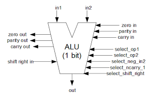
In my previous article on the 8085 ALU I described how each bit of the ALU is implemented. Each bit slice of the ALU takes two inputs and performs a simple operation: or, add, xor and, shift right, complement, or subtract. The ALU has a shift right input and a carry input, and generates a carry output. In addition, each slice of the ALU contributes to the parity and zero calculations. The ALU has five control lines to select the operation.
The ALU has seven basic operations: or, add, xor,
and, shift right, complement, and subtract. The following table shows the five control lines that select the operation, and the meaning of the carry line for the operation. Note that the
meaning of carry in and carry out is different for each operations. For bit operations, the implementation of the ALU circuitry depends on a particular carry in value, even though carry is meaningless for these operations.
| Operation | select_neg_in2 | select_op1 | select_op2 | select_shift_right | select_ncarry_1 | Carry in/out |
|---|---|---|---|---|---|---|
| or | 0 | 0 | 0 | 0 | 1 | 1 |
| add | 0 | 1 | 0 | 0 | 0 | /carry |
| xor | 0 | 1 | 0 | 0 | 1 | 1 |
| and | 0 | 1 | 1 | 0 | 1 | 0 |
| shift right | 0 | 0 | 1 | 1 | 1 | 0 |
| complement | 1 | 0 | 0 | 0 | 1 | 1 |
| subtract | 1 | 1 | 0 | 0 | 0 | borrow |
The eight-bit ALU is formed by linking eight single-bit ALUs as shown below. The high-order bit is on the left, and the low-order bit on the right, matching the layout in silicon. The carry, parity, and zero values propagate through each ALU to form the final values on the left. The right shift input is simply the bit from the right, with the exception of the topmost bit which uses a special shift right input. The auxiliary carry is simply the carry out of bit three. The control lines to select the operation are fed into all eight ALU slices. By combining eight of these ALU slices, the whole 8-bit ALU is created. The values from the top bit are used to control the parity, zero, carry, and sign flags (as well as the undocumented K and V flags). Bit 3 generates the half carry flag.
The control lines
The ALU uses 29 control lines that are generated by a PLA that activates the right control lines based on the opcode and the position in the instruction cycle. For reference, the following table lists the 29 ALU control lines and the instructions that affect them.| Control line | Relevant instructions |
|---|---|
ad_latch_dbus, write_dbus_to_alu_tmp, /ad_dbus |
IN/ |
/ad_dbus |
ARHL/ |
/ |
all |
/dbus_to_act |
ARHL/ |
a_to_act |
ACI/ |
0/fe_to_act |
all |
sel_alu_a |
all |
alu_to_a |
ACI/ |
/ |
DAA |
sel_0_fe |
DCR |
store_v_flag |
ACI/ |
select_shift_right |
ARHL/ |
arith_to_flags |
ACI/ |
bus_to_flags |
POP PSW |
|
DAD/ |
|
ACI/ |
shift_right_in_select |
ARHL |
xor_carry_in |
ANA/ |
select_op2 |
ANA/ |
|
LDHI/ |
/ |
0 except for ACI/ |
select_op1 |
ACI/ |
select_ncarry_1 |
ACI/ |
In combination with first control line, write_dbus_to_alu_tmp |
ADC/ |
select_neg_in2 |
CMA/ |
carry_to_k_flag |
DCX/ |
store_carry_flag |
ACI/ |
xor_carry_result |
xor for ANA/ |
/latch_carry use_carry_flag |
CMC/LDHI/LDSI |
Conclusions
By reverse-engineering the 8085, we can see how the ALU actually works at the gate and silicon level. The ALU uses many standard techniques, but there are also some surprises and tricks. There are two registers (ACT and TMP) that are invisible to the programmer. You'd expect a direct path from the data bus to the accumulator, but instead the data passes through the ALU. The increment/decrement logic uses the unexpected constant 0xfe, and there are two totally different ways of performing increment/decrement. Several undocumented instructions perform ALU operations without involving the accumulator at all.This information builds on the 8085 reverse-engineering done by the visual 6502 team. This team dissolves chips in acid to remove the packaging and then takes many close-up photographs of the die inside. Pavel Zima converted these photographs into mask layer images, generated a transistor net from the layers, and wrote a transistor-level 8085 simulator.


沙发
ReplyDeleteVery interesting, I guess the 8086 has a very similar datapath since it takes 3 cycles for register-register ALU operations. At the time it looks like Intel were more concerned about reducing chip area than making things fast, hence single ALU, single-ported register file, big common databus, etc.
ReplyDeleteHeck, you guys are smart.
ReplyDelete