What you get
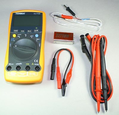
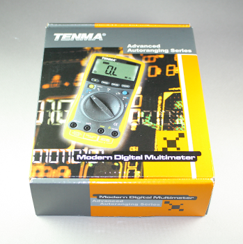
The DMM comes with a temperature probe, battery, alligator clips, and test probes. Note that the test probes have very short metal tips, unlike the long tips on most probes. The alligator clip probes are a nice addition. My biggest complaint with the DMM is the temperature probes connections are soldered with no strain relief so I worry the wires will break off.
The DMM also comes with a pocket-sized 36 page operating manual - a real, physical manual on paper, not a PDF file like most products these days. The DMM doesn't really need a manual - functions work pretty much as you'd expect - but it's nice to have the manual.
Specifications
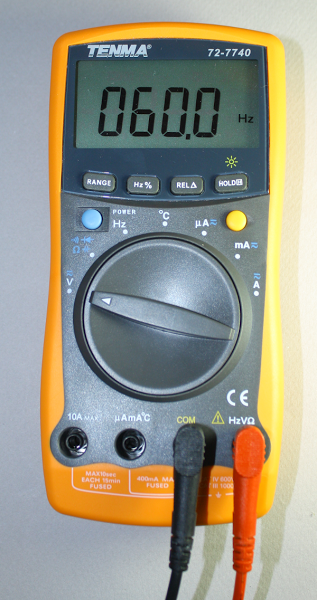
The DMM is autoranging with maximum reading of 3999. It is full-size (177mm × 85mm × 40mm), not a pocket DMM, and has a built-in stand. The LCD display is large and clear and has a backlight, which is nice if I ever end up using the meter in the dark. It has 10MΩ input impedance and maximum voltages of 1000V DC and 750V AC. The top current range is 10A.The DMM also includes capacitance, diode, temperature, frequency, and duty cycle measurements. The top capacitance range (100µF) can take up to 15 seconds to get a measurement, so be patient with those big electrolytics. The lowest capacitance range is 40 nF with 10pF resolution claimed. The DMM also has a continuity buzzer, although I find the sound crackles a bit. The temperature readings are only in °C; I know using Fahrenheit makes me a bad person, but that's what I need to check my appliances. The temperature range is -40°C to 1000°C. The upper range is hotter than I need, but since I sometimes go outside below -40°C my multimeter should be able to handle it too.
Buttons provide hold and relative mode. The meter goes into sleep mode after 30 minutes.
I don't have the equipment to measure the accuracy of the DMM myself, so I'm going off the published values. The specification for DC voltage accuracy is a reasonable ±0.8%; the considerably more expensive Fluke 177 has ±0.09% accuracy, so you get what you pay for.
The function knob has 7 positions: V, resistance/capacitance/diode/continuity, Hertz, °C, µA, mA, and A. The blue function button switches between AC and DC or switches among resistance, capacitance, diode, and continuity.
There are a few functions found in more advanced multimeters that aren't found here: min/max measurement, RS-232 support, °F, a 4nF capacitance scale, and an analog bar graph.
For full specifications, see the specification chart.
Teardown
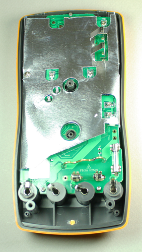
Of course I was interested in what was inside the multimeter and opened it up. The instruction manual describes how to remove the screws under the feet. The force required to pry the case apart made me a little nervous, but it snapped open without breaking anything. Note that the case must also be opened in this way to replace the fuses - they are not accessible from the battery compartment. Unfortunately I tend to blow fuses a lot measuring charger performance, but this may motivate me to be more careful.A foil shield covers most of the circuit board, with holes for some adjustments. Near the bottom is a thick wavy wire, which is the precision resistor used for the high-current measurements, a fraction of an ohm. There's nothing particularly interesting directly under the foil shield; almost all the components are on the other side.
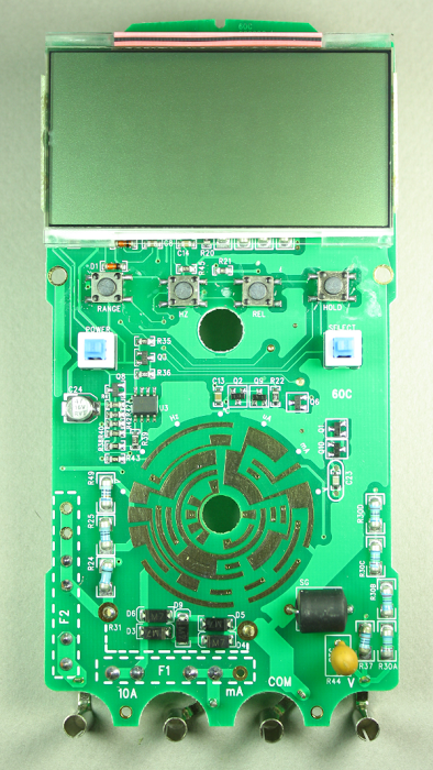
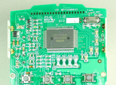
Removing the circuit board and flipping it over shows the circuitry. The large LCD display is at the top, with the pushbuttons below. The most visually striking part of the board is the round circuitry for the function knob, which I will explain in more detail below. To the left are three precision (blue) resistors for mA and µA measurement. Below are 5 diodes which I believe are for input protection. The large black cylinder in the lower right appears to be a spark gap to protect the input from high voltages - the DMM is rated to 1000V DC overload protection. Below it is a large yellow PTC resistor to protect from input overloads. The 8-pin IC is a STMicroelectronics TL062C low power J-FET dual op amp.
How the function selector switch works
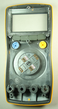
Rotary switches have always been mysterious to me. The pattern on the circuit board seems to be made up of random lines rather than any obvious switch contacts, and looks as much like an Aztec symbol as a switch. So I figured it was time to dive in and figure out how it works.The selector knob has 7 positions, rotating a bit under 180 degrees in total. Looking at the back of the selector knob, you can see six independent sliders for six separate switching circuits. Each slider has two peaks in the middle, which bridge two contacts on the circuit board. Note that the two outermost sliders are offset 90 degrees from the others. Since the knob turns a bit under 180°, the sliders n
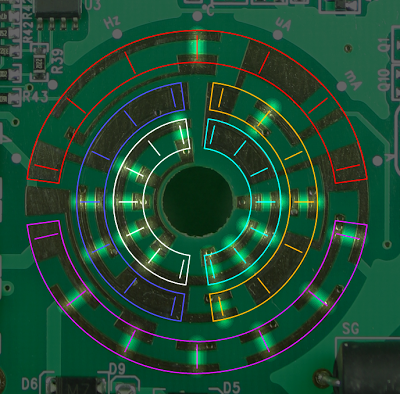
The following diagram shows how the switches work. Each of the six colored semi-circular rings is associated with one of the sliders. The seven lines inside each semicircle indicate the seven possible positions of the associated slider. The most counterclockwise position in each ring is the V setting, followed by Ω, Hz, °C, µA, mA, and A. If there are two traces lined up with the slider, the slider will connect the two traces.
One surprise is that many of the traces don't actually form a circuit. The highlighted positions in the diagram are active positions that close two contacts, but the other positions don't form a connection. In particular, the red ring is only active in one position, and the blue ring in two positions. Many positions have the same circuit trace on both ends of the line, which means the switch does nothing and the trace is unnecessary. My guess is that the redundant metal is there because metal-on-metal is lower friction than metal-on-circuit-board.
The white, cyan, and blue rings ground various combinations of "mode" pins on the IC to select the function. The left half of the purple ring directs the µAmA°C input to the appropriate circuit based on the function. The right half of the purple ring directs the HzVΩ input appropriately. The red ring has a connection only for the °C setting. The orange ring makes connections for Ω, °C, and A.
Conclusion
The 72-7740 DMM is a solid meter that gets the job done and I have only minor complaints. It currently sells for about $70. Inexplicably, the next model up, the 7745, is cheaper despite having true RMS and a serial RS-232 output. The model down, the 7735 is a good deal at about half the price; it also has RS-232, although it lacks temperature measurement, the backlight, and sleep mode.
Thanks to Newark element14 for giving me this digital multimeter free for review. (Newark element14 consists of the merger of the well-known Newark electronics distributor and the element14 online electronics community into a single global brand.)
http://www.youtube.com/watch?v=M-FZP1U2dkM
ReplyDeleteThanks, LoveMHZ for the high-voltage multimeter destruction video. It's pretty impressive - I give it a thumbs-up.
ReplyDeleteHi,
ReplyDeleteThis Chinese company are really hard to understand... This multimeter is a re-badged UNI-T UT60C (http://www.uni-trend.com/UT60C.html)
I found your review because I just opened my UNI-T and googled the chip name. The two pcb are almost the same with a few difference in input protection. Here is a (bad) picture: http://www.casimages.com/img.php?i=130603110701831274.jpg
dgedi, interesting that the Tenma and UNI-T multimeters are nearly identical. I wonder why UNI-T replaced the spark gap (lower right) with two smaller ones. (Is there a part number on the spark gap?)
ReplyDeleteHi Ken,
ReplyDeleteHere is 2 more picture if you want to play at "Spot the difference" :
http://www.casimages.com/a/QaHU6
I didn't find information for the green varistor (?)
Overall, I'm happy with the multimeter, it feel robust and accurate. I also like the t° feature. For 50us$ delivered to France from Hong-Kong, it's a bargain imo.
Oh, I forgot, have a look at the top right of the board, there is a jumper to remove in order to have the t° in Fahrenheit!
ReplyDeleteIs that a 250V fuse? I never really understood how a 1000V rated DMM would come with a 250V rated fuses...
ReplyDeleteIce-Tea: yes, it's a 250V fuse. The manual says never to measure a current when the voltage is more than 250V. I'm not sure how this squares with the 1000V rating. This combination of 250V fuse and 1000V rating seems to be common for DMMs, so I'm a bit puzzled.
ReplyDelete