Getting started
The basic idea is you measure a waveform with the oscilloscope and use spectral analysis to see the frequency spectrum of this waveform. The first step is to display the desired input, which I assume you know how to do.Next, to start Spectral analysis, go to Math -> Spectral Setup.... Choose Magnitude, Channel 1, and Ok. This will display the spectrum of channel 1 as the Math1 curve.
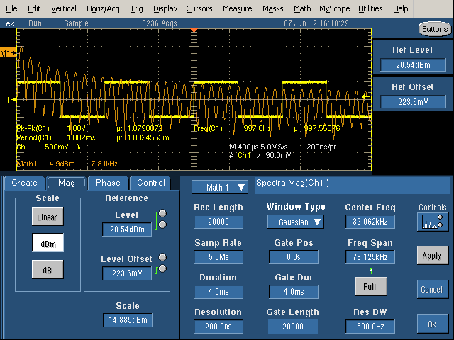
You'll discover there are a dozen settings with complex interactions. There are three columns of controls: Time Controls (Record Length, Sample Rate, Duration, and Resolution), Gating Controls (Gate Position, Gate Duration, and Gate Length), and Frequency Controls (Center Frequency, Frequency Span, and Resolution Bandwidth).
The Time Controls select how much data is collected. Record Length is the number of data points collected, Sample Rate is the sampling frequency, Duration is the time interval collected, and Resolution is the time between samples.
The Gating Controls select which data is actually used for the FFT, since you can use less data than you are collecting. Gate Duration is the sub-region of the Duration that is processed, and Gate Length is the number of samples in the Gate Duration. The Gate Duration is the interval between vertical yellow lines in the display.
The Frequency Controls select what results are displayed. The displayed frequency spectrum is centered on Center Frequency with total width of Frequency Span. Clicking Full will make the Frequency Span as large as possible with the existing settings. The Resolution Bandwidth specifies how detailed the frequency spectrum is, so smaller is "better".
Controlling the parameters
By clicking on a parameter, two of the parameters will be assigned to multi-function knobs, indicated by two circles next to the parameter and a green line indicating which knob controls it. Note that due to interdependencies between the parameters, adjusting one parameter can change other parameter. Also, the range of a parameter may be constrained by other parameters. You can also click on the number and manually entera value, or often set it to the minimum or maximum value, which can be convenient.Advice
First figure out the maximum frequency you're interested in, the time period you're interested in, and the minimum frequency resolution you want.Set the Sample Rate to at least twice the maximum frequency of interest. (Note that Sample Rate is basically in Hertz; s means samples per second, not seconds for Sample Rate. Resolution is the reciprocal of Sample Rate.)
Duration controls the Resolution Bandwidth; a longer Duration yields a smaller (better) Resolution Bandwidth. At least two cycles of the lowest frequency of interest must fit into the Duration. The Duration should include several cycles of the waveform of interest. Note that if the Duration is multiple seconds, it will inconveniently take a long time to collect data before showing you the waveform. And if the Record Length is long, the processing time will be long.
The Record Length will be determined from the Sample Rate and Duration, Generally around 20,000 is a good value. A much smaller value won't give you good frequency resolution, and a much larger value will slow down processing.
The Resolution control is usually the best Time control to adjust, since the others interact with each other in annoying ways.
For the Gating controls, I recommend leaving the Window Type at Gaussian and the Gate Position at 0 unless you know you want to do something else. you probably want the Gate Duration to be as large as the Duration, or else you're wasting data and getting a worse Resolution Bandwidth. If the Gate Duration is smaller than the Duration, it will be displayed as vertical yellow lines that show the part of the waveform that is getting processed.
For the Frequency Controls, you probably want Center Frequency to be half of Frequency Span; this means that you're seeing the full spectrum starting at 0. It's very easy for Center Frequency to get larger, which means you're looking at a random region in the middle of the middle of the spectrum, so you may need to continually set the Center Frequency back to the minimum value. It usually works best to modify freqency by increasing the Frequency Span and decreasing the Center Frequency, to keep the two in sync. If the frequency spectrum looks like sine waves rather than spikes, the Resolution Bandwidth is probably too large.
Be careful you don't clip the input waveform on the top of the screen, as this will mess up the spectrum. Set the vertical scale so it fits.
Example: Square wave frequency spectrum
An easy example is to generate the frequency spectrum of the 1kHz calibration square wave. (Just connect the probe to the calibration output on the oscilloscope.) The theoretical spectrum for a square wave is spikes for the odd harmonics, with height proportional to 1/n. Specifically, a 1 volt peak-to-peak square wave will have harmonics of 2/π/n volts peak-to-peak for odd n, or 0.63V and 0.21V for the first two (odd) harmonics. Converting the harmonics to RMS voltages by dividing by sqrt(2) yields theoretical RMS voltages of 0.450V and 0.150V for the first two harmonics.

The above picture shows a first attempt at generating the frequency spectrum (orange) of the square wave (yellow). The duration is too short - it only includes 4 cycles of the waveform, so the Resolution Bandwidth is large (500Hz). The result is the spikes are spread out into sine-like curves and the spectrum is not very distinct.
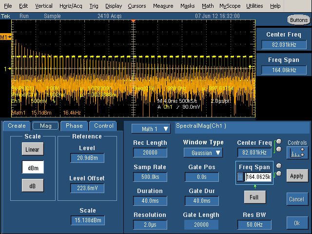
In the above picture, the duration has been increased to 40mS, so 40 cycles of the waveform are included. With a long duration, the Resolution Bandwidth is narrow (50Hz), so the harmonics are narrow spikes as desired. However, with a wide Frequency Span, the harmonics are crammed together and hard to see.
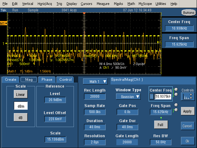
To see the spectrum in more detail (zoomed-in), decrease the Frequency Span, which gives more detail of the spectrum. However, note that the spikes are all almost the same size. since the Center Frequency is not half of the Frequency Span, we're looking at the middle of spectrum (3.125kHz to 18.75kHz), rather than starting at 0Hz. It is very easy to accidentally shift the spectrum range and get confused about what you're seeing, so be cautious.
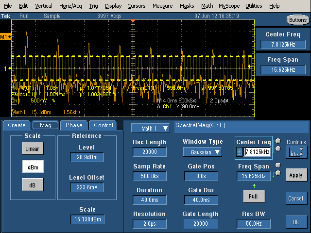
Finally, with the Center Frequency set to half of the Frequency Span, the image above shows the spectrum starting at 0. The frequency scale (Math1) is 1.56kHz per grid line, so the spikes are at 1kHz, 3kHz, 5kHz, etc. as expected. (Inconveniently, I can't find a way to get the frequency scale to be round numbers.)
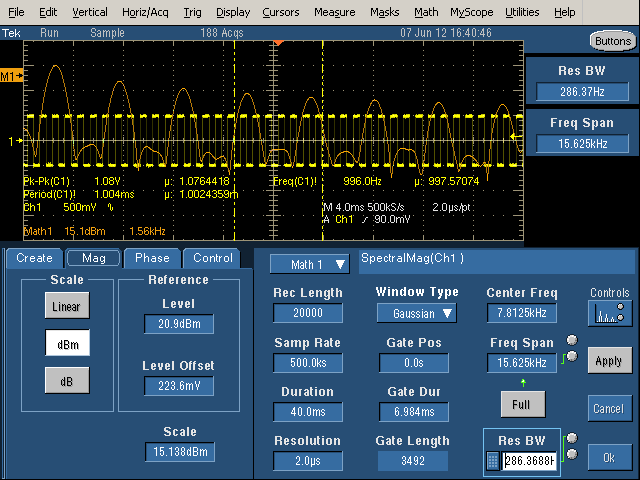
With the Gate Duration decreased, note the vertical yellow lines showing the gate region. Only the signal between the lines is being processed. This increases the Resolution Bandwidth (i.e. makes it worse), so the harmonics are now considerably wider than the spikes seen previously.
The theory behind dB and dBm
The dB and dBm scales are logarithmic, which allows harmonics with a large range of powers to be displayed: when the power increases by a factor of 10, the dB measurement increases by 10 dB. dB is measured against an arbitrary reference power, so the fomula is dB = 10 * log10(power / powerreference). Since the oscilloscope measures voltage, not power, the fomula actually used is dB = 20 * log(V / Voffset), for a fixed offset voltage. Voffset corresponds to 0 dB. Since power is proportional to V^2, increasing the voltage by a factor of 10 increases the power by a factor of 100 which increases the dB value by 20 dB.For the dBm scale, the offset voltage is set to 223.6mV. Although this value may seem random, there is an explanation. The definition of dBm is 10*log(power), where power is the RMS power in milliwatts. dBm is defined with a fixed impedance of 50Ω. (Other fields use different impedances for dBm, for example audio work uses 600Ω.) Working through some math yields Vref = sqrt(50Ω*1mW) = 223.6mV. (See Wikipedia for more explanation of dBm.)
The oscilloscope's dB and dBm settings
On the oscilloscope, the Spectral controls affecting the dB display are Level, Offset, and Scale. Scale is the number of dB per division. Level controls the position of the M1 zero dB position, measured in dB below the top of the screen. Finally, Offset defines what voltage is 0 dB. The default Offset is 223.6 mV as explained above. Increasing Offset shifts the spectrum down with respect to the M1 zero position. For instance, Offset of 707.09 mV shifts the curve down by 10 dB, and 2.236V shifts the curve down 20 dB.The scale values for Math1 are used to display the dBm curve. The vertical scale shows the number of dBm per division, and the horizontal scale shows the frequency per division. The M1 indicator on the left shows the position of 0 dBM. Note that dBm values can be positive or negative.
In the Math controls, the controls are Pos and Scale - Pos is the number of divisions that M1 (0 dBm) is above the center line, so Level = (4 - pos) * Scale.
On the oscilloscope, there are few differences between the dB and dBm settings. dBm defaults to centering the spectrum on the screen (which generally puts M1 high up), and using 223.6mV as the offset. dB defaults to centering M1 on the screen (which generally puts the spectrum lower). If you adjust the Level, Offset, and Scale to be equal, the dBm and dB settings give the same results, so they aren't fundamentally different. The default Level and Scale are usually ugly numbers; you can adjust them to round values.
The square wave spectrum gives an example of dBm in use. Looking at the theoretical values for the square wave, the first harmonic of 0.45V is 20*log(450mV/223.6mV) = 6.1dBm and the second odd harmonic of 0.15V is 20*log(150mV/223.6mV) is -3.5dBm. Looking at the measured harmonics, the first is about 0.4 divisions above the M1 mark, and the second is about 0.2 divisions below the mark. Since the scale is 15.1dBM / division, this yields measured values of 6dBm and -3dBm, close to the theoretical values.
Understanding the linear scale
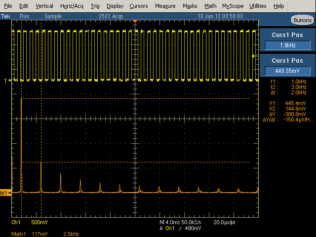
The linear scale displays the RMS voltage of each harmonic. The M1 arrow at the left indicates the 0 position (which can be adjusted). The Math1 Scale shows how many mV per vertical division, and how many kiloHertz per horizontal division. Position shows the number of divisions M1 is above the center line.
Changing the scale to Linear shows how the harmonics in the example drop off rapidly as 1/N: 1, 1/3, 1/5, 1/7, etc. (Note that higher-order harmonics are much harder to see with the linear scale than with the dB scale.) Aligning cursors with the first two harmonics indicate the first harmonic is 1kHz at 445.4mV, and the third harmonic is 3kHz at 144.6mV. These values are close to the theoretical values of 450mV and 150mV. The values can also be determined from the display using the scale. In this example, the Math1 scale is 117mV per vertical division and 2.5kHz per horizontal division. The first harmonic is about 3.8 divisions above the 0 level, which works out to 445mV.
Reading voltage and frequency values can be inconvenient because the scale usually ends up with inconveniently non-round values per division. Using a math cursor, as above, make this easier. The cursors are accessed under Cursors > Cursor Setup, and then moved to the desired positions.
Some relations between the controls
Many of the control values are related to other values by simple equations. The following relationships may help understand the controls.- 1 / Sample Rate = Resolution.
Resolution is just the time between samples. - Record Length = Sample Rate * Duration.
Record Length is the total number of samples collected. - Gate Length = Gate Duration * Sample Rate.
Gate Length is the total number of samples processed. - Gate Duration ≤ Duration.
The Gate Duration must be smaller than the total Duration. - Gate Length ≤ Record Length.
The Gate Length must be smaller than the total Length. - Center Frequency ≥ Frequency Span / 2.
The minimum frequency in the range must be positive. - Resolution Bandwidth = 2 / Gate Duration.
The slowest waveform must fit into the duration at least twice. - Freq Span ≤ Sample Rate / 2.
The Nyquist limit requires at least two samples at the highest frequency. - Spectral Level = (4 - Math Pos) * Scale
Level is measured from the top of the screen, 4 divisions above the center line.
For the official Tektronix documentation, see Defining a Speactral Math Waveform in the TDS5000B Series Oscilloscopes Online Help, page 291. Also see TDS5000B Series Quick Start User Manual, page 75.
This tutorial is mostly for my own reference, so I can remember how to use the oscilloscope in the future, but hopefully it will be of benefit to some other readers.
No comments:
Post a Comment