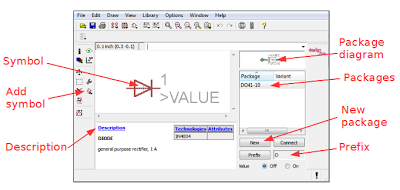
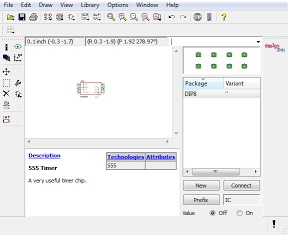
Creating a part is surprisingly tricky - Eagle is one of those software packages with a GUI that looks more intuitive than it is. To create a component, there are three abstractions to deal with: Symbol, Package, and Device. The Symbol is the symbol as it appears in the schematic. It must be tied to a Package, which describes the shape of how the component is physically mounted on a circuit board, in particular the pads for the pins. Finally, the Device holds the complete description of a device, including the symbol and potentially multiple packages. Thus, even if you just want a schematic symbol, you must also deal with the package and device. The following image shows important parts of the Device screen.
Example: Zener diode
For example, suppose you want to create a Zener diode symbol by modifying one of the existing diode symbols.First, find a part in an existing library you want to modify, e.g. use Edit > Add, then Search for something similar. Note the name of the library and the device, e.g. "diode" and "IN4004".
Next, create your custom library by going to the Control Panel and selecting File > New > Library, or open your existing library.
In Control Panel expand the library that has the component you want to copy and find the package you want. Right click and select "Copy to Library".
Next, open the new symbol in your library: Go to Library > Symbol and select the Symbol. Or from the Device screen right click on the crosshair in the middle of the symbol and select Edit Symbol.
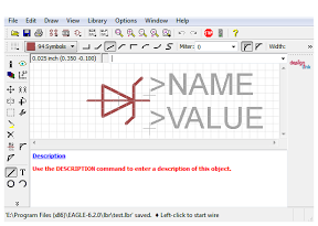
Finally, you can edit the symbol using the standard Eagle editor functions. To make a Zener diode, I needed to change the grid resolution to 0.025, select the angular wire bend, and then use Wire to add the "fins" to make the symbol look like a Zener diode.
Go to File > Save As..., and save the new library.
To use this new library in your schematic, select Library > Use, and add your new library.
Improving the Symbol
The steps above are sufficient to edit and use a new component, but you may want to clean things up a bit.To rename your symbol, go to Library > Rename, and enter a new name for the symbol.
To add a description, click on the Description link and enter a description using HTML. Typically it has <b>the title</b> <p>, and then a description.
To move the >NAME or >VALUE, use move and click on the crosshair at the lower left. You might want to temporarily reduce the grid size to get more control over the position.
Improving the Device
Go to Library > Device, and select the device.To rename the device, use Library > Rename to rename the Device. You can also change the description as above, which is useful for searching.
To change the symbol's prefix (e.g. D1, D2, D3 for diodes), click on Prefix and enter the desired prefix.
You probably just want to have one package, so delete others by right clicking on them on the Device screen and selecting Delete.
To rename the package, go to Library > Package, and select the package. Then use Library > Rename to rename the Package. You can also change the description.
Adding new pins
If you want to add new pins to a symbol, things become more complicated, because you also need to add pads to the package and connect the pins to the pads, even if you don't care about PC boards. I recommend picking a starting symbol with the right number of pins if possible. But if not, use the following steps to add new pins.Add the pins using Draw > Pin. You may need to rotate the pin. Right click the pin and select Properties to change the length or other property. You can enter a pin name or set Visible: Off if you don't want the pin name to show up.
To add pads, go to the Device, right click the Package, and select Edit Package. Add a Pad (anywhere) using the green circle icon.
Next you need to connect the pins and pads. Go to Library > Device and select your device. You will notice in the package pane an exclamation point in a circle. Underneath, click Connect, which will bring up the Connect panel. Select a Pin and a Pad and click Connect, until all pins are connected, and click Ok. Badk at the Device screen, you should now see a checkmark next to the Package. If you don't connect the pad to the pin, you will get "Error: Device ... has unconnected pin (G$1/P$1)!" when you try to add it to the schematic.
Creating an IC (or other component) from scratch
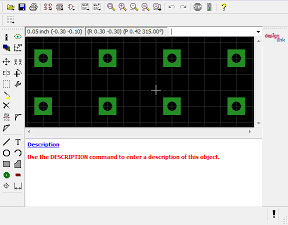
To create an IC, you can modify an existing IC device, a generic package from the ic-package library, or start from scratch. The existing devices are very function-specific and the ic-package symbols are kind of ugly, so you may end up needing to start from scratch. It's not too difficult and only takes a few minutes, but there are more steps than you might expect.First, create a package with the right number of pins. Go to Library > Package, enter your package name (e.g. DIP8) after New, and click Ok. Using the green pad, drop 8 (for example) pads onto the package - the positions don't matter if you're not generating a PCB. Use Properties on each one (right click) to give the pads names 1, 2, etc.
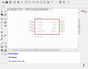
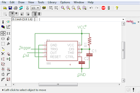
Go to Library > Symbol, enter your symbol name after New (e.g. 555), and click Ok. (For this example, I'll create a 555 timer from scratch even though the library has one.) Put down all the pins for your IC, leaving plenty of room horizontally for the labels, rotating the pins as necessary. Under properties, give each pin the desired name and set length to short. Use four wires to create the outline. Put Text >NAME on the name layer (95) and Text >VALUE on the value layer (96). Add a description if you want.
Go to Library > Device, enter your device name after New (e.g. 555) and click Ok. Click on Add, select your new symbol, and add your symbol to the device. Under the package pane, click New, select your package, and click Ok. Click Connect, and carefully connect all the pins to the right pads, so the pin numbers show up okay. (Tip: do the pins in numerical order.) Click Ok. Add a Prefix and Description if you want.
Save your library with File > Save, and it should be ready to use.
Thanks! This was very helpful and easy to follow.
ReplyDeleteThe tip on "prefix" saved me from pulling out too much more hair. Thanks! Finally all my components are properly named...
ReplyDeleteAny idea why my eagle behaves weirdly, it keeps adding '000' infront of the number of the component wheever I delete and add a component. For example, if I delete C21 and add a new component in its place, it creates C00021 as the new component name. But if I cerate a whole new schematic by copying the schematic from my previous schematic and without copying the board, it works fine.
ReplyDeleteThis comment has been removed by the author.
ReplyDeleteThis was the easiest way for me to learn how to build my own devices.
ReplyDelete